Powerkiss PH2-B1 Wireless charging transmitter User Manual installation guide
Powerkiss Oy Wireless charging transmitter installation guide
Contents
- 1. user manual installation guide
- 2. user manual
- 3. user manual ring
user manual installation guide

This is the
On site
milling guide for Heart
The PowerKiss Heart is a different kind of transmitter for wireless
charging. It does not take up space on your table as it is attached
underneath the tabletop. From there it will charge your devices, without
any cables while the furniture surfaces will remain clean and free just like
you have planned them to be.
For this, the Heart needs to be installed into a specific hole pattern that
can be done either on site or at workshop. This booklet will guide you
how to do the processing on site.
To avoid injury, read all the installation instructions, operating
instructions and safety information in this guide.
Always use powertools and their accessories according to
manufacturer’s instructions and with extreme caution. PowerKiss is
not responsible for third-party products and their quality before or
after the installation.
WARNING
IMPORTANT The operation of PowerKiss Heart is highly dependent on
the accuracy of the performed milling - ensure that you have
understood the specifications of the ready groove before starting,
depicted on pages 9 - 10. If you are unsure about something,
contact your PowerKiss representative.
Before using the jig, it is recommended to practice a few joints with
off-cuts of worktops or other materials to familiarize yourself with
the jig plate.

Specifications
Requirements for the piece of furniture
Feature Requirement
Surface thickness range 22 - 57 mm (0.866 - 2.244 inches)
Material restrictions No metal or magnetic materials directly
above Charging Spot
Minimum Charging Spot distance 200 mm (8 inches)
from the user
Optimal Charging Spot distance 400 x 200 mm (16 x 8 inches), see picture (p. 8)
from the user
6

7How it should look like
How it should look like
8How it should look like
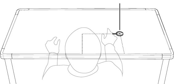
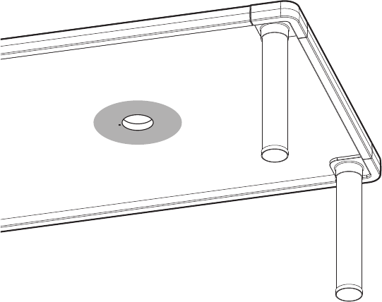
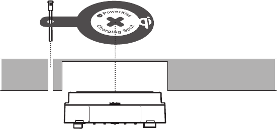
The ready table
The Charging Spot
The hole that is made through the surface is always on the left of the
actual Charging Spot
400 mm
200 mm
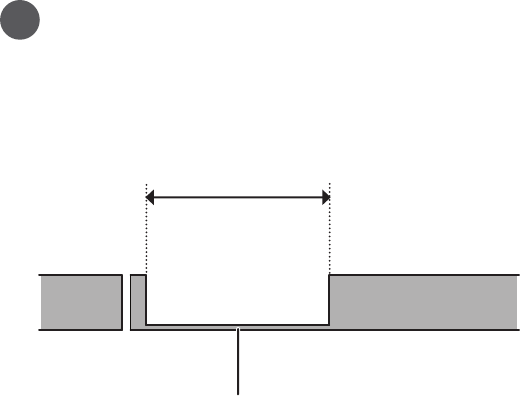
9How it should look like
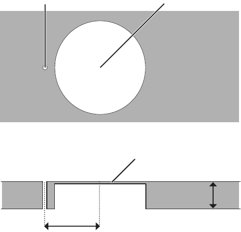
Ø 75 ±1mm (2.95 ±.04 inches) Ø 3.5 mm (9/64 inches)
3 ±0.5mm (1/8 ±.02 inches)
45 ±0.5mm (1 ±.02 inches)
34
/
22 - 57 mm
(0.866 - 2.244 inches)
10 How it should look like
Installation in short
11How it should look like
12 How it should look like

13What you need
What you need
14 What you need
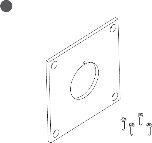
The jig plate and screws
The PowerKiss Router Jig is compatible with all plunge-capable routers
that can be fitted with a 17 mm (0.6693 inches) copy ring
1
15What you need
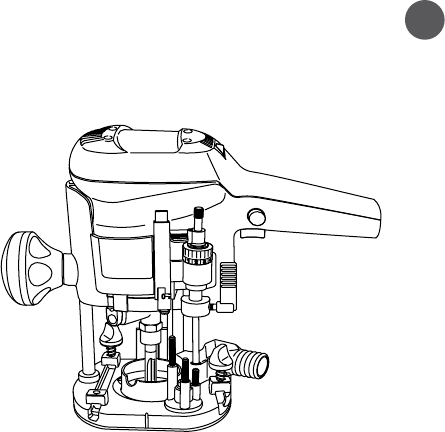
Plunge Router 2
See that the used router bit has sufficient overall length for the target
surface
16 What you need
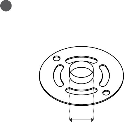
Copy ring for the router
3
Ø17 mm (0.6693 inches)
17What you need
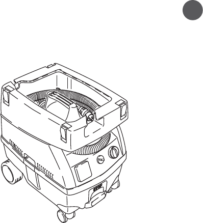
Vacuum cleaner 4
Remember to clean after youself.
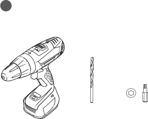
Ø 3.5 mm (9/64 inches) T20 bit
18 What you need
Drill and the correct drill bits
5
19What you need
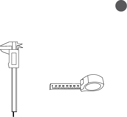
Measuring equipment 6
1
6.00
mm
20 What you need

21How to do it
How to do it
22 How to do it
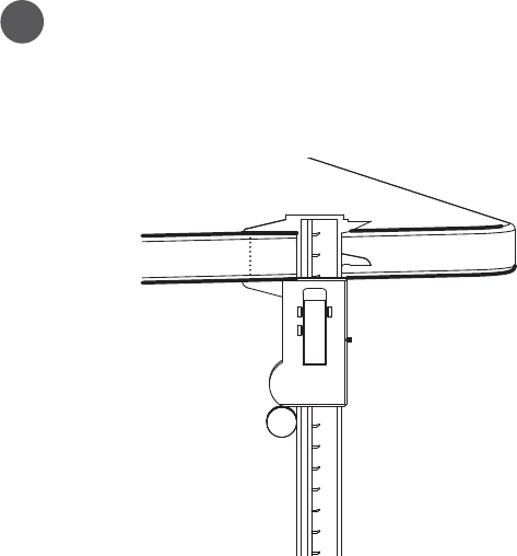
Check the target surface
Measure the table surface thickness with extreme care, using a
caliper. If the thickness is within the range specified, continue.
1
23How to do it
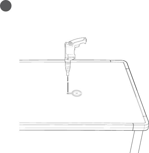
Hole through the table top
Drill a hole of d= 3.5mm (9/64 inches) through the surface of the
furniture at the desired place for the PowerKiss Heart
2
24 How to do it
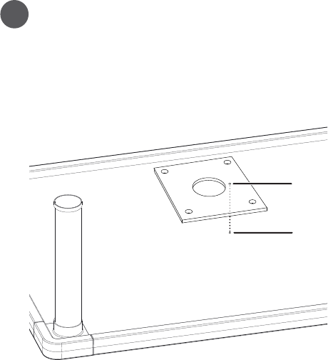
Turn the table and place jig plate
Turn the table around and place the jig plate so that its dia = 5
mm (0.1969 inches) hole is directly above the just drilled 3.5 mm
(9/64 inches) hole
3
Ø 3.5 mm
(9/64 inches)
Ø 5 mm
(0.1969 inches)
25How to do it
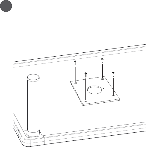
Attach the plate
Attach the jig plate with the provided screws to the surface
4
26 How to do it
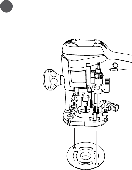
Attach copy ring
Attach the copy ring to the router
5
27How to do it
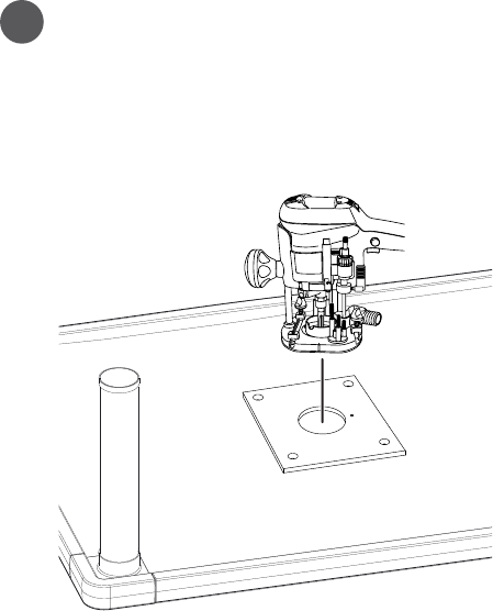
Measure and set the plunge depth
Place the router on the jig plate and measure the needed
plunge depth. The surface thickness at the ready groove must
be 3 ±0.5mm (1/8 ±.02 inches).
Double check the values before starting!
6
28 How to do it
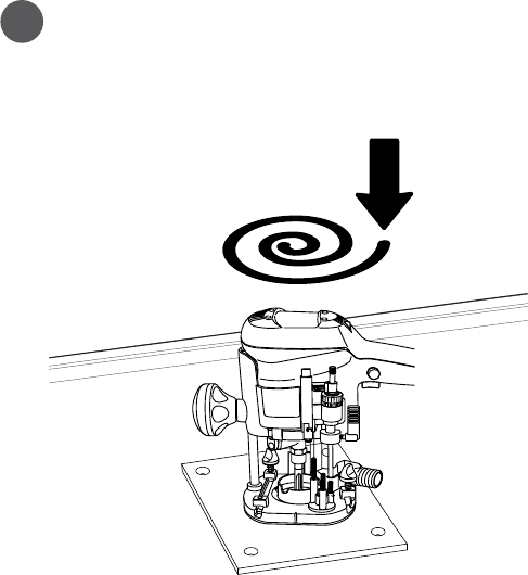
7Do the hole
Turn on the router and plunge it slowly. Guide the router against
the edges of the circle so that the whole fixture of the guide is
processed to the surface
3 ±0.5mm (1/8 ±.02 inches)
75 ±1mm (2.95 ±.04 inches)
29How to do it
Check the result!
8
30 How to do it

31Safety information
Safety information
32 Safety information
Safety information
When using power tools, basic precautions should always be followed.
In particular:
• Before using any power tool, check first for damaged parts and if found,
do not use them before the part or parts have been replaced with new
ones
• Always ensure that the path of the router is kept clear of any obstruction
e.g. clamps
• Always ensure that the cable of the router is clear of the jig and is of
sufficient length
• Do not switch router on with the cutter touching the work piece
• Do not force the router to work fast. This will result in a poor quality cut
and can also damage expensive router bits
• Never remove the router from the jig whilst it is still in motion
• Always allow the router to stop and switch off before removing
• Always keep the router base parallel to the jig, and the router in an
upright position. Failure to do so will cause an unmatched joint
33Safety information
• Don’t over reach; keep proper footing at all times to ensure correct
balance
• Wear safety goggles at all times, everyday glasses are not sufficient for
eye protection as lenses are not impact resistant and could shatter. Use
a face or dust mask if operation is likely to be dusty and ear defenders
during periods of operations
• Don’t wear loose clothing, neckties or jewellery or other items which may
get caught in moving parts. Wear non-slip footwear, cover or tie back long
hair and roll long sleeves above the elbow
• Never exceed 10mm depth cut in one cut
• Be sure to set plunge depth correctly, plunging through the table will
remove the centre plug that guides the jig and create a serious hazard

The images in this guide are examples only.
POWERKISS and the “PowerKiss” Logo are trademarks or
registered trademarks of PowerKiss Ltd.
The “Qi” symbol is a trademark of the Wireless Power Consortium.
© 2013 PowerKiss Ltd. All rights reserved.
Manual no: ZMXXXX, version: 1.0