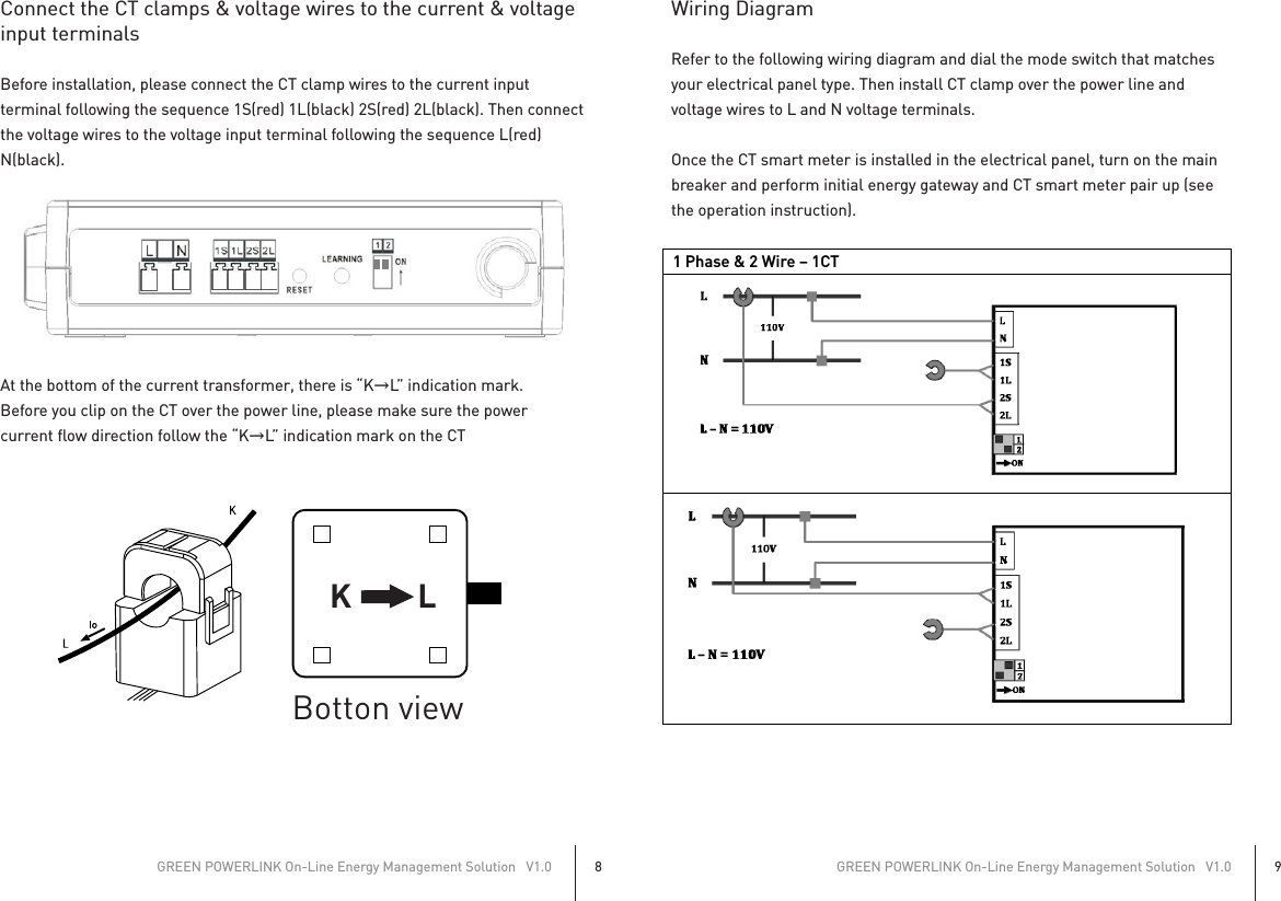
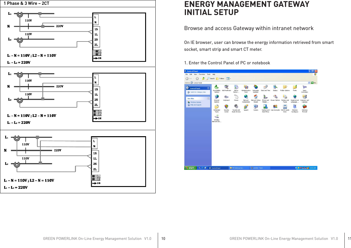
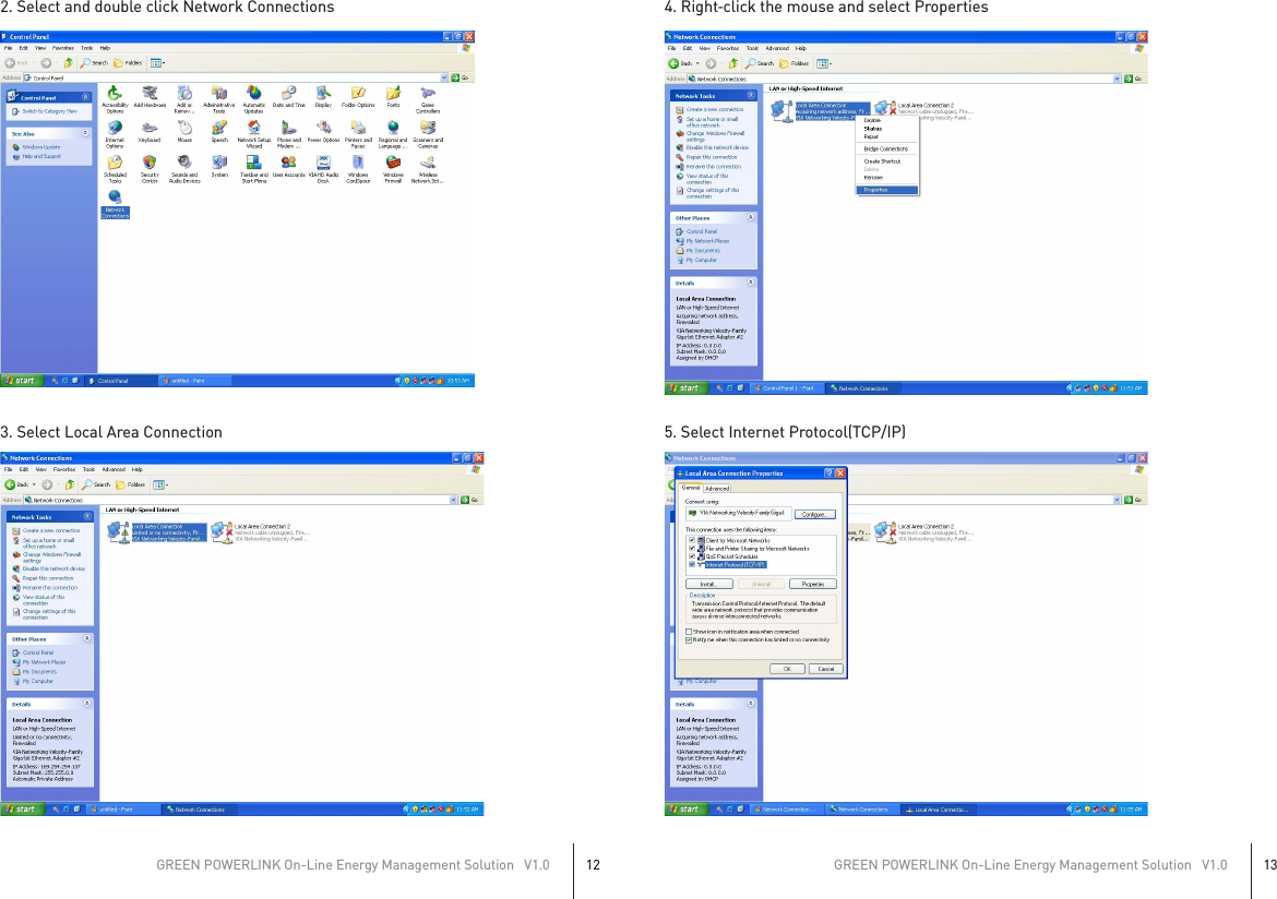
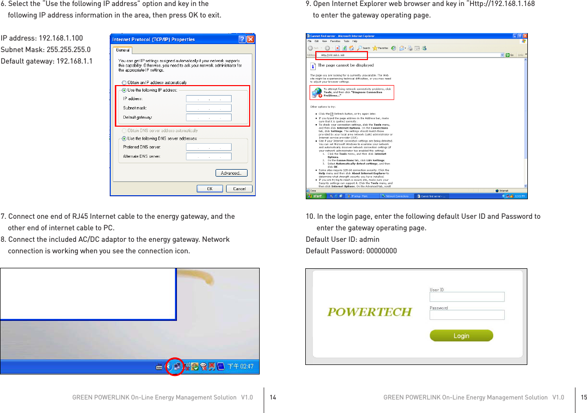
Powertech Co R9P624 Surge Protective Devices User Manual OnLine Energy Management Solution 08202012

Powertech Industrial Co Ltd Surge Protective Devices OnLine Energy Management Solution 08202012

User Manual

GREEN POWERLINKOn-Line Energy Management Solution User Manual© Copyright 2012The information contained herein is subject to change without notice.This document contains proprietary information, which is protected by copyright. No part of this document may be photocopied, reproduced, or translated into another language without the prior written consent.Feb. 2012All Versions
TABLE OF CONTENTSINTRODUCTION...................................................................... 2HARDWARE FEATURES ......................................................... 3INSTALLATION....................................................................... 5Wireless Setup Range.......................................................................... 5Install Smart Socket............................................................................ 5Install Smart Power Strip ................................................................... 6Install CT Smart Meter in the circuit breaker panel............................ 7Prepare the electrical circuit breaker................................................................... 7Connect the CT clamps & voltage wires to the curren& voltage input terminals..................................................................................... 8Wiring Diagram .................................................................................................... 9ENERGY MANAGEMENT GATEWAY INITIAL SETUP.............. 11Browse and access Gateway within intranet network ...................... 11Energy Gateway and Smart Metering Devices pairing instructions... 18Change User ID and Password .........................................................  22Network Setup .................................................................................  22Electricity Cost and CO2 Emission Setup..........................................  23Outgoing Server Setup......................................................................  24Reset the Energy Gateway to Factory Default................................... 24Reset to factory default from energy gateway web server................ 25Browse and access Gateway from internet....................................... 25GREEN POWERLINK On-Line Energy Management Solution   V1.01
INTRODUCTIONThank you for purchasing the GREEN POWERLINK online energy managementsolution, an innovative product which is designed to manage home electricityusage efficiently and reduce home electricity bill.In an effort to reduce your electricity bills, why not first check out whatappliance uses most energy in your home.The GREEN POWERLINK online energy management allows you to take controlof home electricity usage while saving you money in the process.With GREEN POWERLINK, you can see how much electricity you are using andwith greater awareness you’ll become more energy efficient.Fully educated with the critical energy information, you are naturally motivatedto adopt new energy saving habits and reduce harmful carbon emission for ourenvironment.The GREEN POWERLINK is the total solution for green inspiration, energyconservation, and surge protection for your everyday life.GREEN POWERLINK On-Line Energy Management Solution   V1.02GREEN POWERLINK On-Line Energy Management Solution   V1.03HARDWARE FEATURESZigBee Tracking Smart Socket ZigBee Tracking Smart Strip*Surge Protected Outlet*180J Surge Protection*ZigBee Link: 2.4GHz (IEEE 802.15.4)*Transmission Time: 6 seconds*Wireless Range: 100 ft in open area*ZigBee Function: Router*ZigBee Profile: Smart Energy 1.0*ZigBee Cluster: Simple Metering*Green Surge Protected LED Indicator*Manual ON/OFF Button w/ Green LED Indicator*Security: AES 128 bits (Optional)*Meet IEC 62053‐21 class I standard (1~1.5%)*6 Surge Protected Outlets*540J Surge Protection*Red Grounded Fault LED IndicatorR9P136A600 R9P624NI00
ZigBee Tracking Smart Socket ZigBee Tracking Smart Strip*Transmission Time: 6 seconds*ZigBee Function: Router*ZigBee Cluster: Simple Metering*Installation type: 1‐phase & 3‐wire*CT Meter Input Voltage:100~240V*CT Meter Input Current: 60A*CT Meter Frequency: 50/60Hz*CT Meter Accuracy: <1% at PF=1*Power Supply: Power acquired    from electrical meter*ZigBee Link: 2.4GHz (IEEE 802.15.4)*Wireless Range: 100 ft in open area*ZigBee Profile: Smart Energy 1.0*Security: AES 128 bits (Optional)*Link up to 9 PowerLink energy    tracking devices*ZigBee Function: Coordinator*Proprietary remote outlet on/off    control*Remote web browsing management     & power on/off control*Remote real time Cost, KWH, CO2    usage information display*RJ45 Ethernet Port Connection*Power Supply: AC/DC adaptor    (included)GREEN POWERLINK On-Line Energy Management Solution   V1.04GREEN POWERLINK On-Line Energy Management Solution   V1.05INSTALLATIONWireless Setup RangeThe energy gateway and smart socket/strip/CT meter communicate with wireless technology. To ensure the communication with no interruption, please locate and setup energy gateway, smart socket/strip/CT meter within 100 Ft of range.Install Smart SocketThe single outlet smart socket allows the user to track electricity consumption of individual home appliance and protect it against surge and voltage spikes.1. Plug in the smart socket to a powered AC outlet.2. Plug in the appliance into the smart socket outlet.3. The outlet power can be manually turned ON/OFF by pressing the “Manual    ON/OFF” button on the smart socket. You may also control the outlet power    remotely by using the energy monitor (see the operation instruction).4. Perform initial energy monitor and smart socket pair up (see the operation    instruction).PROTECTED LED LIGHTThis LED light illuminatesto indicate that the surgeprotection is active andprotecting equipmentsfrom power surges.Manual ON/OFF”buttonM9PC020000 M9PG040000
Install Smart Power StripThe smart power strip allows the user to track electricity consumption of grouphome appliances in the same area and protect it against surge and voltage spikes.1. Plug in the smart power strip to a powered AC outlet.2. Plug in the appliances into the smart power strip outlets.3. The Energy Saver outlets on the power strip can be manually turned ON/OFF    by pressing the “Manual ON/OFF” button on the power strip. You may also    control the energy saver outlets remotely by using the energy monitor (see    the operation instruction).4. Perform initial energy monitor and smart power strip pair up (see the    operation instruction).GREEN POWERLINK On-Line Energy Management Solution   V1.06GREEN POWERLINK On-Line Energy Management Solution   V1.07Install CT Smart Meter in the circuit breaker panelThe CT smart meter allows the user to measure entire electricity powerconsumption from electrical panel.                CautionYour safety is very important to us. Please read these cautions regarding the installation of your CT Smart Meter.*Electrical panel contains live electrical wires and components even when the main circuit breaker has been switched off. Do not attempt any installation unless you are familiar where these electrified areas are.*Any work on or near electrical panel could induce danger or fatal electrical shock. It is highly recommended that all work should be done only by qualified electricians or certified electrical specialist.Prepare the electrical circuit breakerWARNING:*Before you start, you must turn off all power in the electrical circuit breaker by turning off the main breaker or main switch.*Some wires and components could still be live even when the main breaker or switch is turned off. Please indentify these wires and components before installation and pay attention to these areas at all time.1. Turn off all power by turning off the main breaker or main switch.2. Remove the cover of electricity circuit breaker panel.Manual ON/OFF”buttonPROTECTED LED LIGHTThis LED light illuminatesto indicate that the surgeprotection is active andprotecting equipmentsfrom power surges.GROUNDED LED LIGHTThis LED light illuminates to indicate that the surgeprotector is plugged into aproperly grounded outlet.ALWAYS ON OUTLETSare also available fordevices which are alwayskept on and needcontinuous power.!
Connect the CT clamps & voltage wires to the current & voltageinput terminalsBefore installation, please connect the CT clamp wires to the current inputterminal following the sequence 1S(red) 1L(black) 2S(red) 2L(black). Then connectthe voltage wires to the voltage input terminal following the sequence L(red)N(black).At the bottom of the current transformer, there is “K→L” indication mark.Before you clip on the CT over the power line, please make sure the powercurrent flow direction follow the “K→L” indication mark on the CTGREEN POWERLINK On-Line Energy Management Solution   V1.08GREEN POWERLINK On-Line Energy Management Solution   V1.09Wiring DiagramRefer to the following wiring diagram and dial the mode switch that matches your electrical panel type. Then install CT clamp over the power line and voltage wires to L and N voltage terminals.Once the CT smart meter is installed in the electrical panel, turn on the mainbreaker and perform initial energy gateway and CT smart meter pair up (see the operation instruction).K LBotton view       1 Phase & 2 Wire – 1CT
GREEN POWERLINK On-Line Energy Management Solution   V1.010GREEN POWERLINK On-Line Energy Management Solution   V1.011ENERGY MANAGEMENT GATEWAYINITIAL SETUPBrowse and access Gateway within intranet networkOn IE browser, user can browse the energy information retrieved from smartsocket, smart strip and smart CT meter.1. Enter the Control Panel of PC or notebook              1 Phase & 3 Wire – 2CT
2. Select and double click Network Connections3. Select Local Area Connection4. Right‐click the mouse and select Properties5. Select Internet Protocol(TCP/IP)GREEN POWERLINK On-Line Energy Management Solution   V1.012GREEN POWERLINK On-Line Energy Management Solution   V1.013
6. Select the “Use the following IP address” option and key in the         following IP address information in the area, then press OK to exit.IP address: 192.168.1.100Subnet Mask: 255.255.255.0Default gateway: 192.168.1.17. Connect one end of RJ45 Internet cable to the energy gateway, and the             other end of internet cable to PC.8. Connect the included AC/DC adaptor to the energy gateway. Network    connection is working when you see the connection icon.9. Open Internet Explorer web browser and key in “Http://192.168.1.168     to enter the gateway operating page.10. In the login page, enter the following default User ID and Password to       enter the gateway operating page.Default User ID: adminDefault Password: 00000000GREEN POWERLINK On-Line Energy Management Solution   V1.014GREEN POWERLINK On-Line Energy Management Solution   V1.015
11. To set up Internet Explorer to work with the energy gateway, click on toolsand select internet options12. Select Settings in internet options page to setup temporary internet filesoption.13. To check for newer version of stored pages, check on “Every visit to the page”option then press OK to exit.GREEN POWERLINK On-Line Energy Management Solution   V1.016GREEN POWERLINK On-Line Energy Management Solution   V1.017
Energy Gateway and Smart MeteringDevices pairing instructionsThe learning function allows you to expand smart sockets/strips/CT meters lateron. You may purchase more compatible smart metering devices and pair up to 9smart metering devices to the energy monitor.1. We suggest using a notebook when pairing up energy gateway and smart    devices. Please bring the notebook and energy gateway close to smart    sockets/strips/CT meter for smart devices pairing.2. Click on “Channel” in the energy gateway operating page.4. In the channel page, from CH1 to 9, select which channel you would like to add    the smart device to the energy gateway. Then click on connect key to pair up    the smart device with the energy gateway.GREEN POWERLINK On-Line Energy Management Solution   V1.018GREEN POWERLINK On-Line Energy Management Solution   V1.019
5. In Channel Name Settings, you can set a name for the channel and press Apply    to save it. For smart power strip user, you can set a name for individual outlet.    This will help you to recognize what are the devices connected to smart    power strip.6. After the smart device and energy gateway finished pairing up, the LED    indicator on the smart devices will stop flashing. If the smart device has    successfully paired up with the energy gateway, it will display “Connected” in    the column.7. In “Device State” page, you can see the power consumption information of the    smart devices. You can also control the smart socket and strip by click the ON    & OFF icon.8. Repeat step2 to step5 to add more smart devices to different channel on theenergy monitor.GREEN POWERLINK On-Line Energy Management Solution   V1.020GREEN POWERLINK On-Line Energy Management Solution   V1.021
Change User ID and Password1. Click on “User” in the energy gateway operating page.2. Change the User ID to your preference.3. Enter your new password and confirm the new password.4. Click on “Apply” to perform User ID and Password change.Network SetupThe network setting allows the user to setup network as static IP or DHCP mode.1. Click on “Network” in the energy gateway operating page.2. According to your network environment, select Static IP or DHCP as your option.3. Enter the network IP information.4. Click on “Apply” to perform network setup.Electricity Cost and CO2 Emission SetupIn the event your local utility uses a tariff calculation other than flat electricityrate, please key in the average rate that most nearly resembles your utility’stariff schedule.Carbon dioxide is emitted in the process of producing electricity by burning coal& fossil fuel. This is usually referred to CO2 footprint or carbon emission, whichin turn has contributed global warming and caused abnormal weather.The average carbon emission rate is 0.49Kg (1.08 lbs) of carbon emission forevery 1 KWH of electricity produced. This can be changed depending upon yourlocal electric utility. Please contact your local utility for carbon emission rate.1. Click on “Cost & CO2” in the energy gateway operating page.2. According to your local utility electricity and carbon emission rate, enter theinformation in the columns.3. Click on “Apply” to perform Cost & CO2 setup.GREEN POWERLINK On-Line Energy Management Solution   V1.022GREEN POWERLINK On-Line Energy Management Solution   V1.023
Outgoing Server Setup The energy gateway can collect energy database and transmit onto designatedserver for energy management service.1. Click on “Server” in the energy gateway operating page.2. Enter the designated server information and transmission time interval.3. Click on “Apply” to perform confirm server setting setup.Reset the Energy Gateway to Factory DefaultThere are two ways to reset the energy gateway to factory default, please followthe instruction below to reset the gateway to its factory default setting.Warning: By performing resetting the gateway to factory default, all saved data, network settings & channel settings will be restored to factory default.Reset to factory default from the energy gateway1. Locate the reset point on the gateway.2. Push a stylus or pen into the reset point for 5 seconds.3. The gateway will be hard reset to factory default setting. Please perform all thenecessary setup and channel setting.Reset to factory default from energy gateway web server1. Click on the “Defaults” in the energy gateway operation page.2. Clink on the “Apply” to reset to factory default.3. The gateway will be hard reset to factory default setting. Please perform all the    necessary setup and channel setting.Browse and access Gateway from internetAnywhere and anytime, user can browse energy consumptionof the connected appliances and control poweron/off from internet.GREEN POWERLINK On-Line Energy Management Solution   V1.024GREEN POWERLINK On-Line Energy Management Solution   V1.025Smart SocketGatewayRouter w/NAT2-Way RFInternetServiceProviderInternetAccess the gatewayfrom internet
In order for user to browse and access Gateway from internet, the followingrequirements are needed*Fix public IP address provided by internet service provider (ISP)*Router with Network Address Translation (NAT) serviceUser will first be required to obtain a fix IP address provided by internet serviceprovider, then enable and setup the network address translation (NAT) service inthe router. Please refer to the Network Address Translation (NAT) instruction inyour router manual.Once the NAT service is enable and setup, user can access the gateway anywherefrom internet by opening IE web browser and key in the fix public IP addressprovided by your internet service provider. The NAT service of the router willredirect your access request to the corresponding gateway.A typical example of Network Address Translation (NAT) setup is provided in thefollowing example instruction.1. Login the router2. Select Advanced setup and choose the languag3. Enter “NAT” setup page.GREEN POWERLINK On-Line Energy Management Solution   V1.026GREEN POWERLINK On-Line Energy Management Solution   V1.027
4. Enable Network Address Translation (NAT) service.5. Select “Application”6. In the application page, key in the Gateway IP address information as following    example.*Select “HTTP” as Service Name.*Select Port 80 as your Gateway port selection*Key in the IP address of the gateway*Press apply to finish NAT setup7. Once NAT service of the router is setup, user can access the gateway    anywhere from internet by opening IE web browser and key in the fix public    IP address provided by your internet service providerGREEN POWERLINK On-Line Energy Management Solution   V1.028GREEN POWERLINK On-Line Energy Management Solution   V1.029
8. The NAT service of the router will redirect your access request to thecorresponding Gateway.                   CAUTION:To assure continued FCC compliance:Any changes or modifications not expressly approved by the grantee of this device could void the user's authority to operate the equipment.GREEN POWERLINK On-Line Energy Management Solution   V1.030GREEN POWERLINK On-Line Energy Management Solution   V1.031 !

Navigation menu