Powertech Co R9P624 Surge Protective Devices User Manual OnLine Energy Management Solution 08202012
Powertech Industrial Co Ltd Surge Protective Devices OnLine Energy Management Solution 08202012
User Manual
GREEN POWERLINK
On-Line Energy Management Solution
User Manual
© Copyright 2012
The information contained herein is subject to change without notice.
This document contains proprietary information, which is protected by copyright.
No part of this document may be photocopied, reproduced,
or translated into another language without the prior written consent.
Feb. 2012
All Versions

TABLE OF CONTENTS
INTRODUCTION...................................................................... 2
HARDWARE FEATURES ......................................................... 3
INSTALLATION....................................................................... 5
Wireless Setup Range.......................................................................... 5
Install Smart Socket............................................................................ 5
Install Smart Power Strip ................................................................... 6
Install CT Smart Meter in the circuit breaker panel............................ 7
Prepare the electrical circuit breaker................................................................... 7
Connect the CT clamps & voltage wires to the curren
& voltage input terminals..................................................................................... 8
Wiring Diagram .................................................................................................... 9
ENERGY MANAGEMENT GATEWAY INITIAL SETUP.............. 11
Browse and access Gateway within intranet network ...................... 11
Energy Gateway and Smart Metering Devices pairing instructions... 18
Change User ID and Password ......................................................... 22
Network Setup ................................................................................. 22
Electricity Cost and CO2 Emission Setup.......................................... 23
Outgoing Server Setup...................................................................... 24
Reset the Energy Gateway to Factory Default................................... 24
Reset to factory default from energy gateway web server................ 25
Browse and access Gateway from internet....................................... 25
GREEN POWERLINK On-Line Energy Management Solution V1.0
1
INTRODUCTION
Thank you for purchasing the GREEN POWERLINK online energy management
solution, an innovative product which is designed to manage home electricity
usage efficiently and reduce home electricity bill.
In an effort to reduce your electricity bills, why not first check out what
appliance uses most energy in your home.
The GREEN POWERLINK online energy management allows you to take control
of home electricity usage while saving you money in the process.
With GREEN POWERLINK, you can see how much electricity you are using and
with greater awareness you’ll become more energy efficient.
Fully educated with the critical energy information, you are naturally motivated
to adopt new energy saving habits and reduce harmful carbon emission for our
environment.
The GREEN POWERLINK is the total solution for green inspiration, energy
conservation, and surge protection for your everyday life.
GREEN POWERLINK On-Line Energy Management Solution V1.0
2
GREEN POWERLINK On-Line Energy Management Solution V1.0
3
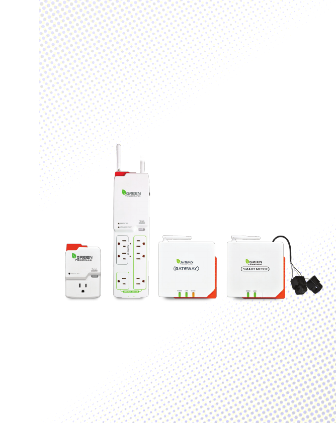
HARDWARE FEATURES
ZigBee Tracking Smart Socket ZigBee Tracking Smart Strip
*Surge Protected Outlet
*180J Surge Protection
*ZigBee Link: 2.4GHz (IEEE 802.15.4)
*Transmission Time: 6 seconds
*Wireless Range: 100 ft in open area
*ZigBee Function: Router
*ZigBee Profile: Smart Energy 1.0
*ZigBee Cluster: Simple Metering
*Green Surge Protected LED Indicator
*Manual ON/OFF Button w/ Green LED Indicator
*Security: AES 128 bits (Optional)
*Meet IEC 62053‐21 class I standard (1~1.5%)
*6 Surge Protected Outlets
*540J Surge Protection
*Red Grounded Fault LED Indicator
R9P136A600 R9P624NI00
ZigBee Tracking Smart Socket ZigBee Tracking Smart Strip
*Transmission Time: 6 seconds
*ZigBee Function: Router
*ZigBee Cluster: Simple Metering
*Installation type: 1‐phase & 3‐wire
*CT Meter Input Voltage:100~240V
*CT Meter Input Current: 60A
*CT Meter Frequency: 50/60Hz
*CT Meter Accuracy: <1% at PF=1
*Power Supply: Power acquired
from electrical meter
*ZigBee Link: 2.4GHz (IEEE 802.15.4)
*Wireless Range: 100 ft in open area
*ZigBee Profile: Smart Energy 1.0
*Security: AES 128 bits (Optional)
*Link up to 9 PowerLink energy
tracking devices
*ZigBee Function: Coordinator
*Proprietary remote outlet on/off
control
*Remote web browsing management
& power on/off control
*Remote real time Cost, KWH, CO2
usage information display
*RJ45 Ethernet Port Connection
*Power Supply: AC/DC adaptor
(included)
GREEN POWERLINK On-Line Energy Management Solution V1.0
4
GREEN POWERLINK On-Line Energy Management Solution V1.0
5
INSTALLATION
Wireless Setup Range
The energy gateway and smart socket/strip/CT meter communicate with
wireless technology. To ensure the communication with no interruption,
please locate and setup energy gateway, smart socket/strip/CT meter within
100 Ft of range.
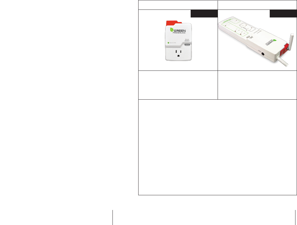
Install Smart Socket
The single outlet smart socket allows the user to track electricity consumption
of individual home appliance and protect it against surge and voltage spikes.
1. Plug in the smart socket to a powered AC outlet.
2. Plug in the appliance into the smart socket outlet.
3. The outlet power can be manually turned ON/OFF by pressing the “Manual
ON/OFF” button on the smart socket. You may also control the outlet power
remotely by using the energy monitor (see the operation instruction).
4. Perform initial energy monitor and smart socket pair up (see the operation
instruction).
PROTECTED LED LIGHT
This LED light illuminates
to indicate that the surge
protection is active and
protecting equipments
from power surges.
Manual ON/OFF”
button
M9PC020000 M9PG040000
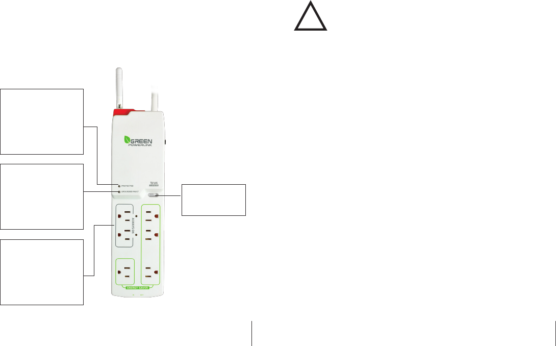
Install Smart Power Strip
The smart power strip allows the user to track electricity consumption of group
home appliances in the same area and protect it against surge and voltage spikes.
1. Plug in the smart power strip to a powered AC outlet.
2. Plug in the appliances into the smart power strip outlets.
3. The Energy Saver outlets on the power strip can be manually turned ON/OFF
by pressing the “Manual ON/OFF” button on the power strip. You may also
control the energy saver outlets remotely by using the energy monitor (see
the operation instruction).
4. Perform initial energy monitor and smart power strip pair up (see the
operation instruction).
GREEN POWERLINK On-Line Energy Management Solution V1.0
6
GREEN POWERLINK On-Line Energy Management Solution V1.0
7
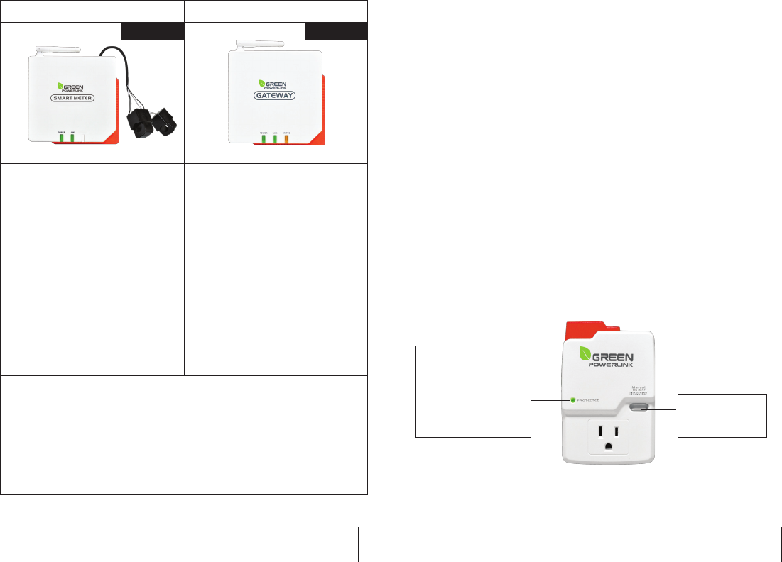
Install CT Smart Meter in the circuit breaker panel
The CT smart meter allows the user to measure entire electricity
powerconsumption from electrical panel.
Caution
Your safety is very important to us. Please read these cautions
regarding the installation of your CT Smart Meter.
*Electrical panel contains live electrical wires and components even
when the main circuit breaker has been switched off. Do not attempt
any installation unless you are familiar where these electrified areas
are.
*Any work on or near electrical panel could induce danger or fatal
electrical shock. It is highly recommended that all work should be
done only by qualified electricians or certified electrical specialist.
Prepare the electrical circuit breaker
WARNING:
*Before you start, you must turn off all power in the electrical circuit
breaker by turning off the main breaker or main switch.
*Some wires and components could still be live even when the main
breaker or switch is turned off. Please indentify these wires and
components before installation and pay attention to these areas at all
time.
1. Turn off all power by turning off the main breaker or main switch.
2. Remove the cover of electricity circuit breaker panel.
Manual ON/OFF”
button
PROTECTED LED LIGHT
This LED light illuminates
to indicate that the surge
protection is active and
protecting equipments
from power surges.
GROUNDED LED LIGHT
This LED light illuminates
to indicate that the surge
protector is plugged into a
properly grounded outlet.
ALWAYS ON OUTLETS
are also available for
devices which are always
kept on and need
continuous power.
!
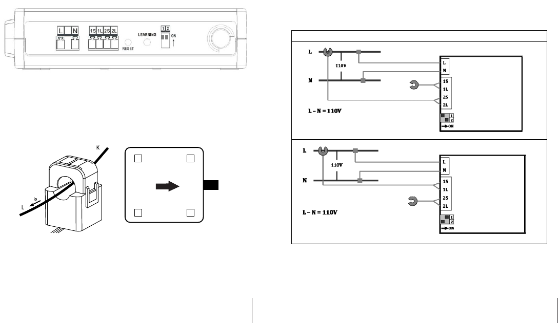
Connect the CT clamps & voltage wires to the current & voltage
input terminals
Before installation, please connect the CT clamp wires to the current input
terminal following the sequence 1S(red) 1L(black) 2S(red) 2L(black). Then connect
the voltage wires to the voltage input terminal following the sequence L(red)
N(black).
At the bottom of the current transformer, there is “K→L” indication mark.
Before you clip on the CT over the power line, please make sure the power
current flow direction follow the “K→L” indication mark on the CT
GREEN POWERLINK On-Line Energy Management Solution V1.0
8
GREEN POWERLINK On-Line Energy Management Solution V1.0
9
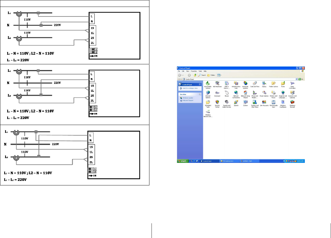
Wiring Diagram
Refer to the following wiring diagram and dial the mode switch that matches
your electrical panel type. Then install CT clamp over the power line and
voltage wires to L and N voltage terminals.
Once the CT smart meter is installed in the electrical panel, turn on the main
breaker and perform initial energy gateway and CT smart meter pair up (see
the operation instruction).
K L
Botton view
1 Phase & 2 Wire – 1CT
GREEN POWERLINK On-Line Energy Management Solution V1.0
10
GREEN POWERLINK On-Line Energy Management Solution V1.0
11
ENERGY MANAGEMENT GATEWAY
INITIAL SETUP
Browse and access Gateway within intranet network
On IE browser, user can browse the energy information retrieved from smart
socket, smart strip and smart CT meter.
1. Enter the Control Panel of PC or notebook
1 Phase & 3 Wire – 2CT
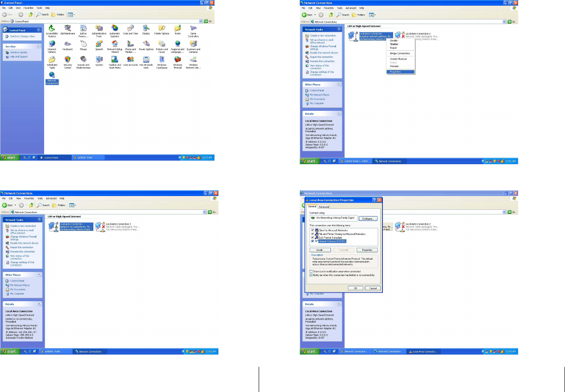
2. Select and double click Network Connections
3. Select Local Area Connection
4. Right‐click the mouse and select Properties
5. Select Internet Protocol(TCP/IP)
GREEN POWERLINK On-Line Energy Management Solution V1.0
12
GREEN POWERLINK On-Line Energy Management Solution V1.0
13
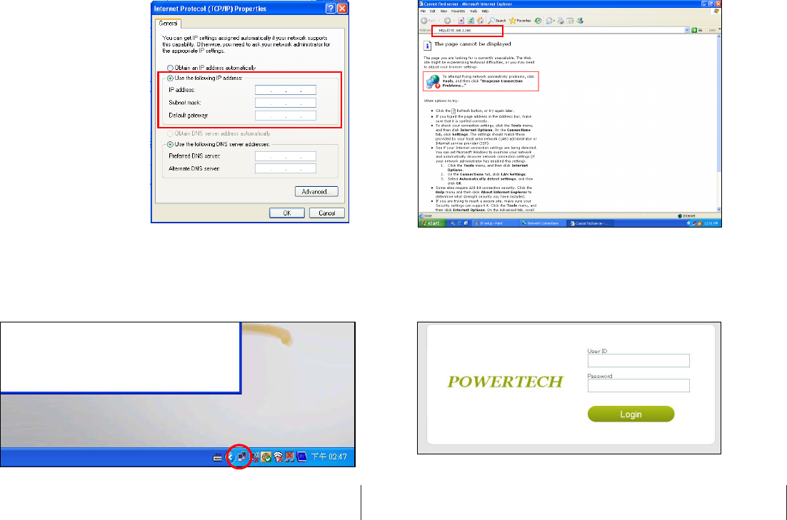
6. Select the “Use the following IP address” option and key in the
following IP address information in the area, then press OK to exit.
IP address: 192.168.1.100
Subnet Mask: 255.255.255.0
Default gateway: 192.168.1.1
7. Connect one end of RJ45 Internet cable to the energy gateway, and the
other end of internet cable to PC.
8. Connect the included AC/DC adaptor to the energy gateway. Network
connection is working when you see the connection icon.
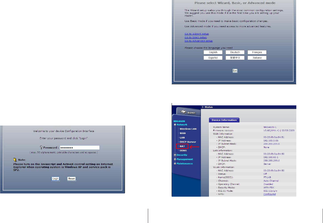
9. Open Internet Explorer web browser and key in “Http://192.168.1.168
to enter the gateway operating page.
10. In the login page, enter the following default User ID and Password to
enter the gateway operating page.
Default User ID: admin
Default Password: 00000000
GREEN POWERLINK On-Line Energy Management Solution V1.0
14
GREEN POWERLINK On-Line Energy Management Solution V1.0
15
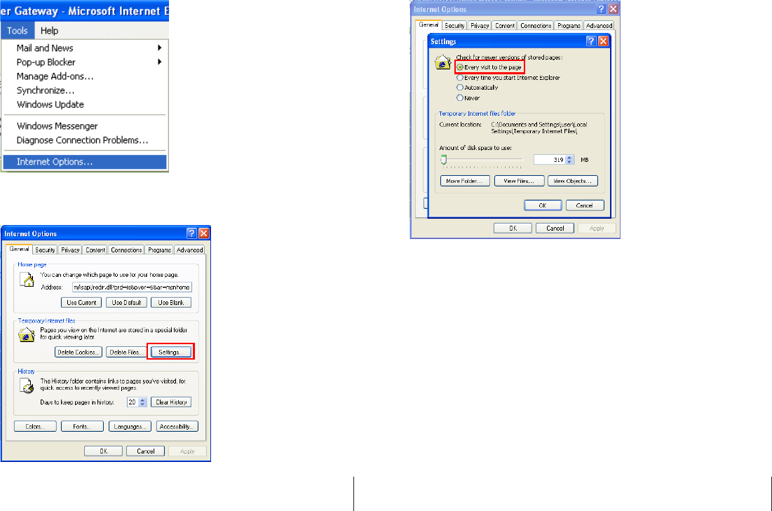
11. To set up Internet Explorer to work with the energy gateway, click on tools
and select internet options
12. Select Settings in internet options page to setup temporary internet files
option.
13. To check for newer version of stored pages, check on “Every visit to the page”
option then press OK to exit.
GREEN POWERLINK On-Line Energy Management Solution V1.0
16
GREEN POWERLINK On-Line Energy Management Solution V1.0
17
Energy Gateway and Smart Metering
Devices pairing instructions
The learning function allows you to expand smart sockets/strips/CT meters later
on. You may purchase more compatible smart metering devices and pair up to 9
smart metering devices to the energy monitor.
1. We suggest using a notebook when pairing up energy gateway and smart
devices. Please bring the notebook and energy gateway close to smart
sockets/strips/CT meter for smart devices pairing.
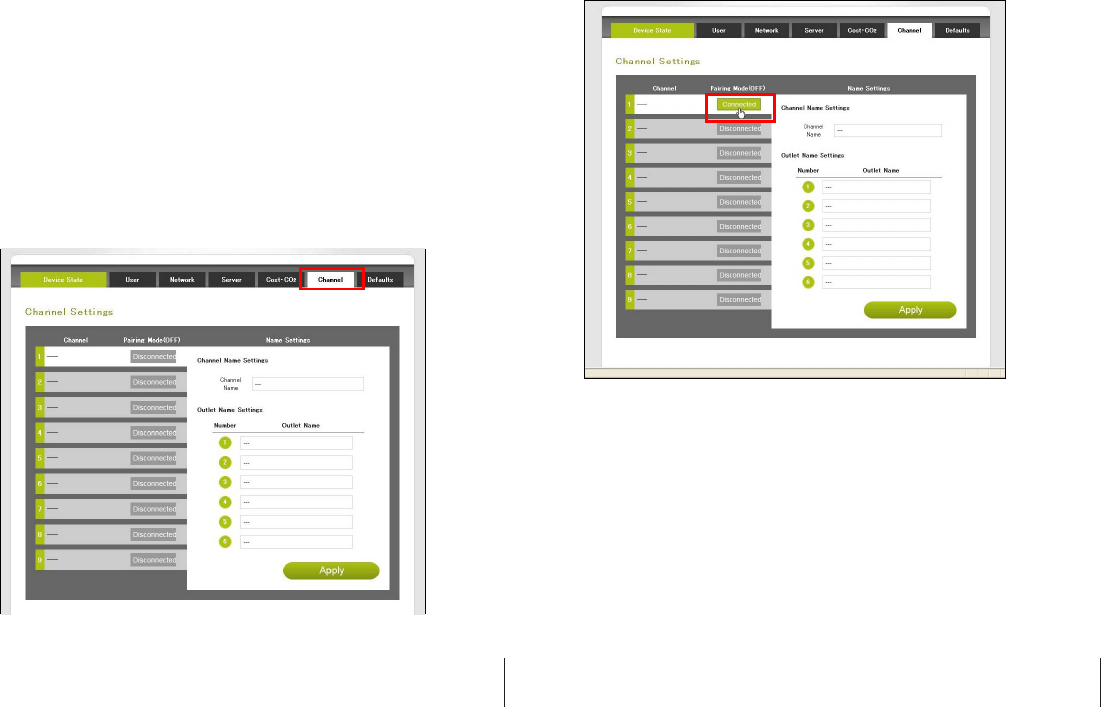
2. Click on “Channel” in the energy gateway operating page.
4. In the channel page, from CH1 to 9, select which channel you would like to add
the smart device to the energy gateway. Then click on connect key to pair up
the smart device with the energy gateway.
GREEN POWERLINK On-Line Energy Management Solution V1.0
18
GREEN POWERLINK On-Line Energy Management Solution V1.0
19
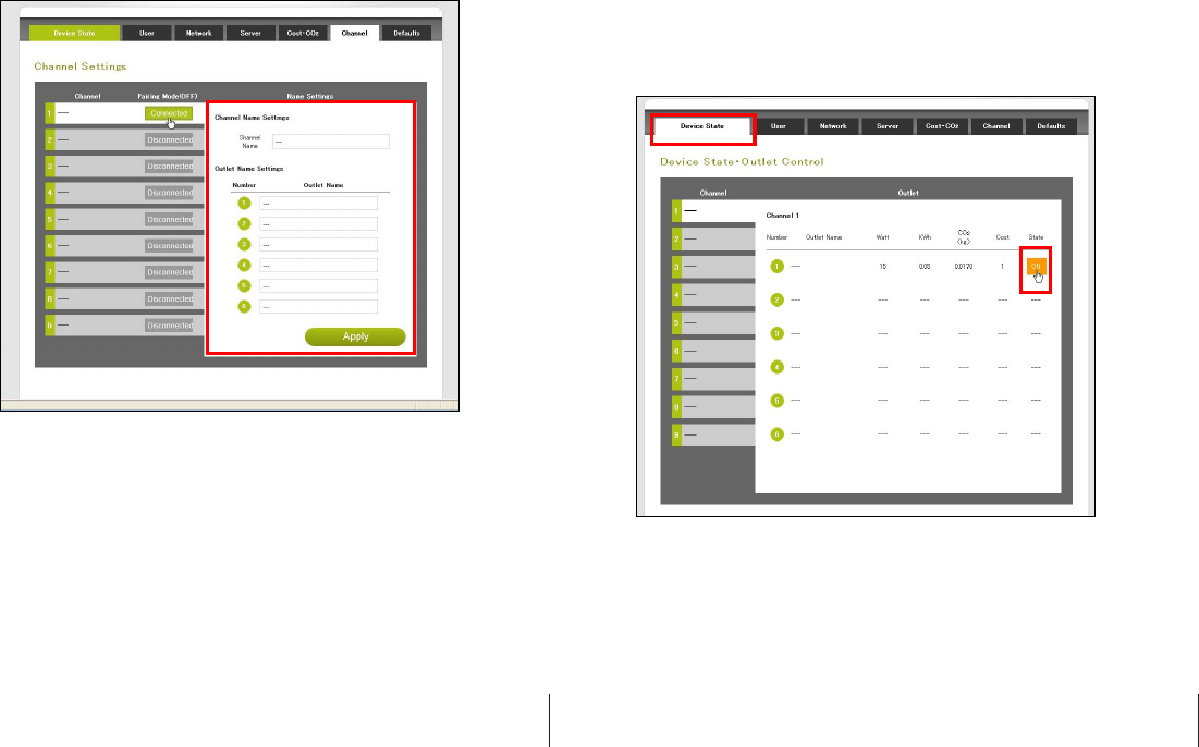
5. In Channel Name Settings, you can set a name for the channel and press Apply
to save it. For smart power strip user, you can set a name for individual outlet.
This will help you to recognize what are the devices connected to smart
power strip.
6. After the smart device and energy gateway finished pairing up, the LED
indicator on the smart devices will stop flashing. If the smart device has
successfully paired up with the energy gateway, it will display “Connected” in
the column.
7. In “Device State” page, you can see the power consumption information of the
smart devices. You can also control the smart socket and strip by click the ON
& OFF icon.
8. Repeat step2 to step5 to add more smart devices to different channel on the
energy monitor.
GREEN POWERLINK On-Line Energy Management Solution V1.0
20
GREEN POWERLINK On-Line Energy Management Solution V1.0
21
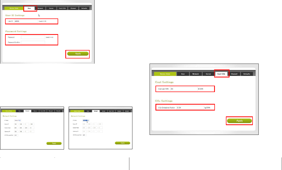
Change User ID and Password
1. Click on “User” in the energy gateway operating page.
2. Change the User ID to your preference.
3. Enter your new password and confirm the new password.
4. Click on “Apply” to perform User ID and Password change.
Network Setup
The network setting allows the user to setup network as static IP or DHCP mode.
1. Click on “Network” in the energy gateway operating page.
2. According to your network environment, select Static IP or DHCP as your option.
3. Enter the network IP information.
4. Click on “Apply” to perform network setup.
Electricity Cost and CO2 Emission Setup
In the event your local utility uses a tariff calculation other than flat electricity
rate, please key in the average rate that most nearly resembles your utility’s
tariff schedule.
Carbon dioxide is emitted in the process of producing electricity by burning coal
& fossil fuel. This is usually referred to CO2 footprint or carbon emission, which
in turn has contributed global warming and caused abnormal weather.
The average carbon emission rate is 0.49Kg (1.08 lbs) of carbon emission for
every 1 KWH of electricity produced. This can be changed depending upon your
local electric utility. Please contact your local utility for carbon emission rate.
1. Click on “Cost & CO2” in the energy gateway operating page.
2. According to your local utility electricity and carbon emission rate, enter the
information in the columns.
3. Click on “Apply” to perform Cost & CO2 setup.
GREEN POWERLINK On-Line Energy Management Solution V1.0
22
GREEN POWERLINK On-Line Energy Management Solution V1.0
23
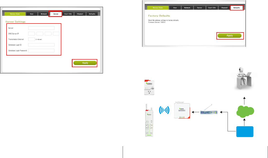
Outgoing Server Setup
The energy gateway can collect energy database and transmit onto designated
server for energy management service.
1. Click on “Server” in the energy gateway operating page.
2. Enter the designated server information and transmission time interval.
3. Click on “Apply” to perform confirm server setting setup.
Reset the Energy Gateway to Factory Default
There are two ways to reset the energy gateway to factory default, please follow
the instruction below to reset the gateway to its factory default setting.
Warning: By performing resetting the gateway to factory default, all saved data,
network settings & channel settings will be restored to factory default.
Reset to factory default from the energy gateway
1. Locate the reset point on the gateway.
2. Push a stylus or pen into the reset point for 5 seconds.
3. The gateway will be hard reset to factory default setting. Please perform all the
necessary setup and channel setting.
Reset to factory default from energy gateway web server
1. Click on the “Defaults” in the energy gateway operation page.
2. Clink on the “Apply” to reset to factory default.
3. The gateway will be hard reset to factory default setting. Please perform all the
necessary setup and channel setting.
Browse and access Gateway from internet
Anywhere and anytime, user can browse energy consumption
of the connected appliances and control power
on/off from internet.
GREEN POWERLINK On-Line Energy Management Solution V1.0
24
GREEN POWERLINK On-Line Energy Management Solution V1.0
25
Smart Socket
Gateway
Router w/NAT
2-Way RF
Internet
Service
Provider
Internet
Access the gateway
from internet
In order for user to browse and access Gateway from internet, the following
requirements are needed
*Fix public IP address provided by internet service provider (ISP)
*Router with Network Address Translation (NAT) service
User will first be required to obtain a fix IP address provided by internet service
provider, then enable and setup the network address translation (NAT) service in
the router. Please refer to the Network Address Translation (NAT) instruction in
your router manual.
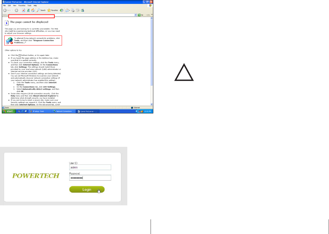
Once the NAT service is enable and setup, user can access the gateway anywhere
from internet by opening IE web browser and key in the fix public IP address
provided by your internet service provider. The NAT service of the router will
redirect your access request to the corresponding gateway.
A typical example of Network Address Translation (NAT) setup is provided in the
following example instruction.
1. Login the router
2. Select Advanced setup and choose the languag
3. Enter “NAT” setup page.
GREEN POWERLINK On-Line Energy Management Solution V1.0
26
GREEN POWERLINK On-Line Energy Management Solution V1.0
27
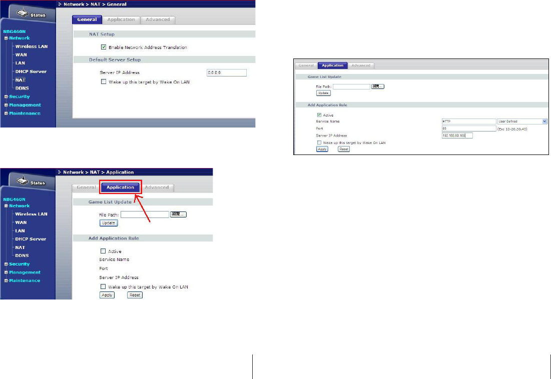
4. Enable Network Address Translation (NAT) service.
5. Select “Application”
6. In the application page, key in the Gateway IP address information as following
example.
*Select “HTTP” as Service Name.
*Select Port 80 as your Gateway port selection
*Key in the IP address of the gateway
*Press apply to finish NAT setup
7. Once NAT service of the router is setup, user can access the gateway
anywhere from internet by opening IE web browser and key in the fix public
IP address provided by your internet service provider
GREEN POWERLINK On-Line Energy Management Solution V1.0
28
GREEN POWERLINK On-Line Energy Management Solution V1.0
29
8. The NAT service of the router will redirect your access request to the
corresponding Gateway.
CAUTION:
To assure continued FCC compliance:
Any changes or modifications not expressly approved by the grantee of this device
could void the user's authority to operate the equipment.
GREEN POWERLINK On-Line Energy Management Solution V1.0
30
GREEN POWERLINK On-Line Energy Management Solution V1.0
31
!