Powerwave Technologies 5JS0042 Linear Feed-Forward Power Amplifier User Manual Part 2
Powerwave Technologies Inc Linear Feed-Forward Power Amplifier Part 2
UserManual.wiki
>
Powerwave Technologies
>
5JS0042 User Manual
>
User Manual Part 2
Contents
1.
User Manual Part 1
2.
User Manual Part 2
3.
User Manual Part 3
4.
User Manual Part 4
5.
User Manual Part 5
6.
User Manual Part 6
7.
User Manual Part 7
8.
User Manual Part 8
User Manual Part 2
Navigation menu
Upload a User Manual
Namespaces
Wiki Guide
HTML
PDF
Info
Views
User Manual
Discussion / Help
Navigation
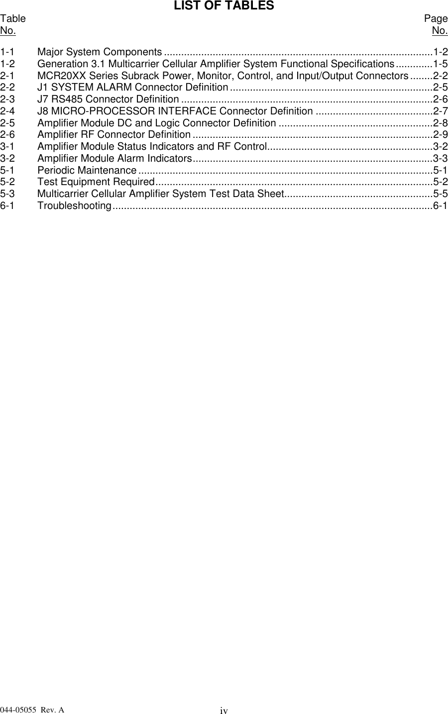
![044-05055 Rev. A iiiTABLE OF CONTENTS (Continued)Par. Section 5 PageNo. Maintenance No.5-1 Introduction.......................................................................................................................5-15-2 Periodic Maintenance .......................................................................................................5-15-3 Test Equipment Required For Test ..................................................................................5-15-4 Cleaning Air Inlets/Outlets ................................................................................................5-25-5 Performance Test.............................................................................................................5-25-5.1 Amplifier System Performance Test.................................................................................5-25-6 Field Replaceable Parts and Modules..............................................................................5-65-6.1 G3X-800 Series (NTL107AA) Power Amplifier Module....................................................5-65-6.2 Cooling Fans ....................................................................................................................5-6Section 6Troubleshooting6-1 Introduction.......................................................................................................................6-16-2 Troubleshooting................................................................................................................6-16-3 Return for Service Procedure...........................................................................................6-16-3.1 Obtaining an RMA ............................................................................................................6-16-3.2 Repackaging for Shipment ...............................................................................................6-1LIST OF ILLUSTRATIONSFigure PageNo. No.1-1 G3X-800 Series (NTL107AA) Amplifier............................................................................1-31-2 MCR20XX Series (NTL107AC) Subrack with Two Amplifiers..........................................1-42-1 MCR20XX Series (NTL107AC) Subrack, Rear View .......................................................2-32-2 J1 SYSTEM ALARM Connector .......................................................................................2-52-3 J7 RS485 Connector ........................................................................................................2-62-4 J8 MICRO-PROCESSOR INTERFACE Connector .........................................................2-72-5 DC and Logic Connector [on Rear of G3X-800 Series (NTL107AA) Amplifier Module]...2-82-6 Amplifier RF Connector ....................................................................................................2-93-1 G3X-800 Series (NTL107AA) Amplifier Module Control and Indicators...........................3-14-1 MCR20XX Series (NTL107AC) Two Module Amplifier System .......................................4-24-2 G3X-800 Series (NTL107AA) Power Amplifier Module Functional Block Diagram..........4-35-1 Amplifier System Test Setup Diagram .............................................................................5-3](https://usermanual.wiki/Powerwave-Technologies/5JS0042.User-Manual-Part-2/User-Guide-74209-Page-2.png)