Powerwave Technologies 5JS0042 Linear Feed-Forward Power Amplifier User Manual Part 4
Powerwave Technologies Inc Linear Feed-Forward Power Amplifier Part 4
UserManual.wiki
>
Powerwave Technologies
>
5JS0042 User Manual
>
User Manual Part 4
Contents
1.
User Manual Part 1
2.
User Manual Part 2
3.
User Manual Part 3
4.
User Manual Part 4
5.
User Manual Part 5
6.
User Manual Part 6
7.
User Manual Part 7
8.
User Manual Part 8
User Manual Part 4
Navigation menu
Upload a User Manual
Namespaces
Wiki Guide
HTML
PDF
Info
Views
User Manual
Discussion / Help
Navigation

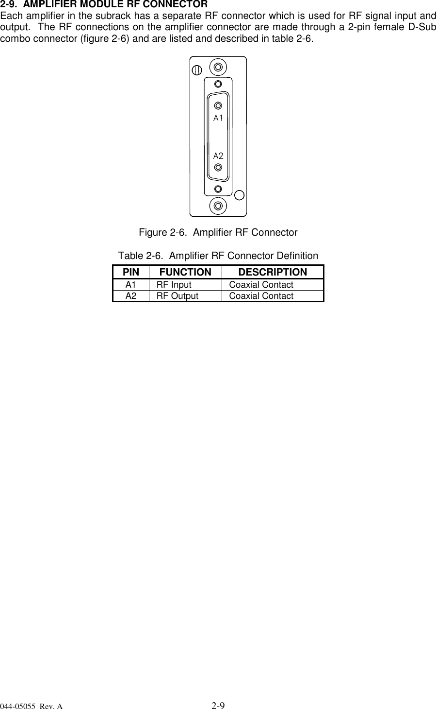
![044-05055 Rev. A 2-82-8. AMPLIFIER MODULE STATUS, ALARM, CONTROL, AND POWER CONNECTOREach amplifier in the subrack has a separate remote alarm and control connector which may beused by the host system to monitor and control the individual amplifier modules. The status,alarm, control, and power connections on the amplifier connector are made through a 21-pin maleD-Sub combo connector (figure 2-5) and are listed and described in table 2-5.Figure 2-5. DC and Logic Connector [on Rear of G3X-800 Series (NTL107AA) Amplifier Module]Table 2-5. Amplifier Module DC and Logic Connector DefinitionPIN FUNCTION DESCRIPTIONA1 Power Input +27 Vdc (Power Contact)A2 Power Input +27 Vdc (Power Contact)A3 Ground Ground (Power Contact)A4 Ground Ground (Power Contact)1 RS485 +TxD Serial Communication Data Out2 RS485 +RxD Serial Communication Data In3 Service Loop TTL input to Amp. Gnd. for special test mode (Note 1)4 MCPA Disabled(Summary Fault) TTL signal normally low indicates MCPA enabled. A high levelindicates that the MCPA has been disabled. Over Power, OverVoltage takes one second to activate the signal.5 Mod Addr 0 TTL input to Amp. Gnd. supplied by shelf to identify slot.6 Mod Addr 1 TTL input to Amp. Gnd. supplied by shelf to identify slot.7 TP1 TTL output. Future test point.8 Manual Download GND to download manually9 DC on stat TTL output. High indicates Amp is powered on.10 RS485 –TxD Serial Communication Data Out11 RS485 –RxD Serial Communication Data In12 SCL7 No connection13 SDA7 No connection14 FP Disable Output Output, GND if the front panel switch is in the OFF position; +5 voltsindicates the front panel switch is in the ON position.15 FP RST Output, GND if the front panel switch is in the RESET position; +5 voltsotherwise.16 GND Ground17 Module Detect Ground potential. Informs the subrack that an MCPA is plugged in.Note 1: Service loop grounded allows the MCPA to be enabled or disabled by the front panelswitch when not mounted in the shelf.](https://usermanual.wiki/Powerwave-Technologies/5JS0042.User-Manual-Part-4/User-Guide-74211-Page-8.png)