Powerwave Technologies 5JS0042 Linear Feed-Forward Power Amplifier User Manual Part 4
Powerwave Technologies Inc Linear Feed-Forward Power Amplifier Part 4
Contents
User Manual Part 4

044-05055 Rev. A 2-1
INSTALLATION
2-1. INTRODUCTION
This section contains installation recommendations, unpacking, inspection, and installation
instructions for the Multicarrier Cellular Amplifier System. Carefully read all material in this section
prior to equipment unpacking or installation. Also read and review the operating procedures in
Section 3 prior to installing the equipment. Section 3 contains applicable standards imposed by
the Federal Communications Commission. It is important that the licensee perform these tasks
correctly and in good faith. Carefully read Parts 73 and 74 of the FCC rules to determine how
they apply to your installation. DON'T TAKE CHANCES WITH YOUR LICENSE.
2-2. ELECTRICAL SERVICE RECOMMENDATIONS
Powerwave Technologies recommends that proper AC line conditioning and surge suppression
be provided on the primary AC input to the +27 Vdc power source. All electrical service should be
installed in accordance with the National Electrical Code, any applicable state or local codes, and
good engineering practice. Special consideration should be given to lightning protection of all
systems in view of the vulnerability of most transmitter sites to lightning. Lightning arrestors are
recommended in the service entrance. Straight, short ground runs are recommended. The
electrical service must be well grounded.
Each amplifier system should have its own circuit breaker, so a failure in one does not shut off the
whole installation. Circuit breakers should be thermal type, capable of handling the anticipated
inrush current, in a load center with a master switch.
2-3. UNPACKING AND INSPECTION
This equipment has been operated, tested, and calibrated at the factory. Only in the event of
severe shocks or other mistreatment should any substantial readjustment be required. Carefully
open the containers and remove the subrack and amplifier modules. Retain all packing material
that can be reassembled in the event that the unit must be returned to the factory.
CAUTION
Exercise care in handling equipment
during inspection to prevent damage
caused by rough or careless handling.
Visually inspect the amplifier subrack and modules for damage that may have occurred during
shipment. Check for evidence of water damage, bent or warped chassis, loose screws or nuts, or
extraneous packing material in connectors or fans. Inspect all connectors for bent connector pins.
If the equipment is damaged, a claim should be filed with the carrier once the extent of any
damage is assessed. We cannot stress too strongly the importance of IMMEDIATE careful
inspection of the equipment and the subsequent IMMEDIATE filing of the necessary claims
against the carrier if necessary. If possible, inspect the equipment in the presence of the delivery
person. If the equipment is damaged, the carrier is your first area of recourse. If the equipment is
damaged and must be returned to the factory, write or phone for a return authorization.
Powerwave may not accept returns without a return authorization. Claims for loss or damage may
not be withheld from any payment to Powerwave, nor may any payment due be withheld pending
the outcome thereof. WE CANNOT GUARANTEE THE FREIGHT CARRIER'S PERFORMANCE.
Section
2

044-05055 Rev. A 2-2
2-4. INSTALLATION INSTRUCTIONS
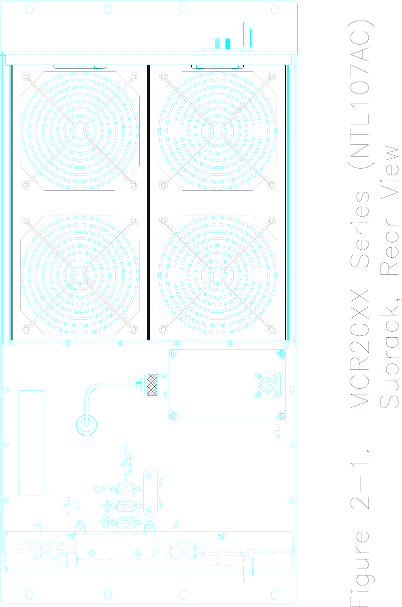
The MCR20XX Series (NTL107AC) 23-inch subrack, which holds two amplifier modules, is
designed for installation in a rack or cabinet that permits access to the rear of the amplifier system
for connection of DC power, RF, and control and monitor cables. The location and function of the
system interface connectors are shown in figures 2-1, 2-2, 2-3, and 2-4, and are described in
tables 2-1, 2-2, 2-3, and 2-4. The plug-in amplifier module connectors are shown in figures 2-5
and 2-6, and are described in tables 2-5 and 2-6.
Table 2-1. MCR20XX Series Subrack Power, Monitor, Control, and Input/Output Connectors
NO. NAME FUNCTION
J1 SYSTEM ALARM Connector 9-Pin female D-Sub connector. Form C alarms. Refer
to figure 2-2 and table 2-2 for individual pin signals.
J2 R
RF
F
O
OU
UT
T
C
Co
on
nn
ne
ec
ct
to
or
r Type N female coax connector. Output to antenna.
Refer to table 1-2 for power output level of one or two
amplifier module systems.
J3 +27V Connector Two ¼-20 Studs, +27 Vdc power input, MCPA #1
J4 RTN connector Two ¼-20 Studs, power return, MCPA #1
J5 +27V Connector Two ¼-20 Studs, +27 Vdc power input, MCPA #2
J6 RTN Two ¼-20 Studs, power return, MCPA #2
J7 RS485 Connector 9-Pin female D-Sub connector. RS-485/Addressing
serial communication. Refer to figure 2-3 and table
2-3 for individual pin signals.
J8 MICRO-PROCESSOR
INTERFACE Connector 9-Pin female D-Sub connector. RS-485 and RS-232
serial communication. Refer to figure 2-4 and table
2-4 for individual pin signals.
J9 RF INPUT Connector SMA female coax connector. Refer to table 1-2 for
power input level to amplifier module system.
To install the amplifier system proceed as follows:
1. Insert subrack in equipment rack or cabinet and secure in place with eight screws
2. Refer to figure 2-1 for the location of all subrack input/output connectors.
3. Connect antenna cable to J2 RF OUT type N connector on rear of subrack.
WARNING
Turn off external primary DC power before
connecting DC power cables.
4. Remove protective cover over power terminal studs; do not discard. Connect positive primary
power for MCPA #1 (the upper amplifier) to J3 +27V studs and negative primary power
(return) to J4 RTN studs. Connect positive primary power for MCPA #2 (the lower amplifier)
to J5 +27V studs and negative primary power (return) to J6 RTN studs. Tighten all
connections.
WARNING
Replace protective cover over power terminal studs.
Failure to replace cover properly could result in
personal injury and damage to equipment in the
event of a short circuit.
5. Connect transceiver or exciter output to J9 RF IN SMA-type connector on the rear of the
subrack.
044-05055 Rev. A 2-3

044-05055 Rev. A 2-4
6. As required by the specific facility, one or more of the following cables should be connected:
• Connect alarms monitor cable to J1 SYSTEM ALARM connector on rear of subrack (refer
to figure 2-2 and table 2-2 for J1 SYSTEM ALARM connector definition).
• Connect RS-485 control cable to J7 RS-485 connector on rear of subrack (refer to figure
2-3 and table 2-3 for J7 RS-485 connector definition).
• Connect computer interface cable to J8 MICRO-PROCESSOR INTERFACE connector
on rear of subrack (refer to figure 2-4 and table 2-4 for J8 MICRO-PROCESSOR
INTERFACE definition).
CAUTION
Verify that the power circuit breaker switches on the
front panels of the amplifiers are in the right (OFF)
position, and that the RF ON switches are in the
down (Off) position.
7. Install the plug-in amplifier modules in the slots of the subrack.
8. Check your work before applying DC voltage to the system. Make certain all connections are
tight and correct.
9. Measure primary DC input voltage at the power distribution panel. DC input voltage should be
+27 Vdc ±1.0 Vdc.
10. Refer to section 3 for initial turn-on and checkout procedures.
044-05055 Rev. A 2-5
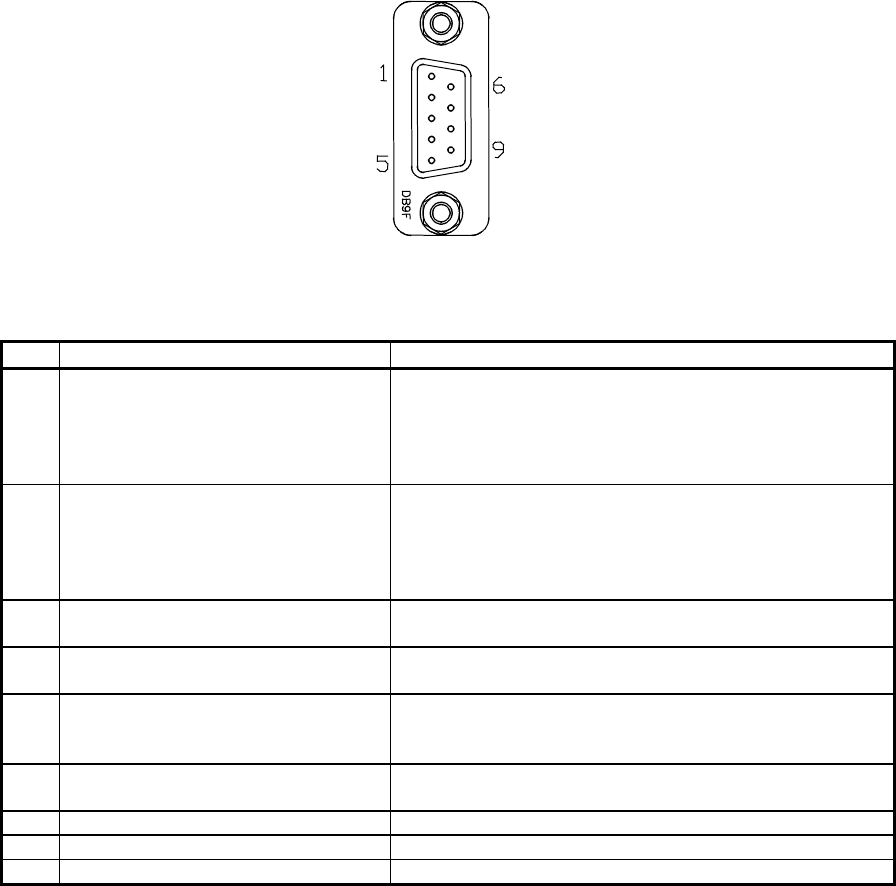
2-5. J1 SYSTEM ALARM CONNECTOR
The J1 SYSTEM ALARM connector on the rear of the MCR20XX Series (NTL107AC) subrack is
a 9-pin female D-sub connector that permits monitoring various alarm signals for each amplifier in
the subrack. Refer to figure 2-2 and table 2-2 for connector definition.
Figure 2-2. J1 SYSTEM ALARM Connector
Table 2-2. J1 SYSTEM ALARM Connector Definition
PIN ALARM INDICATION DESCRIPTION
1 Critical (MCPA 1 shuts down) Under normal operation, pulled up to the 27-volt line
through a 1000-ohm resistor. Opens when both fans
fail or when the following alarms trigger for module #1:
Over Pwr, High Temp, VSWR, DC Fail, Loop Fail, or
Low Pwr.
2 Critical (MCPA 2 shuts down) Under normal operation, pulled up to the 27-volt line
through a 1000-ohm resistor. Opens when both fans
fail or when the following alarms trigger for module #2:
Over Pwr, High Temp, VSWR, DC Fail, Loop Fail, or
Low Pwr.
3 Major 1 (any one of 4 fan fail on
MCPA #1) Under normal operation, pulled up to the 27-volt line
through a 1000-ohm resistor.
4 Major 2 (any one of 4 fan fail on
MCPA #2) Under normal operation, pulled up to the 27-volt line
through a 1000-ohm resistor.
5 Enable (Complete MCPA system
shuts down) Pulled to 27 volts through 630 ohms if one or more
modules are active. If no modules are active, then
pulled to ground through 1000 ohms.
6 APC Under normal operation, pulled up to the 27-volt line
through a 1000-ohm resistor.
7 No Connection
8 No Connection
9 Common Ground

044-05055 Rev. A 2-6
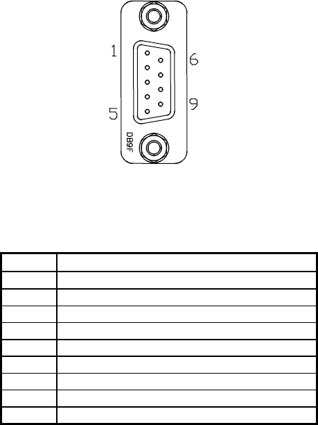
2-6. J7 RS485 CONNECTOR
The J7 RS485 connector on the rear of the MCR20XX Series (NTL107AC) subrack is a 9-pin
female D-sub connector that permits serial interface with the MCPA system. Refer to figure 2-3
and table 2-3 for connector definition.
Figure 2-3. J7 RS485 Connector
Table 2-3. J7 RS485 Connector Definition
PIN DESCRIPTION
1 RS-485 Rx+
2 Addr 0
3 Addr 1
4 RS-485 Rx–
5 Ground
6 RS-485 Tx–
7 RS-485 Tx+
8 Addr 2
9 Addr 3
044-05055 Rev. A 2-7
2-7. J8 MICRO-PROCESSOR INTERFACE CONNECTOR
The J8 MICRO-PROCESSOR INTERFACE connector on the rear of the MCR20XX Series
(NTL107AC) subrack is a 9-pin female D-sub connector that permits serial interface with the
MCPA system. Refer to figure 2-4 and table 2-4 for connector definition. J8 will be used for the
initialization process of this system.
Figure 2-4. J8 MICRO-PROCESSOR INTERFACE Connector
Table 2-4. J8 MICRO-PROCESSOR INTERFACE Connector Definition
PIN DESCRIPTION
1 RS-485 Rx+
2 RS-232 Rx
3 RS-232 Tx
4 RS-485 Rx–
5 Ground
6 RS-485 Tx–
7 RS-485 Tx+
8 Select
9 Ground
044-05055 Rev. A 2-8
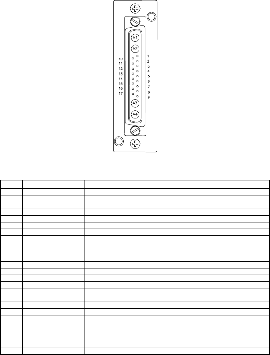
2-8. AMPLIFIER MODULE STATUS, ALARM, CONTROL, AND POWER CONNECTOR
Each amplifier in the subrack has a separate remote alarm and control connector which may be
used by the host system to monitor and control the individual amplifier modules. The status,
alarm, control, and power connections on the amplifier connector are made through a 21-pin male
D-Sub combo connector (figure 2-5) and are listed and described in table 2-5.
Figure 2-5. DC and Logic Connector [on Rear of G3X-800 Series (NTL107AA) Amplifier Module]
Table 2-5. Amplifier Module DC and Logic Connector Definition
PIN FUNCTION DESCRIPTION
A1 Power Input +27 Vdc (Power Contact)
A2 Power Input +27 Vdc (Power Contact)
A3 Ground Ground (Power Contact)
A4 Ground Ground (Power Contact)
1 RS485 +TxD Serial Communication Data Out
2 RS485 +RxD Serial Communication Data In
3 Service Loop TTL input to Amp. Gnd. for special test mode (Note 1)
4 MCPA Disabled
(Summary Fault) TTL signal normally low indicates MCPA enabled. A high level
indicates that the MCPA has been disabled. Over Power, Over
Voltage takes one second to activate the signal.
5 Mod Addr 0 TTL input to Amp. Gnd. supplied by shelf to identify slot.
6 Mod Addr 1 TTL input to Amp. Gnd. supplied by shelf to identify slot.
7 TP1 TTL output. Future test point.
8 Manual Download GND to download manually
9 DC on stat TTL output. High indicates Amp is powered on.
10 RS485 –TxD Serial Communication Data Out
11 RS485 –RxD Serial Communication Data In
12 SCL7 No connection
13 SDA7 No connection
14 FP Disable Output Output, GND if the front panel switch is in the OFF position; +5 volts
indicates the front panel switch is in the ON position.
15 FP RST Output, GND if the front panel switch is in the RESET position; +5 volts
otherwise.
16 GND Ground
17 Module Detect Ground potential. Informs the subrack that an MCPA is plugged in.
Note 1: Service loop grounded allows the MCPA to be enabled or disabled by the front panel
switch when not mounted in the shelf.
044-05055 Rev. A 2-9
2-9. AMPLIFIER MODULE RF CONNECTOR
Each amplifier in the subrack has a separate RF connector which is used for RF signal input and
output. The RF connections on the amplifier connector are made through a 2-pin female D-Sub
combo connector (figure 2-6) and are listed and described in table 2-6.
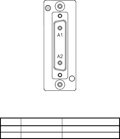
Figure 2-6. Amplifier RF Connector
Table 2-6. Amplifier RF Connector Definition
PIN FUNCTION DESCRIPTION
A1 RF Input Coaxial Contact
A2 RF Output Coaxial Contact