Powerwave Technologies 5JS0042 Linear Feed-Forward Power Amplifier User Manual Part 3
Powerwave Technologies Inc Linear Feed-Forward Power Amplifier Part 3
Contents
User Manual Part 3

044-05055 Rev. A 1-1
GENERAL DESCRIPTION
1-1. INTRODUCTION
This manual contains information and procedures for installation, operation, and maintenance of
Powerwave’s Generation 3.1 amplifier system. The manual is organized into six sections as
follows:
Section 1. General Description
Section 2. Installation
Section 3. Operating Instructions
Section 4. Principles of Operation
Section 5. Maintenance
Section 6. Troubleshooting
1-2. GENERAL DESCRIPTION
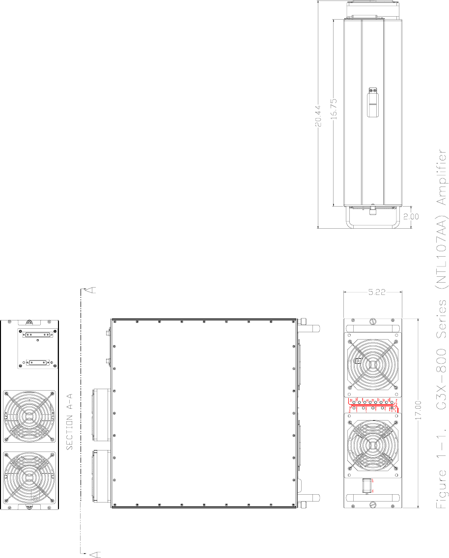
The G3X-800 Series (NTL107AA) amplifier (figure 1-1) is a linear, feed-forward power amplifier
that operates in the 25-MHz frequency band from 869 MHz to 894 MHz. The amplifier can
simultaneously transmit multiple frequencies, with better than -65 dBc third order intermodulation
distortion (IMD). The amplifier system is modular in design, and is ideally suited for use in
AMPS/TDMA/CDMA base stations. The plug-in G3X-800 Series (NTL107AA) amplifier modules
can each provide 110 watts of power and function completely independently of each other. The
amplifier modules are designed for parallel operation to produce high peak power output and
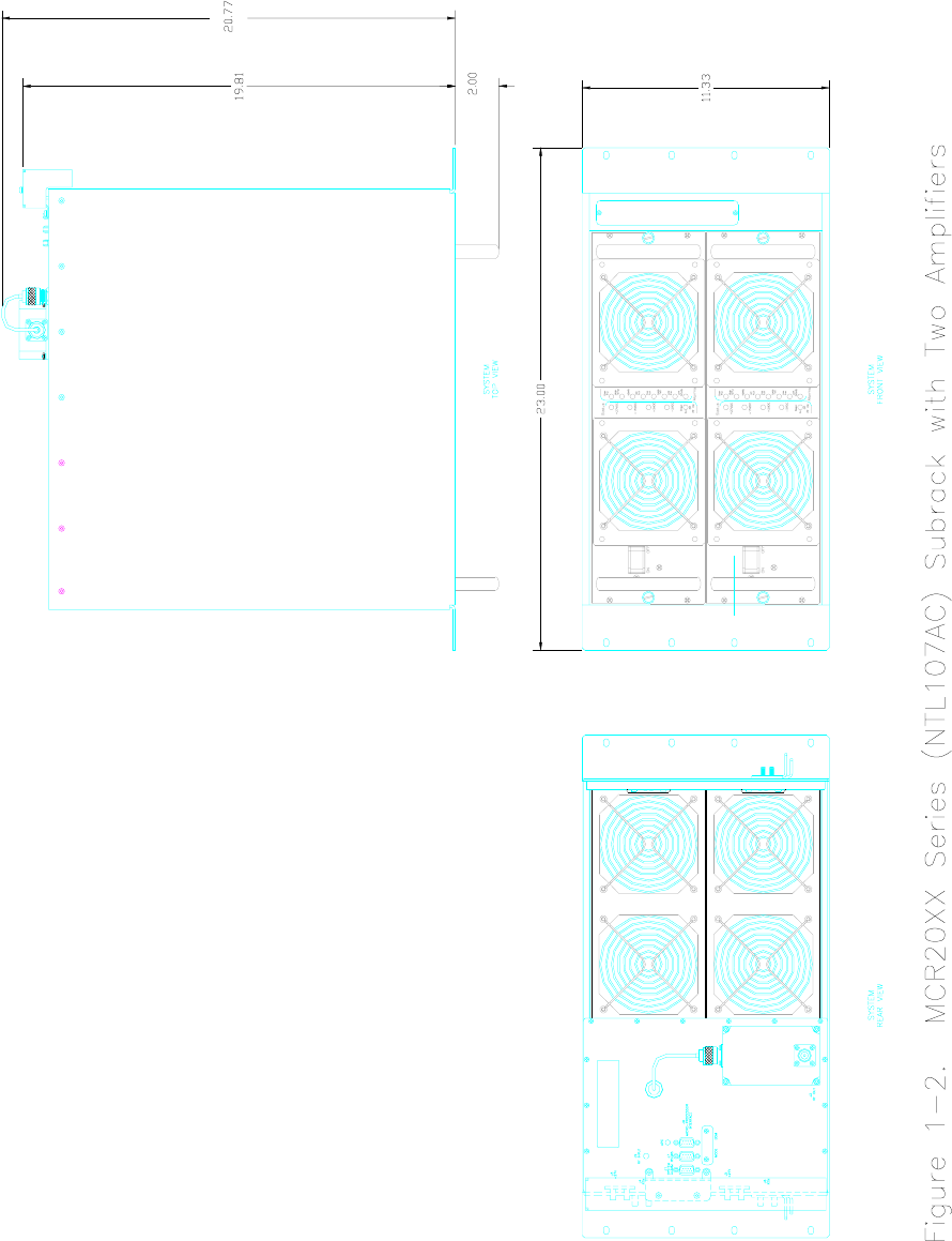
backup redundancy for remote applications. The system is housed in the MCR20XX Series
(NTL107AC) subrack (figure 1-2) which holds two G3X-800 Series (NTL107AA) amplifiers to
produce up to 200 watts output. All solid-state, the system is designed to provide trouble-free
operation with minimum maintenance. The system's modular construction and unique and highly
effective LED-based operational status and fault indicators help minimize downtime. The turn-on
and turn-off sequences of voltages are fully automatic, as is overload protection and recycling.
Inadvertent operator damage from front panel manipulation is virtually impossible.
Notice
To comply with FCC regulations, no
channels existing within 200 kHz spacing
from the edges of any frequency block are to
be used for transmission.
The MCR20XX Series (NTL107AC) subrack contains an RF power splitter/combiner and a control
module that monitors the functional status of all plug-in amplifiers. The rear panel of the subrack
has the system RF I/O connectors and DC power input terminals. The front panel of each
amplifier module has unit level status/fault indicators and a power on/off circuit breaker. Primary
power for the amplifier system is +27 Vdc. Cooling for each plug-in amplifier module is provided
by two fans mounted on the front and two on the rear of the module. The fans draw outside air
through the front of the module and exhaust hot air out through the rear of the module.
Section
1

044-05055 Rev. A 1-2
1-3. FUNCTIONAL AND PHYSICAL SPECIFICATIONS
Functional and physical specifications for the amplifier system are listed in table 1-2.
1-4. EQUIPMENT CHANGES
Powerwave Technologies, Inc. reserves the right to make minor changes to the equipment,
including but not necessarily limited to component substitution and circuitry changes. Changes
that impact this manual may subsequently be incorporated in a later revision of this manual.
1-5. ORDERING INFORMATION
Table 1-1 following gives the part numbers and descriptions to be used when ordering either an
entire system or individual major components that comprise the system.
Table 1-1. Major System Components
SYSTEM
ORDER
NUMBER
DESCRIPTION OF
SYSTEM NUMBER SUB-
COMPONENT
MODEL
NUMBER
QTY
PER
SYSTEM
DESCRIPTION OF SUB-
COMPONENT MODEL
NUMBER
MCR20XX
Series
(NTL107AC)
200 W 869-894 MHz Linear
System for Base Station
Equipment.
MCR20XX
Series
(NTL107AC)
1 2-Unit 23” Subrack.
G3X-800
Series
(NTL107AA)
2 110 W 869-894 MHz Amplifier
Module.
800-00972-001 4 Front fan assembly (Intake)
800-00972-002 4 Rear fan assembly (Exhaust)
044-05055 Rev. A 1-3
044-05055 Rev. A 1-4

044-05055 Rev. A 1-5
Table 1-2. Generation 3.1 Multicarrier Cellular Amplifier System Functional Specifications
Frequency Range: 869-894 MHz
Total Output Power (Minimum) in
MCR20XX (NTL107AA) System: 110 W typical (1 Module)
200 W typical (2 Modules)
Maximum Input Power Overdrive fault activates when input power >5 dBm
Intermodulation Distortion
and In-Band Spurious: -68 dBc (Typical) @ +24 to +28 Vdc @ 200 Watts
(-65 dBc (Max) @ +21.7 to +24 Vdc)
Nominal RF Gain: 31 ±1 dB to 49 ±1 dB Adjustable
Gain Variation: ± 0.6 dB @ 27 Vdc ±1 Vdc
+ 0.6 / -0.8 dB @ 24 to 26 Vdc
Output Port Return Loss: 16 dB (Min)
Output Protection: Mismatch Protected (Isolator)
Input Port Return Loss: 16 dB (Min)
Second Harmonic: -13 dBm (Max)
Out of Band Spurious: -60 dBc (Max) @ +24 to +28 Vdc
DC Input Voltage: 21.7 to 30 Vdc (24 to 28 Vdc for rated operation)
DC Input Current: 110 Amps (Typical) @ 27 ±1 Vdc Input, 200 Watts
PA Self Protection: MCA Disabled Upon 5-Second Continuous Alarm
Operating Temperature: -5 ºC to +60 ºC Ambient
Storage Temperature: -40 ºC to +85 ºC
Operating Humidity: 5% - 95% Relative Humidity (Noncondensing)
Storage Humidity: 0% - 95 % Relative Humidity (Noncondensing)
Connectors
DC Power:
RF INPUT:
RF OUT (Antenna):
SYSTEM ALARM:
RS-485
MICROPROCESSOR INTERFACE
¼-20 studs
SMA
Type N
9-Pin D-Subminiature Female
9-Pin D-Subminiature Female
9-Pin D-Subminiature Female
Alarms Over Power, VSWR, DC Failure, High Temperature, Loop
Failure, Fan Failure
Monitors Forward Power and Reverse Power
Dimensions:
G3X-800 Series (NTL107AA)
Amplifier:
MCR20XX Series
(NTL107AC) Subrack:
5.22" High, 17.00” Wide, 20.44” Deep
(Including handles, rear fans)
11.33” High, 23.00” Wide, 22.77” Deep
(With amplifiers inserted)