Powerwave Technologies 5JS0042 Linear Feed-Forward Power Amplifier User Manual Part 6
Powerwave Technologies Inc Linear Feed-Forward Power Amplifier Part 6
Contents
User Manual Part 6

044-05055 Rev. A 4-1
PRINCIPLES OF OPERATION
4-1. INTRODUCTION
This section contains a functional description of the Multicarrier Cellular Amplifier System.
4-2. RF INPUT SIGNAL
The maximum input power for all carrier frequencies should not exceed the limits specified in
table 1-2. For proper amplifier loop balance, the out of band components of the input signals
should not exceed -60 dBc. The input VSWR should be 2:1 maximum (or better).
4-3. RF OUTPUT LOAD
The load impedance should be as good as possible (1.5:1 or better) in the working band for good
power transfer to the load. If the amplifier is operated into a filter, it will maintain its distortion
characteristics outside the signal band even if the VSWR is infinite, provided the reflected power
does not exceed one watt. A parasitic signal of less than one watt incident on the output will not
cause distortion at a higher level than the normal forward distortion (i.e. -60 dBc).
4-4. SYSTEM FUNCTIONAL DESCRIPTION
The amplifier system is comprised of an MCR20XX Series (NTL107AC) subrack and one or two
G3X-800 Series (NTL107AA) plug-in power amplifier modules. The G3H-800 amplifier is a linear,
feed-forward power amplifier that operates in the 25 MHz frequency band from 869 to 894 MHz.
A typical two module system is shown in figure 4-1. Power output specifications for a one or two
module system are listed in table 1-2. Each amplifier is a self-contained plug-in module and is
functionally independent of other amplifier modules. The amplifier modules are designed for
parallel operation to achieve high peak power output, and for redundancy in unmanned remote
locations. The subrack houses a two-way splitter and active power combiner, control assembly,
true RMS detector, and back-plane/in-rush current assembly. The rear panel of the subrack has
I/O connectors that interface with the host system, RF signal source, system antenna, and the
system DC power source. The amplifier system can simultaneously transmit multiple carrier
frequencies, at an average total power output of 110 watts (one amplifier module in a subrack
unit) to 200 watts (two amplifier modules), with -68 dBc third order intermodulation distortion
(IMD).
A composite RF signal from the base station radios is applied to the RF input (J9) of the subrack.
From there the signal passes through a voltage variable attenuator (VVA), then a two-way splitter.
Each leg of the splitter passes through an isolator, then the blind-mate connector to interface with
the MCPA. The signal then returns to the subrack via the blind-mate connector after being
amplified by the MCPA modules. The two high-power signals are combined by the active power
combiner. The active power combiner has the capability of switching MCPA channels off-line by
the use of RF switches. If an MCPA is not present, turned off, or faulted, the switch will open in
that channel and physically disconnect that MCPA. The combiner maintains its low insertion
characteristics when used in the single path configuration. Note that the splitter is not switched,
therefore the power is automatically reduced by 3 dB, thus eliminating an output overdrive
condition. The output of the combiner is fed through a coupler, then a receive-band filter. The
amplified RF signal is available for use at the output of the receive-band filter (J2). The coupler is
used to sample the output power to the true RMS detector. The true RMS detector will supply the
microcontroller with an accurate average power regardless of the signal modulation type. The
Section
4
044-05055 Rev. A 4-2
dynamic range is 25 dB. The power reading is used during the gain initialization phase when
deploying the system or monitoring to detect excessive output power. In both cases the VVA will
be adjusted accordingly. Two non-RF features of the subrack system are inrush current limiting
and alarm status/serial interface ports. The inrush current limiting circuitry is used to minimize the
instantaneous current demand when the MCPA is first DC powered-up. This is due to the high
capacitance on the MCPA’s DC input. The circuit is placed in series on the DC source before the
MCPA. Voltage for the subrack is derived prior to the in-rush current limit circuitry. The circuitry is
in a high impedance state upon DC power-up. When an MCPA is enabled the impedance is
slowly brought down to nearly 0 ohms. This will allow the capacitors to charge over a longer
period of time, thus reducing the high current drain on the power supply. The three ports on the
rear of the subrack are for Form-C alarms (J1), RS485/Addressing serial communication (J7) and
RS485 and RS232 serial communication (J8). The J1, J7, and J8 connectors are detailed in
chapter 2 (see figures 2-2, 2-3, and 2-4, and tables 2-2, 2-3, and 2-4). The serial interface allows
the user to acquire MCPA internal voltages and status, exercise MCPA and VVA control, upgrade
MCPA or subrack firmware, and obtain true RMS power readings.
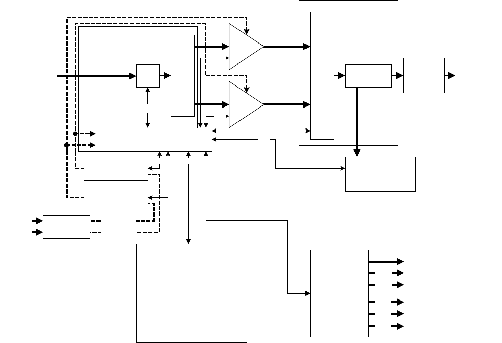
Figure 4-1. MCR20XX Series (NTL107AC) Two Module Amplifier System
4-5. MCR20XX Series (NTL107AC) SUBRACK
The MCR20XX Series (NTL107AC) subrack (see block diagram figure 4-1) is not field repairable.
The subrack functions are described in section 4-4.
RF IN J9 VVA COUPLER BPF
ALC_LED
MOD PORT
BDM PORT
RF OUT J2
J8
RS485/ADD.
RS485/RS232
RMS DET.
500-001090
J5/J6
J3/J4
INTERFACE
ASSY.
500-1107
POWER SPLITTER
FORM C ALARMS
J7
SIGNAL DISTRIBUTION
17
17
ACTIVE POWER COMBINER
MCA 1
MCA 2
IN-RUSH
IN-RUSH
DC_CH1
DC_CH2
SPLITTER &
SIGNAL DIST.
ASSY.
500-001095
80A MAX
80A MAX
DB9
DB9
J1
DB9
2X3
2X3
2
12
4
COMBINER
ASSY
500-001094
5 5
CONTROL
ASSEMBLY
500-001105
100 30
044-05055 Rev. A 4-3
4-6. G3X-800 SERIES (NTL107AA) AMPLIFIER MODULE
The amplifier module, figure 4-2, has an average power output of 110 watts with intermodulation
products suppressed to better than -65 dBc below carrier levels. The amplifier provides an
amplified output signal with constant gain and phase by adding approximately 30 dB of distortion
cancellation on the output signal. Constant gain and phase is maintained by continuously
comparing active paths with passive references, and correcting for small variations through the
RF feedback controls. All gain and phase variations, for example those due to temperature, are
reduced to the passive reference variations. The amplifier module is comprised of:
Delay lines
Couplers
Preamplifiers
Main amplifier
Error amplifier
Two feed-forward loops with phase-shift and gain controls
DC/DC power regulator
Alarm monitoring, control and display panel
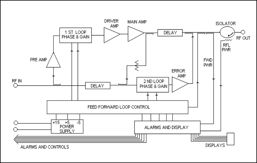
Figure 4-2. G3X-800 Series (NTL107AA) Power Amplifier Module Functional Block Diagram
The main amplifier employs class AB amplification for maximum efficiency. The error amplifier
and feed forward loops are employed to correct signal nonlinearities introduced by the class AB
main amplifier. The error amplifier operates in class AB mode. The RF input signals are coupled
and amplified by a preamp, then fed to an attenuator and phase shifter in the first feedforward
loop. The main signal is phase shifted by 180 degrees and amplified in the premain amplifier.
The output from the driver amplifier is fed to the class AB main amplifier. The output from the
main amplifier is typically 160 watts. The signal is output to several couplers and a delay line.
The signal output from the main amplifier is sampled using a coupler, and the sample signal is
combined with the main input signal and input to the second feed-forward loop. The error signal is
attenuated, phase shifted 180 degrees, then fed to the error amplifier where it is amplified to a
level identical to the sampled output from the main amplifier. The output from the error amplifier
044-05055 Rev. A 4-4
is then coupled back and added to the output from the main amplifier. The control loops
continuously make adjustments to cancel out any distortion in the final output signals.
The primary function of the first loop is to provide an error signal for the second loop. The primary
function of the second loop is to amplify the error signal to cancel out spurious products
developed in the main amplifier. The input signal is fed to a coupler and delay line. The signal
from the coupler is amplified by a preamplifier and fed to the attenuator and phase shifter in the
first loop. The first loop control section phase shifts the main input signals by 180 degrees and
constantly monitors the output for correct phase and gain.
The second loop control section obtains a sample of the distortion added to the output signals by
the main amplifier, phase shifts the signals by 180 degrees, then feeds it to the error amplifier. It
is then amplified to the same power level as the input sample and coupled onto the main output
signal. The final output is monitored by the second loop and adjusted to ensure that the signal
distortion and IMD on the final output is canceled out.
4-6.1. MAIN AMPLIFIER
The input and output of the amplifier employ two-stage, class AB amplifiers which provide
approximately 25 dB of gain in the 25 MHz frequency band from 869 to 894 MHz. The amplifier
operates on +27 Vdc, and a bias voltage of +5 Vdc, and is mounted directly on a heat sink which
is temperature monitored by a thermostat. If the heat sink temperature exceeds 85 °C, the
thermostat opens and a high temperature fault occurs. The alarm logic controls the +5 Vdc bias
voltage which shuts down the amplifier.
4-6.2. ERROR AMPLIFIER
The main function of the error amplifier is to sample and amplify the signal distortion level
generated by the main amplifier, to a level that cancels out the distortion and IMD when the error
signal is coupled onto the main signal at the amplifier output. The error amplifier is a balanced
multistage, class AB amplifier, has 51 dB of gain and produces an 80-watt output. The amplifier
operates on 27 Vdc and a bias voltage of +5 Vdc, and is mounted directly on a heat sink.
4-6.3. AMPLIFIER MONITORING
In the main and error amplifier modules, all normal variations are automatically compensated for
by the feedforward loop control. However, when large variations occur beyond the adjustment
range of the loop control, a loop fault will occur. The alarms are displayed on the front panel
indicators and output via a 21-pin connector on the rear of the module to the subrack summary
board for subsequent remote monitoring via the ALARMS connector. Refer to paragraph 2-5 as
well as figure 2-2 and table 2-2 for a description of the ALARMS connector.
4-6.4. AMPLIFIER MODULE COOLING
Although each amplifier module contains its own heat sink, it is cooled with forced air. Four fans
are used for forced air cooling and redundancy. The fans, located on the front and rear of the
amplifier module, draw air in through the front of the amplifier and exhaust hot air out the back of
the module. The fans are field replaceable.
4-7. POWER DISTRIBUTION
Primary DC power for the system is provided by the host system to the MCR20XX Series
(NTL107AC) subrack. The subrack supplies each amplifier module with +27 Vdc directly and via
the RF power splitter/combiner. The amplifier module has a DC/DC converter that converts the
+27 Vdc to +15 Vdc, +5 Vdc and -5 Vdc.
4-8. INTERMODULATION
The G3X-800 amplifier is designed to deliver a 100-watt composite average power, multicarrier
signal, occupying a bandwidth less than or equal to 25 MHz, in the bandwidth from 869 to 894
MHz. The maximum average power for linear operation, and thus the amplifier efficiency, will
depend on the type of signal amplified.
044-05055 Rev. A 4-5
4-8.1 TWO TONE INTERMODULATION
When measured with two equal CW tones spaced anywhere from 30 kHz to 20 MHz apart, and at
any power level up to the average power, the third order intermodulation products will be below
-65 dBc
4-8.2 MULTITONE INTERMODULATION
Adding more tones to the signal will lower individual intermodulation products. If the frequencies
are not equally spaced, the level of intermodulation products gets very low. When the frequencies
are equally spaced, those products fall on top of each other on the same frequency grid. The
average power of all intermodulation beats falling on the same frequency is called the composite
intermodulation; it is -65 dBc or better.
4-9. ALARMS
The presence of several plug-in amplifier alarms can be detected at the ALARMS connector on
the subrack rear panel. Refer to table 2-2 and figure 2-2 for a description of the connector.