Powerwave Technologies 5JS0046 Hurricane, Model NTGY81AA User Manual 2
Powerwave Technologies Inc Hurricane, Model NTGY81AA 2
sect 2

044-05079 Rev. A 2-1
INSTALLATION
2-1. INTRODUCTION
This section contains unpacking, inspection, and installation instructions and recommendations for
the Model NTGY81AA Single Channel Power Amplifier. Carefully read all material in this section
prior to equipment unpacking or installation. Also read and review the operating procedures in
Section 3 prior to installing the equipment. It is important that the licensee perform these tasks
correctly and in good faith. If applicable, carefully read the appropriate parts of the Federal
Communications Commission (FCC) rules to determine how they apply to your installation. DON'T
TAKE CHANCES WITH YOUR LICENSE.
2-2. ELECTRICAL SERVICE RECOMMENDATIONS
Powerwave Technologies recommends that proper AC line conditioning and surge suppression be
provided on the primary AC input to the +26 Vdc power source. All electrical service should be
installed in accordance with the National Electrical Code, any applicable state or local codes, and
good engineering practice. Special consideration should be given to lightning protection of all
systems in view of the vulnerability of most transmitter sites to lightning. Lightning arrestors are
recommended in the service entrance. Straight, short ground runs are recommended. The
electrical service must be well grounded.
Each amplifier system should have its own circuit breaker, so a failure in one does not shut off the
whole installation. Circuit breakers should be thermal type, capable of handling the maximum
anticipated inrush current, in a load center with a master switch.
2-3. UNPACKING AND INSPECTION
This equipment has been operated, tested and calibrated at the factory. Carefully open the
container(s) and remove the amplifier module(s). Retain all packing material that can be
reassembled in the event that the unit must be returned to the factory.
CAUTION
Exercise care in handling equipment
during inspection to prevent damage
caused by rough or careless handling.
Visually inspect the amplifier module for damage that may have occurred during shipment. Check
for evidence of water damage, bent or warped chassis, loose screws or nuts, or extraneous packing
material in the connector. If the equipment is damaged, a claim should be filed with the carrier once
the extent of any damage is assessed. We cannot stress too strongly the importance of
IMMEDIATE careful inspection of the equipment and the subsequent IMMEDIATE filing of the
necessary claims against the carrier if necessary. If possible, inspect the equipment in the
presence of the delivery person. If the equipment is damaged, the carrier is your first area of
recourse. If the equipment is damaged and must be returned to the factory, write or phone for a
return authorization. Powerwave may not accept returns without a return authorization. Claims for
loss or damage may not be withheld from any payment to Powerwave, nor may any payment due
be withheld pending the outcome thereof. WE CANNOT GUARANTEE THE FREIGHT CARRIER'S
PERFORMANCE
Section
2
044-05079 Rev. A 2-2
2-4. INSTALLATION INSTRUCTIONS (Refer to figure 1-1)
The NTGY81AA amplifier module is designed for installation on a heatsink that permits access to
the module for connection of RF cables and the power, alarm, and control connector.
To install the amplifier proceed as follows:
1. Install amplifier on heatsink with thermally conductive material inserted between amplifier
module and heatsink, and secure in place with appropriate mounting screws.
2. Connect the antenna cable to RF OUT female SMA connector.
3. Connect the transceiver output cable to RF IN frmale SMA connector.
WARNING
Turn off external primary DC power
before connecting any cables.
4. Connect power, alarm, and control cables to matching P1 through P5 connectors. Refer to
paragraphs 2-5 through 2-9 following.
6. Check your work before applying DC voltage to the system. Make certain all connections are
tight and correct.
7. Measure primary DC input voltage. DC input voltage should be +26 ±0.5 Vdc. If the DC input
voltage is above or below the limits, call and consult Powerwave before you turn on your
amplifier system.
8. Refer to section 3 for initial turn-on and checkout procedures.
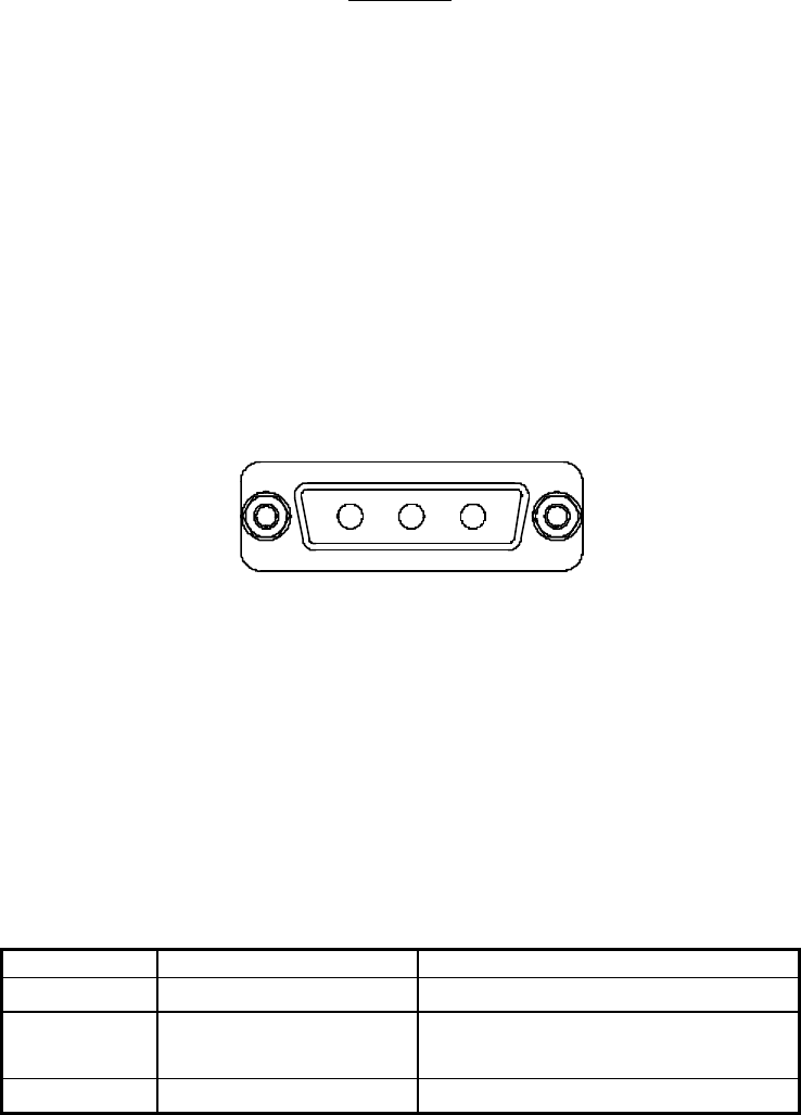
2-5. +26 VDC POWER AND GROUND CONNECTOR P1
The +26 Vdc power and ground connections on the amplifier are made through an 3-pin female D-
Sub connector (figure 2-1) and are listed and described in table 2-1.
321
Figure 2-1. +26 Vdc Power and Ground Connector P1
Table 2-1. +26 Vdc Power and Ground Connector P1 Definition
PIN SIGNAL DESCRIPTION
1+26V +26 Vdc for MCPA
2+26V_RTN +26 Vdc return, grounded to MCPA
chassis ground.
3Chassis Gnd. Chassis Ground
044-05079 Rev. A 2-3
044-05079 Rev. A 2-4
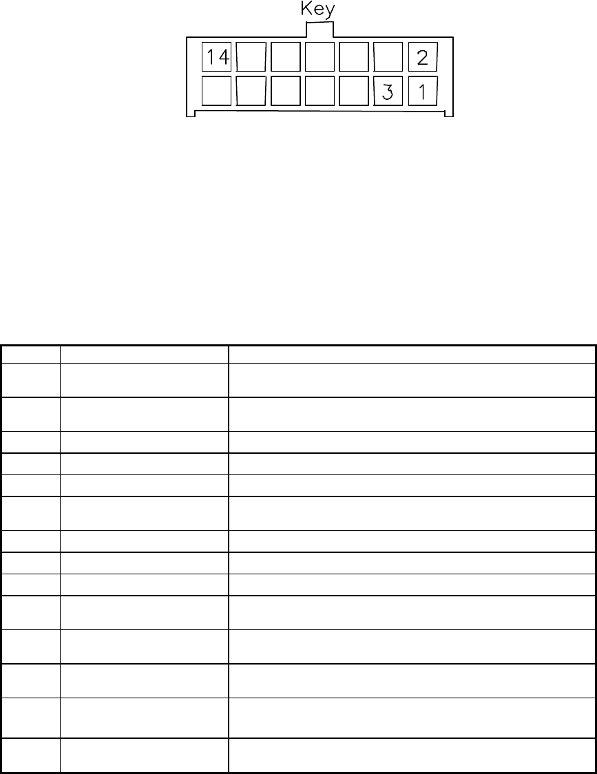
2-6. ALARMS AND SENSING CONNECTOR P2
The alarms and sensing connections on the amplifier are made through a 14-pin micro-fit connector
(figure 2-2) and are listed and described in table 2-2.
Figure 2-2. Alarms and Sensing Connector P2
Table 2-2. Alarms and Sensing Connector P2 Definition
PIN SIGNAL DESCRIPTION
1+5V_AIM 5-volt supply for the AIM; routed directly to the fan
assembly / AIM connector
2+5V_AIM_RTN 5-volt supply return for the AIM; routed directly to the fan
assembly / AIM connector
3+26V_ALARM 26V HPCA alarm input
4+15V_ALARM 15V HPCA alarm input
5REMOTE_SENSE Remote sense for HPCA; connected directly to 26V supply
6REMOTE_SENSE_RTN Remote sense return for HPCA; connected directly to 26V
supply return
7+5V_ALARM 5V HPCA alarm input
8NC Not connected
926ARTN 26V alarm return connected to 26V return on the MCPA
10 ARTN 5V and 15V alarm return connected to 26V return on the
MCPA
11 +26V_FAN 26V supply for the fans; routed to fan assembly / AIM
connector
12 +26V_FAN_RTN 26V supply return for the fans; routed to fan assembly /
AIM connector
13 +26V_FAN 26V supply for the fans; routed to fan assembly /
AIM connector
14 +26V_FAN_RTN 26V supply return for the fans; routed to fan assembly /
AIM connector
044-05079 Rev. A 2-5
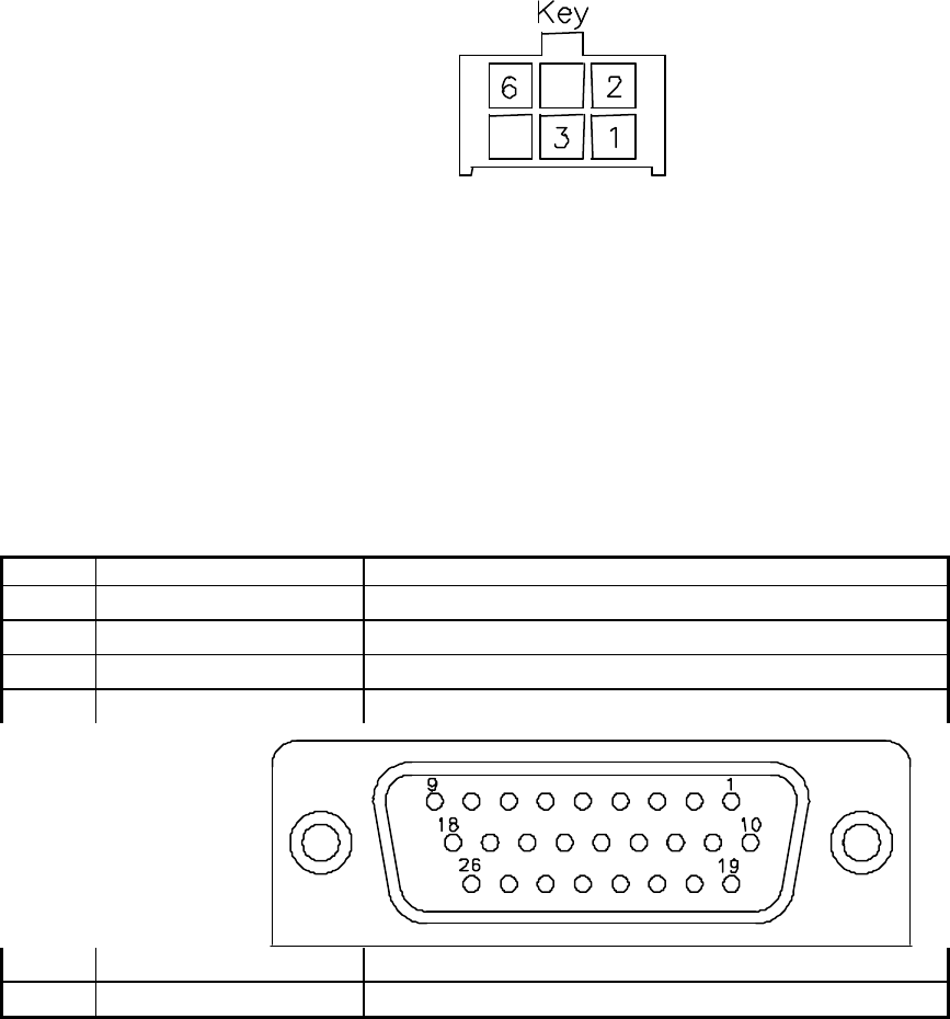
2-7. DIFFERENTIAL IIC CLOCK, RECEIVE, AND TRANSMIT CONNECTOR P3
The alarms and sensing connections on the amplifier are made through a 6-pin micro-fit connector
(figure 2-3) and are listed and described in table 2-3.
Figure 2-3. Differential IIC Clock, Receive, and Transmit Connector P3
Table 2-3. Differential IIC Clock, Receive, and Transmit Connector P3 Definition
PIN SIGNAL DESCRIPTION
1IIC_CLK+ Differential IIC Clock to the DPM
2IIC_CLK- Differential IIC Clock to the DPM
3IIC_RX_DATA+ Differential IIC Receive Data (from DPM)
4IIC_RX_DATA- Differential IIC Receive Data (from DPM)
5IIC_TX_DATA+ Differential IIC Transmit Data (to DPM)
6IIC_TX_DATA- Differential IIC Transmit Data (to DPM)
2-8. IIC, POWER, ALARMS, AND CONTROLS CONNECTOR P4
The alarms and sensing connections on the amplifier are made through a 26-pin high density D-Sub
connector (figure 2-4) and are listed and described in table 2-4.
044-05079 Rev. A 2-6
Figure 2-4. IIC, Power, Alarms, and Controls Connector P4

044-05079 Rev. A 2-7
Table 2-4. IIC, Power, Alarms, and Controls Connector P4 Definition
PIN SIGNAL DESCRIPTION
1+26_FAN 26V supply to the fans; routed from 12-position HPCA
connector
2+26_FAN_RTN 26V supply returnto the fans; routed from 12-position
HPCA connector
3FAN_ALARM1 Alarm for one of three fans in fan assembly / AIM.
Generated by the fan assembly / AIM and sent to the
MFRM via the MCPA’s RS485 link.
4FAN_ALARM2 Alarm for one of three fans in fan assembly / AIM.
Generated by the fan assembly / AIM and sent to the
MFRM via the MCPA’s RS485 link.
5FAN_ALARM3 Alarm for one of three fans in fan assembly / AIM.
Generated by the fan assembly / AIM and sent to the
MFRM via the MCPA’s RS485 link.
6AUX_ALARM+ Analog voltage signal that is generated from either an
external power combiner or an intrusion alarm mechanism,
passed to the MFRM through the RS485.
7AUX_ALARM- Analog voltage signal that is generated from either an
external power combiner or an intrusion alarm mechanism,
passed to the MFRM through the RS485.
8AUX_CTRL1 Contact closure switch on the MCPA but controlled by the
MFRM software. Default status is OPEN upon power up
and CLOSED on power down conditions.
9AUX_CTRL2 Contact closure switch on the MCPA but controlled by the
MFRM software. Default status is OPEN upon power up
and CLOSED on power down conditions.
10 +5V_AIM_RTN 5V supply return for the AIM. Comes from the HPCA via
connector P2 and routed through MCPA.
11 +5V_AIM 5V supply for the AIM. Comes from the HPCA via
connector P2 and routed through MCPA
12 IIC_CLK+ Differential IIC clock to the fan assembly / AIM
13 IIC_CLK- Differential IIC clock to the fan assembly / AIM
14 IIC_RX_DATA+ Differential IIC receive data (from fan assembly / AIM)
15 IIC_RX_DATA- Differential IIC receive data (from fan assembly / AIM)
16 IIC_TX_DATA+ Differential IIC transmit data (to fan assembly / AIM)
17 IIC_TX_DATA- Differential IIC transmit data (to fan assembly / AIM)
18 FORCE_ON+ Routed directly from MTRM connector; turns on LEDs (in
the AIM) during power-up sequence.
19 FORCE_ON- Routed directly from MTRM connector; turns on LEDs (in
the AIM) during power-up sequence.
20 +26V_FAN 26V supply for the fans from (HPCA) connector P2
21 +26V_FAN_RTN 26V supply return for the fans from (HPCA) connector P2
22-26 NC Not connected

044-05079 Rev. A 2-8
2-9. IIC, RS485, POWER, AND OTHER SIGNALS CONNECTOR P5
The alarms and sensing connections on the amplifier are made through a 18-pin micro-fit connector
(figure 2-5) and are listed and described in table 2-5.
Figure 2-5. IIC, RS485, Power, and Other Signals Connector P5
Table 2-5. IIC, RS485, Power, and Other Signals Connector P5 Definition
PIN SIGNAL DESCRIPTION
1FORCE_ON+ Turns on LEDs (in the AIM) during power up sequence;
routed directly from MTRM connector to fan assembly /
AIM connector
2FORCE_ON- Turns on LEDs (in the AIM) during power up sequence;
routed directly from MTRM connector to fan assembly /
AIM connector
3+ALLOW_HPA_ENABLE Enables MCPA when high. Requires enable command via
RS485 and HW_ENABLE high impedance to ground and
no shutdown conditions exist.
4-ALLOW_HPA_ENABLE Enables MCPA when high. Requires enable command via
RS485 and HW_ENABLE high impedance to ground and
no shutdown conditions exist.
5MCPA_TX+ Differential RS485 link to MTRM
6MCPA_TX- Differential RS485 link to MTRM
7MCPA_RX+ Differential RS485 link from MTRM
8MCPA_RX- Differential RS485 link from MTRM
9IIC_CLK+ Differential IIC clock from MTRM
10 IIC_CLK- Differential IIC clock from MTRM
11 IIC_RX_DATA+ Differential IIC receive data (from MTRM)
12 IIC_RX_DATA- Differential IIC receive data (from MTRM)
13 IIC_TX_DATA+ Differential IIC transmit data (to MTRM)
14 IIC_TX_DATA- Differential IIC transmit data (to MTRM)
15 +5V_DC_IN +5V supply voltage for the IIC circuit on MCPA; not used in
any other circuits.
16 +5V_DC_RTN +5V supply voltage return for the IIC circuit on MCPA; not
used in any other circuits.
17 CABLE_DETECT Cable detect line connected to GPI/O port of MTRM

044-05079 Rev. A 2-9
microprocessor. Pulled high via +5V_DC_IN; connected to
reset pin on microcontroller to allow MTRM reset if
necessary.
18 HW_ENABLE Hardware enable signal. MCPA enabled when shorted to
chassis ground.