Powerwave Technologies 5JS0047 Tornado, Model NTGY71AA User Manual 4
Powerwave Technologies Inc Tornado, Model NTGY71AA 4
sect 4

044-05080 Rev. A 4-1
PRINCIPLES OF OPERATION
4-1. INTRODUCTION
This section contains a functional description of the multichannel power amplifier (MCPA).
4-2. RF INPUT SIGNAL
The maximum input power should not exceed the limits specified in table 1-1.
4-3. RF OUTPUT LOAD
The load impedance should be as good as possible (1.5:1 or better) in the working band for good
power transfer to the load.
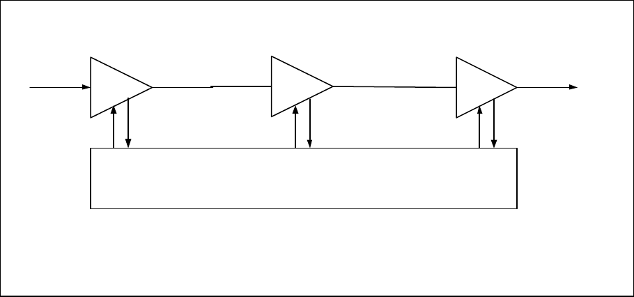
4-4. AMPLIFIER FUNCTIONAL DESCRIPTION
The NTGY71AA amplifier (figures 1-1 and 4-1) is a linear, multichannel power amplifier that operates
in the 25 MHz frequency band from 869 MHz to 894 MHz at an output power of 70 watts. Each
amplifier is a self-contained module and is functionally independent of any other amplifier modules in
the system. Each amplifier module has an alarm board that monitors the amplifier performance. If
a failure or fault occurs in an amplifier module, it is transmitted to the host system via an RS485
interface.
The amplifier is compliant to the requirements of FCC Part 22 with respect to spurious emissions
(see table 1-1). Constant gain is maintained by continuously comparing active paths with passive
references, and correcting for small variations through the RF feedback controls. All gain variations,
for example those due to temperature, are reduced to the passive reference variations. The amplifier
module is comprised of:
An input amplifier
A driver amplifier
A main amplifier
A multifunction board
4-4.1. INPUT AMPLIFIER
RF is fed to the input amplifier, which consists of a bandpass filter, VVAs, and phase shifters for
gain control and phase sweeping functions. They are controlled by a microprocessor on the
multifunction board. At its output, the input amplifier splits the signal to the driver amplifier and
carrier cancellation circuits.
4-4.2. DRIVER AMPLIFIER
The driver amplifier consists of two stages of class AB amplification which provide approximately 40
dB of gain in the 25 MHz frequency band from 869 MHz to 894 MHz. The amplifier operates on +26
Vdc, and a safe bias voltage which is controlled by microprocessors.
Section
4
044-05080 Rev. A 4-2
4-4.3. MAIN AMPLIFIER
The main amplifier employs two class AB amplification stages for maximum efficiency. It provides
approximately 25 dB of gain in the 25 MHz frequency band. The output from the main amplifier is
typically 50.2 dBm. The amplifier operates on +26 Vdc, and gate bias voltages controlled by
microprocessors.
4-4.4. MULTIFUNCTION BOARD
The multifunction board consists of control and alarm circuits. The MCPA communicates to the
host system through the multifunction board which gathers the status information of the amplifier
and reports to the host system via the RS485 interface when instructed. It also protects the MCPA
from adverse conditions such as overpower, input overdrive, overvoltage, etc. A microprocessor on
the multifunction board also controls two loops in the feed-forward system.
4-5. AMPLIFIER MODULE COOLING
Each amplifier module is contained within a thermally conductive chassis which, when properly
mounted on an adequate thermal surface, will provide sufficient cooling to maintain the amplifier
within the specified operating temperature range.
4-6. POWER DISTRIBUTION
Primary DC power for the amplifier is provided by the host system. The amplifier generates all the
required voltages internally from the main source.
RF
IN
INPUT
AMPLIFIER
MAIN
AMPLIFIER
RF
OUT
MULTIFUNCTION BOARD
(ALARMS AND LOOP CONTROLS)
DRIVER
AMPLIFIER
Figure 4-1. NTGY71AA Multichannel Power Amplifier Functional Block Diagram