Powerwave Technologies 5JS0047 Tornado, Model NTGY71AA User Manual 5
Powerwave Technologies Inc Tornado, Model NTGY71AA 5
sect 5
044-05080 Rev. A 5-1
MAINTENANCE
5-1. INTRODUCTION
This section contains periodic maintenance and performance test procedures for the multichannel
power amplifier. It also contains a list of test equipment required to perform the identified tasks.
NOTE
Check your sales order and equipment warranty
before attempting to service or repair the unit. Do not
break the seals on equipment under warranty or the
warranty will be null and void. Do not return
equipment for warranty or repair service until proper
shipping instructions are received from the factory.
5-2. PERIODIC MAINTENANCE
Periodic maintenance requirements are listed in Table 5-1. Table 5-1 also lists the intervals at
which the tasks should be performed.
Table 5-1. Periodic Maintenance
TASK INTERVAL ACTION
Inspection
Cables and Connectors 12 Months Inspect signal and power cables for frayed
insulation. Check RF connectors to be
sure that they are tight.
Performance Tests 12 Months Perform annual test per paragraph 5-5.
5-3. TEST EQUIPMENT REQUIRED FOR TEST
Test equipment required to test the amplifier is listed in Table 5-2. Equivalent test equipment may
be substituted for any item, keeping in mind that a thermistor type power meter is required.
NOTE
All RF test equipment must be calibrated to 0.05
dB resolution. Any deviation from the nominal
attenuation must be accounted for and factored
into all output readings.
Section
5

044-05080 Rev. A 5-2
Table 5-2. Test Equipment Required
MENCLATURE MANUFACTURER MODEL
Signal Generator Agilent (H.P.) ESG4433B
30 dB Attenuator, 250 Watt Tenuline
Spectrum Analyzer H.P. 8562E
Coax Directional Coupler H.P. 778D
Power Meter / Sensor H.P. 437B / 8481A
Network Analyzer H.P. 8753D
Current Probe
Source Diskette Powerwave
5-4. PERFORMANCE TEST
Performance testing should be conducted every 12 months to ensure that the amplifier system
meets the operational specifications listed in table 5-3. Also verify system performance after any
amplifier module is replaced in the field. The test equipment required to perform the testing is listed
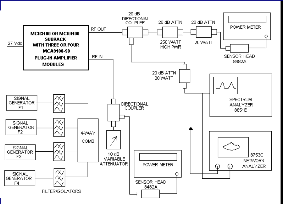
in table 5-2, and the test setup is shown in figure 5-1.
5-4.1. AMPLIFIER PERFORMANCE TEST.
To perform the test, proceed as follows:
1. Connect test equipment as shown in figure 5-1.
NOTE
Do not apply any RF signals at this time.
AMPLIFIER SPURIOUS EMISSIONS TEST:
2. Load the MFRM waveform on the ESG (signal generator). Apply this signal through a driver
amplifier to the MCPA so that the RF signal going into the MCPA is approximately -1.5
dBm (adjust the input RF signal level to get 48.5 dBm output power). Measure spurious
emissions. Verify that it is within specification.
GAIN TEST:
3. Set input power level to power amplifier at –1.5 dBm (869, 881, and 894 MHz).
4. Measure the output power in dBm.
5. Subtract input power (in dBm) from output power (in dBm) to get gain.
6. Check the amplifier gain across the band from 869 MHz to 894 MHz. Gain should be 50 ±2
dB. Record test data in table 5-3.
INPUT RETURN LOSS TEST:
7. Read and record the S11 return loss measurement on network analyzer. Record test data in
table 5-3.
044-05080 Rev. A 5-3
Figure 5-1. NTGY71AA Amplifier Test Setup Diagram

044-05080 Rev. A 5-4
Table 5-3. Multichannel Power Amplifier NTGY71AA Test Data Sheet
Tested By: ______________________ Serial No: ____________________
Pass/Fail: ______________________ Date: ________________________
70W MCPA Test
Test Conditions: Load and source impedance: 50 ohms, VSWR < 1.2:1
Supply voltage: (+26) Vdc ±± 0.1 Vdc (unless otherwise noted).
Network Analyzer Span: 25 MHz
Marker #1 = 869 MHz, #2 = 881 MHz, #3 = 894 MHz
TEST CONDITION MIN MAX FREQUENCY (MHz)
1.00 NETWORK ANALYZER 869 881 894
1.01 Gain 49.5dB 50.5dB
1.02 Gain Flatness 0 dB ±0.2 dB/
1.25 MHz
1.03 Input Return Loss, worst case In band -14 dB
1.04 Output Return Loss, worst case In band -14 dB
2.00 CDMA TESTS
3 CDMA TONES: @ 70W out
•Spec. Ana. With 10 MHz Res. BW
2.01 ∆∆@ +1.5MHz -61 dBc
2.02 ∆∆@ –1.5MHz -61 dBc
2.03 Current @ 70 W (48.5 dBm) out 23.4A
3.00 RMS Power Detection
3.01 RMS reading in Watts @ Pout = 48.5 dBm -0.5dB +0.5dB
3.02 RMS reading in Watts @ Pout = 43.5 dBm -0.5dB +0.5dB
4.00 ALARM TESTS
4.01 Excessive DC Voltage (>27 V) Check
4.02 Verify Over Power Alarm
(>51 dBm for >3 sec) Check
4.03 FWD PWR Voltage (4.26V @ 48.5 dBm) Check
4.04 REV PWR Voltage (4.26V @ 48.5 dBm) Check
5.00 FIRMWARE VERSION 2.05
044-05080 Rev. A 5-5
5-5. FIELD REPLACEMENT OF THE MODULE
The NTGY71AA multichannel power amplifier module can be replaced in the field on site by a
qualified technician with experience maintaining RF power amplifiers and similar equipment.
To replace a power amplifier module, proceed as follows:
1. Turn off 26 Vdc power to that specific module.
2. Disconnect the two RF cables and connectors P1 through P5.
3. Remove 13 screws that secure amplifier module to heat sink.
4. Carefully remove amplifier module from heat sink.
5. Add Thermstrate thermal interface pad to surface of replacement amplifier
which mates with heatsink.
6. Install replacement in reverse order of steps 1 through 4 above.