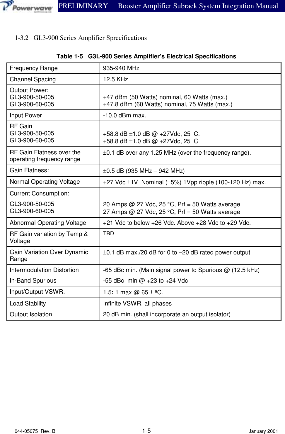
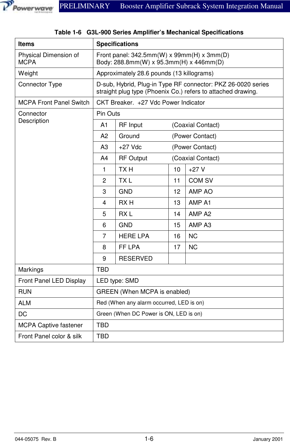
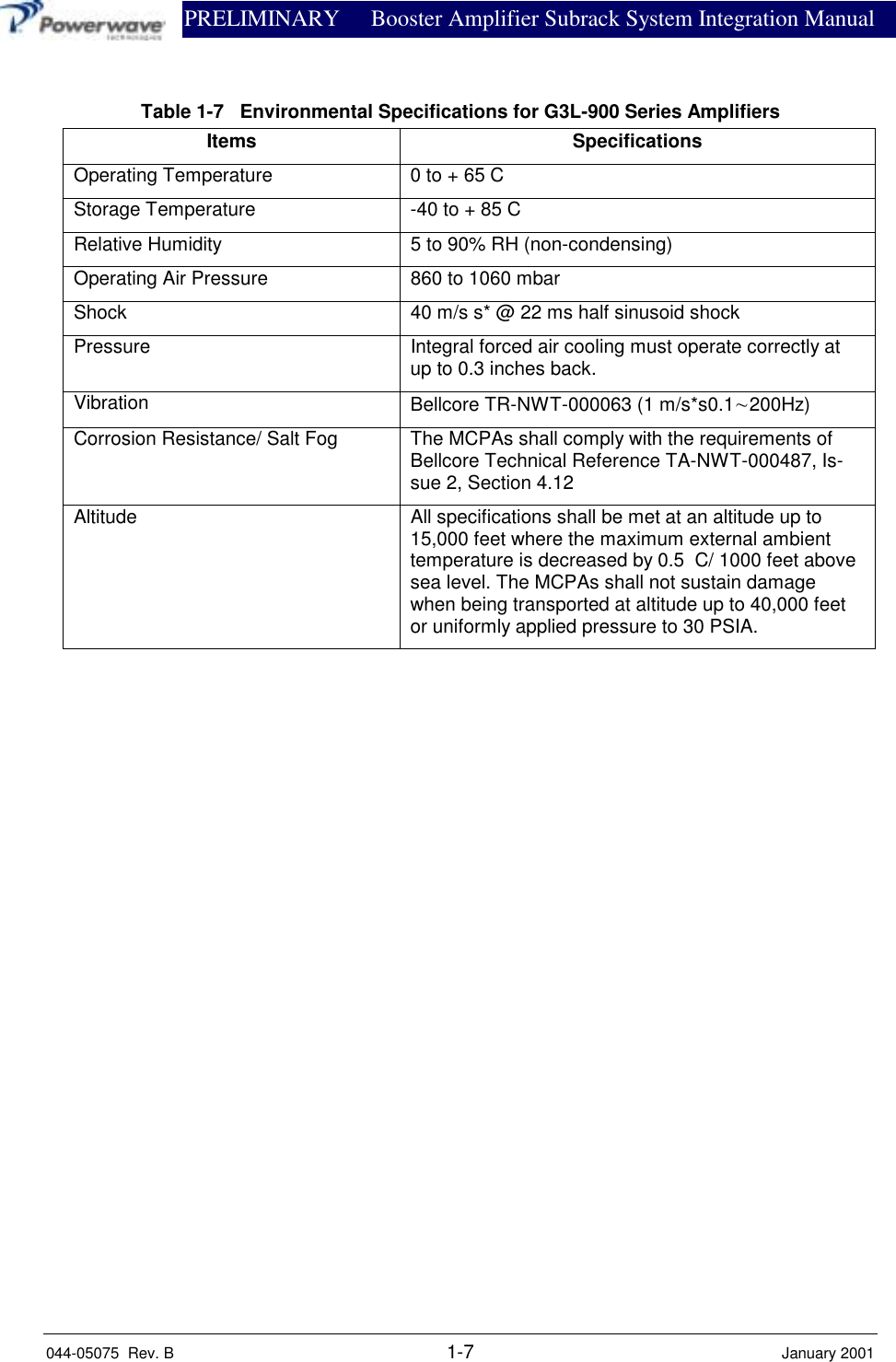
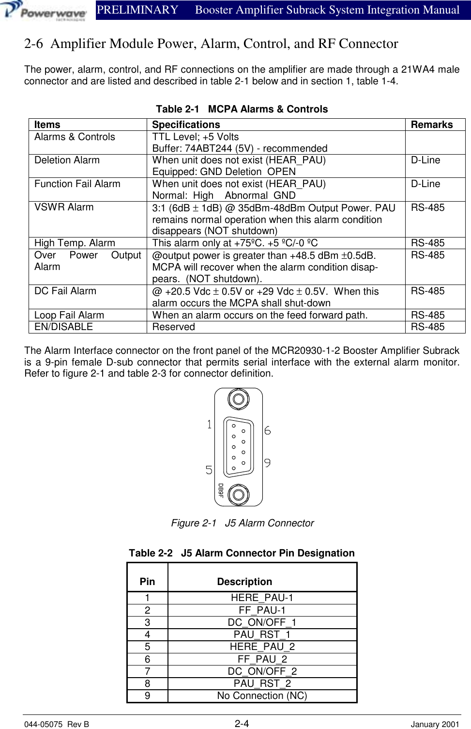
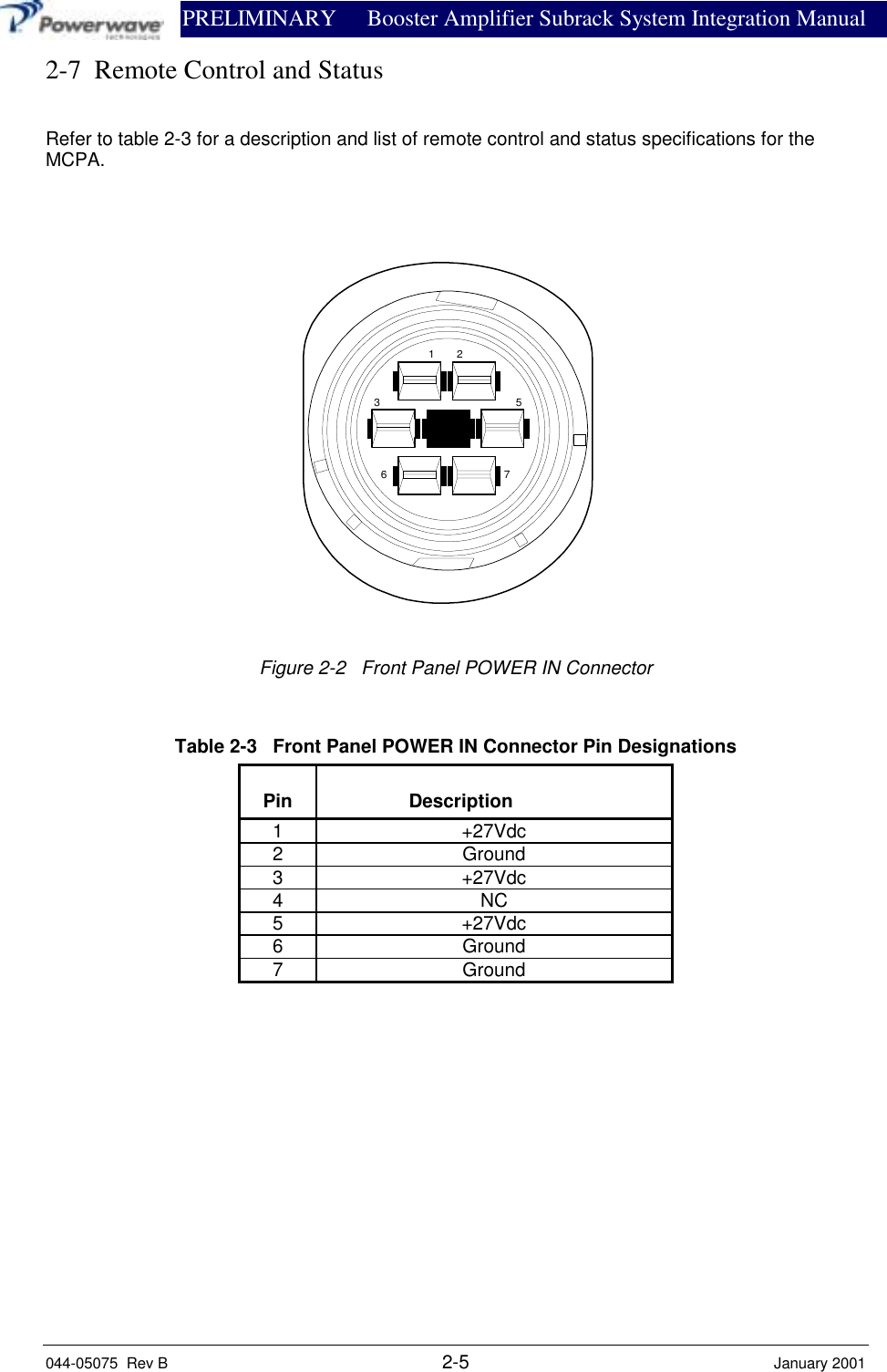
Powerwave Technologies 5JS0052 G3L-900-60-005 User Manual I GENERAL DESCRIPTION

Powerwave Technologies Inc G3L-900-60-005 I GENERAL DESCRIPTION

user manual

               PRELIMINARY 935-940 MHz044-05075  Rev. B January 2001System Integration Manual
                            PRELIMINARY     Booster Amplifier Subrack System IntegrationManual044-05075  Rev. B January 2001iiiTable Of ContentsPar. Section 1 PageNo. General Description No.1-1 Introduction....................................................................................................................................1-11-2 General  Description ......................................................................................................................1-11-3 Functional And Physical Specifications .........................................................................................1-21-3.1 MCR20930-1-2 Subrack Specifications.........................................................................................1-31-3.2 GL3-900 Series Amplifier Specifications ......................................................................................1-51-4 Booster Amplifier Subrack Major Components.............................................................................1-81-5 Equipment Changes........................................................................................................................1-8Section 2Installation2-1 Introduction....................................................................................................................................2-12-2 Site Survey.....................................................................................................................................2-12-3 Electrical Service Recommendations.............................................................................................2-12-4 Air Conditioning ............................................................................................................................2-12-5 Unpacking and Inspection..............................................................................................................2-22-6 Installation Instructions..................................................................................................................2-32-7 Amplifier Module Power, Alarm, Control, and RF Connector ......................................................2-42-8 Remote Control and Status.............................................................................................................2-5Section 3Operating Instructions3-1 Introduction....................................................................................................................................3-13-2 Initial Start-Up and Operating Procedures.....................................................................................3-1Section 4Principles of Operation4-1 Introduction....................................................................................................................................4-14-2 RF Input Signal ..............................................................................................................................4-14-3 RF Output Load .............................................................................................................................4-14-4 System Functional Description.......................................................................................................4-14-5 Multi-Carrier Power Amplfier Functional Description ..................................................................4-24-5.1 Predriver Amplifier ........................................................................................................................4-34-5.2 Three Stage Driver Amplifier.........................................................................................................4-34-5.3 Main Amplifier...............................................................................................................................4-34-5.4 Alarm Monitoring and Control.......................................................................................................4-34-5.5 Loop Control Circuit......................................................................................................................4-34-6 Amplifier Module Cooling.............................................................................................................4-44-7 Power Distribution.........................................................................................................................4-4
                            PRELIMINARY     Booster Amplifier Subrack System IntegrationManual044-05075  Rev. B January 2001ivTable Of Contents (Continued)Par. Section 5 PageNo. Maintenance No.5-1 Introduction....................................................................................................................................5-15-2 Periodic Maintenance.....................................................................................................................5-15-3 Test Equipment Required For Test ................................................................................................5-15-4 Performance Test ...........................................................................................................................5-25-4.1 Amplifier Performance Test...........................................................................................................5-25-4.1.1 Amplifier Spurious Emissions Test................................................................................................5-25-4.1.2 Gain Test........................................................................................................................................5-25-4.1.3 Input Return Loss...........................................................................................................................5-25-5 Field Replacement of the Module ..................................................................................................5-5Section 6Troubleshooting6-1 Introduction....................................................................................................................................6-16-2 Troubleshooting .............................................................................................................................6-16-3 Return for Service Procedures........................................................................................................6-16-3.1 Obtaining an RMA.........................................................................................................................6-16-3.2 Repackaging for Shipment.............................................................................................................6-1List Of AppendicesPageAppendix No.A Booster Amplifier Subrack Backplane Wiring Diagram...............................................................A-1B Disrtibution Printed Circuit Board Pinout Location......................................................................B-1C Power Setting Procedure...............................................................................................................C-1List Of IllustrationsFigure PageNo. No.1-1 VVA, Voltage Regulator and Dip Switch Pin Configuration.........................................................1-21-2 Booster Amplifier Subrack System-Top View...............................................................................1-91-3 Booster Amplifier Subrack Sysytem-Front View.........................................................................1-101-4 Booster Amplifier Subrack System-Side View (Front Door Open) .............................................1-111-5 Booster Amplifier Subrack System-Side View with Fans Removed............................................1-111-6 Booster Amplifier Subrack-Backplane.........................................................................................1-121-7 GL3-900 Series Amplifier............................................................................................................1-131-8 GL3-900 Series Amplifier – Rear, Top, Front Views ..................................................................1-14Table Of Contents (Continued)
                            PRELIMINARY     Booster Amplifier Subrack System IntegrationManual044-05075  Rev. B January 2001vList Of Illustrations (Continued)2-1 J5 Alarm Connector .......................................................................................................................2-42-7 Front Panel POWER IN Connector ...............................................................................................2-54-1 System Block Diagram...................................................................................................................4-14-2 G3L-900-50/60-005 Multi-Carrier Power Amplifier Functional Block Diagram ..........................4-25-1 G3L-900-50/60-005 Amplifier Test Setup Diagram......................................................................5-3List Of TablesTable PageNo. No.1-1 Truth Table (Variable Attenuator) .................................................................................................1-21-2 Booster Amplifier Subrack System Specifications.........................................................................1-31-3 2-Way Splitter Electrical Specifications ........................................................................................1-41-4 2-Way Combiner Specifications.....................................................................................................1-41-5 G3L-900-Series Ampifier Electrical Specifications.......................................................................1-51-4 G3L-900-Series Amplifier Mechnaical Specifications...................................................................1-61-7 GL3-900 Series Amplifier Environmental Specifications..............................................................1-71-8 Major BAR System Components...................................................................................................1-82-1 Remote Control and Status Specifications .....................................................................................2-52-2 J5 Alarm Connector Pin Designation.............................................................................................2-42-3 Front Panel POWER IN Connector Pin Designations....................................................................2-55-1 Periodic Maintenance.....................................................................................................................5-15-2 Test Equipment Required...............................................................................................................5-15-3 Multichannel Power Amplifier Test Data Sheet.............................................................................5-46-1 Troubleshooting .............................................................................................................................6-1
               PRELIMINARY Booster Amplifier Subrack System Integration Manual044-05075  Rev. B 1-1 January 2001Section 1.  General Description1-1  IntroductionThis manual contains information and procedures for the installation, operation, and maintenanceof Powerwave Technologies, Inc.’s (Powerwave’s) Booster Amplifier Subrack (BAS) system.  Thismanual is organized into the following sections:Section 1. General Description Appendix A: Backplane Wiring DiagramSection 2. Installation Appendix B: Distribution PCB Pinout LocationSection 3. Operating Instructions Appendix C: Power Setting ProcedureSection 4. Principles of OperationSection 5. MaintenanceSection 6: Troubleshooting1-2  General DescriptionEngineered to operate in a 2-way transceiver paging base station, the BAS system is a linear,Multi-Carrier Power Amplifier (MCPA) system that operates in the 5 MHz frequency band from935 MHz to 940 MHz.  The system integrates the model MCR20930-1-2 Booster AmplifierSubrack (BAS) with two model G3L-900-50-005 MCPAs to deliver a composite RF output of75.8 Watts (nominal), after combined losses.  The system can also integrate two model G3L-900-60-005 MCPAs to deliver a composite RF output of 91 Watts (nominal), after combined losses.Designed to function as a subrack (see Figures 1-2 thru 1-6) in the host base station, the enclo-sure has a one inch (right and left side) flanged front panel and eight mounting holes (four oneach side) to secure the Subrack into place (refer to Figure 1-3 for mounting hole locations).  Toaid in maintaining the system’s operating temperature, the BAS is equipped with two cooling fansmounted on the front access door (see Figures 1-3 and 1-4).  The G3L-900-50-005 amplifier dis-places 1,672 BTUs of heat at full power.  The G3L-900-60-005 amplifier displaces approximately1,900 BTUs of heat at full power.The composite input signal is applied to a 30dB 10W input attenuator, followed by a voltage vari-able attenuator that is controlled via dip switches on the front panel (refer to table 1-1 and figure4-1).  The maximum composite input signal may not exceed +31dBm.  The composite signal isthen fed to a two-way power splitter.  The signals are applied to the amplifiers, and the amplifieroutputs are combined again (refer to Tables 1-2 through 1-7 for specifications).  With both ampli-fiers installed, the system provides 20dB of gain.The BAS also houses a distribution printed circuit board (PCB) for internal power and alarm distri-bution (refer to Appendix B).  Accessible from the front panel is the DB9 external ALARM con-nector, the RF IN and RF OUT type N connectors.Additionally, the front panel provides access to the +27 Vdc POWER IN connector, visibility of thetwo MCPA’s fault alarm LED indicators and the GAIN CTRL dip switch.  Refer to table 1-1 for thedip switch truth table and fiqure 1-1 for pin designations.With the access door open, the two amplifier modules are visible.  All solid-state, the MCPAs aredesigned for parallel operation for high peak power output.  Their modular construction andunique and highly effective LED-based operational status and fault indicators help minimizedowntime.  The turn-on and turn-off sequence of voltages are fully automatic, as is overload pro-tection and recycling.  Inadvertent operator damage from front panel manipulation is virtually im-possible.  Refer to Figures 1-7 and 1-8 for drawing views of the amplifier module.
               PRELIMINARY Booster Amplifier Subrack System Integration Manual044-05075  Rev. B 1-2 January 2001Table 1-1   Truth Table Input Variable AttenuatorPin 1 Pin 2 Pin 3 Pin 4 Attenuation+5Vdc +5Vdc +5Vdc +5Vdc 0dB+5Vdc +5Vdc +5Vdc 0Vdc 1dB+5Vdc +5Vdc 0Vdc +5Vdc 2dB+5Vdc +0Vdc +5Vdc +5Vdc 4dB+5Vdc +5Vdc +5Vdc 0Vdc 8dB0Vdc 0Vdc 0Vdc 0Vdc 15dB123456781234512345678910+5Vdc OUTPUTGNDGNDGNDGNDINPUTVoutGNDGNDNCNCGNDGND+27Vdc (Vin)VOLTAGEREGULATORDIP SWITCHSOCKET VARIABLEATTENUATORFigure 1-1   Variable Attenuator, Voltage Regulator and Dip Switch Socket Pin Configuration1-3  Functional and Physical SpecificationsThe BAS system’s functional and physical specifications are listed in table 1-2.  A functional blockdiagram is provided in section 4 of this manual to illustrate the system’s operational layout.
               PRELIMINARY Booster Amplifier Subrack System Integration Manual044-05075  Rev. B 1-3 January 20011-3.1   MCR20930-1-2 Subrack SpecificationsTable 1-2   MCR20930-1-2 Booster Amplifier Subrack System SpecificationsFrequency 935-940 MHzGain +20 dBm, ± 0.2 dBmRF Input Power +31 dBm composite w/variable attenuator set to 0dB at-tenuation.+46 dBm composite w/variable attenuator set to 15 dB at-tenuation.RF Output Power:G3L-900-50-005G3L-900-60-00543.5 Watts (+46.39 dBm) nominal, 1 module75.8 Watts (+48.80 dBm) nominal, 100 W (max.), 2 modules52.3 Watts (+47.18 dBm) nominal, 1 module91.0 Watts (+49.59 dBm) nominal, 120 W (max.), 2 modulesPhase Variation ± 5°Alarms +5 Vdc TTLD.C. Power + 27 Vdc, 55 Amps maxTotal System Return Loss -19 dBmChannel Spacing 12.5 KHzOperating Temperature 0 to 65 degrees CSubrack Dimensions 12.22(H)x*17(W)x24.5(D) inchesWeight (Fully assembled) Approximately 80 Pounds (36.28 kilograms)*Note: Does not include 1-inch right and left side mounting flanges.
               PRELIMINARY Booster Amplifier Subrack System Integration Manual044-05075  Rev. B 1-4 January 2001Table 1-3   Electrical Specifications for 2-Way SplitterInsertion Loss -33dB Min. (TBD on actual part)-48dB Max.Amplitude Balance ±0.2dB Max.Insertion Loss Flatness Over Frequency ±0.3dB Max.Input/Output Return Loss -20dB Min.Port to Port Phase Delta ±5 Degrees Max.Port to Port Isolation -20.0dB Min.IP3 (Input Power = 5dBm) -90dBc Min.Power Handling (Fixed Attenuator) 20 Watts Max.Power Handling (Variable Attenuator) 3.16 Milliwatts Max.Table 1-4   Electrical Specifications for 2-Way CombinerInsertion Loss -0.6 dB (TBD on actual parts)Amplitude Balance ±0.2dB Max.Insertion Loss Flatness Over Frequency ±0.3dB Max.Input/Output Coupled Port Return Loss -18.0 dB Min.Port to Port Phase Delta ±5 Degrees Max.Port to Port Isolation -20.0dB Min..Power Handling 120 WattsSampling Coupler -25dB ±1dBSampling Coupler Directivity -18.0 dB Min.IP3 (Input Power = TBD) -100 dBc Min
               PRELIMINARY Booster Amplifier Subrack System Integration Manual044-05075  Rev. B 1-5 January 20011-3.2   GL3-900 Series Amplifier SprecificationsTable 1-5   G3L-900 Series Amplifier’s Electrical SpecificationsFrequency Range 935-940 MHzChannel Spacing 12.5 KHzOutput Power:GL3-900-50-005GL3-900-60-005 +47 dBm (50 Watts) nominal, 60 Watts (max.)+47.8 dBm (60 Watts) nominal, 75 Watts (max.)Input Power -10.0 dBm max.RF GainGL3-900-50-005GL3-900-60-005 +58.8 dB ±1.0 dB @ +27Vdc, 25  C.+58.8 dB ±1.0 dB @ +27Vdc, 25  CRF Gain Flatness over theoperating frequency range ±0.1 dB over any 1.25 MHz (over the frequency range).Gain Flatness: ±0.5 dB (935 MHz – 942 MHz)Normal Operating Voltage +27 Vdc ±1V  Nominal (±5%) 1Vpp ripple (100-120 Hz) max.Current Consumption:GL3-900-50-005GL3-900-60-005 20 Amps @ 27 Vdc, 25 °C, Prf = 50 Watts average27 Amps @ 27 Vdc, 25 °C, Prf = 50 Watts averageAbnormal Operating Voltage +21 Vdc to below +26 Vdc. Above +28 Vdc to +29 Vdc.RF Gain variation by Temp &VoltageTBDGain Variation Over DynamicRange ±0.1 dB max./20 dB for 0 to –20 dB rated power outputIntermodulation DistortionIn-Band Spurious-65 dBc min. (Main signal power to Spurious @ (12.5 kHz)-55 dBc  min @ +23 to +24 VdcInput/Output VSWR. 1.5: 1 max @ 65 ± ºC.Load Stability Infinite VSWR. all phasesOutput Isolation 20 dB min. (shall incorporate an output isolator)
               PRELIMINARY Booster Amplifier Subrack System Integration Manual044-05075  Rev. B 1-6 January 2001Table 1-6   G3L-900 Series Amplifier’s Mechanical SpecificationsItems SpecificationsPhysical Dimension ofMCPA Front panel: 342.5mm(W) x 99mm(H) x 3mm(D)Body: 288.8mm(W) x 95.3mm(H) x 446mm(D)Weight Approximately 28.6 pounds (13 killograms)Connector Type D-sub, Hybrid, Plug-in Type RF connector: PKZ 26-0020 seriesstraight plug type (Phoenix Co.) refers to attached drawing.MCPA Front Panel Switch CKT Breaker.  +27 Vdc Power IndicatorPin OutsA1 RF Input (Coaxial Contact)A2 Ground (Power Contact)A3 +27 Vdc (Power Contact)A4 RF Output (Coaxial Contact)1 TX H 10 +27 V2TX L 11COM SV3 GND 12 AMP AO4RX H 13AMP A15RX L 14AMP A26 GND 15 AMP A37 HERE LPA 16 NC8 FF LPA 17 NCConnectorDescription9 RESERVEDMarkings TBDFront Panel LED Display LED type: SMDRUN GREEN (When MCPA is enabled)ALM Red (When any alarm occurred, LED is on)DC Green (When DC Power is ON, LED is on)MCPA Captive fastener TBDFront Panel color & silk TBD
               PRELIMINARY Booster Amplifier Subrack System Integration Manual044-05075  Rev. B 1-7 January 2001Table 1-7   Environmental Specifications for G3L-900 Series AmplifiersItems SpecificationsOperating Temperature 0 to + 65 CStorage Temperature -40 to + 85 CRelative Humidity 5 to 90% RH (non-condensing)Operating Air Pressure 860 to 1060 mbarShock 40 m/s s* @ 22 ms half sinusoid shockPressure Integral forced air cooling must operate correctly atup to 0.3 inches back.Vibration Bellcore TR-NWT-000063 (1 m/s*s0.1∼200Hz)Corrosion Resistance/ Salt Fog The MCPAs shall comply with the requirements ofBellcore Technical Reference TA-NWT-000487, Is-sue 2, Section 4.12Altitude All specifications shall be met at an altitude up to15,000 feet where the maximum external ambienttemperature is decreased by 0.5  C/ 1000 feet abovesea level. The MCPAs shall not sustain damagewhen being transported at altitude up to 40,000 feetor uniformly applied pressure to 30 PSIA.
               PRELIMINARY Booster Amplifier Subrack System Integration Manual044-05075  Rev. B 1-8 January 20011-4  Booster Amplifier Subrack (BAS) System Major ComponentsTable 1-8 lists the model numbers and descriptions of the major components that comprise theBAS system and the document number (if available) of the manual related to each component.Table 1-8   Major BAS System ComponentsModel/PN Description Qty PerSystemExpandableTo800-01292-001 Top Assembly, BAS II w/oCombiner Backplane 11800-01294-001 Front Panel Assy 1 1700-00901-001 Cable Assy, Power In 1 1700-00902-001 Cable Assy, Amp Power 1 1700-00903-001 Cable Assy, Amp Power 1 1700-00904-001 Cable Assy, Fan 2 2700-00905-001 Cable Assy, Amplifier 1 1800-001296-001 Fan Assy 2 2800-01297-001 Tray Assy 1 1500-01425-001 PCB Assy, Power Distribution 1 1MCR20930-1-2 Booster Amplifier Subrack 1 1GL3-900-50-005 orGL3-900-60-005 50-Watt Amplifier60-Watt Amplifier 22221-5  Equipment ChangesPowerwave Technologies, Inc. reserves the right to make minor changes to the equipment, in-cluding but not limited to component substitution and circuitry changes.  Changes that impact thismanual may be incorporated in a later revision of the manual.
               PRELIMINARY Booster Amplifier Subrack System Integration Manual044-05075  Rev. B 1-9 January 2001Figure 1-2   Booster Amplifier Subrack System – Top View
               PRELIMINARY Booster Amplifier Subrack System Integration Manual044-05075  Rev. B 1-10 January 2001
               PRELIMINARY Booster Amplifier Subrack System Integration Manual044-05075  Rev B 2-1 January 2001Section 2.  Installation2-1  IntroductionThis section contains unpacking, inspection, installation instructions and recommendations for theBooster Amplifier Subrack (BAS) System.  It is important that the licensee perform the followingtasks correctly and in good faith:1.  Carefully read all material in this section prior to equipment unpacking or installation.2.  Also, read and review the operating procedures in section 3 prior to installing the equipment.3.  If applicable, carefully review the Federal Communications Commission (FCC) rules as theyapply to your installation.  DON'T TAKE CHANCES WITH YOUR LICENSE.2-2  Site SurveyPowerwave Technologies recommends that site surveys be performed by qualified individuals orfirms prior to equipment ordering or installation.  Performing a detailed site survey will reduce oreliminate installation and turn-up delays caused by oversights.  Pay particular attention to powerplant capacity, air conditioning needs, and RF/DC cabling/breaker requirements.2-3  Electrical Service RecommendationsPowerwave recommends that:!  Proper AC line conditioning and surge suppression be provided on the primary AC input to the+27 Vdc power source.!  All electrical service should be installed in accordance with the National Electrical Code, anyapplicable state or local codes, and good engineering practice.!  Straight, short ground runs be used.!  The electrical service must be well grounded.Circuit breakers should be thermal type, capable of handling the anticipated inrush current, in aload center with a master switch.2-4  Air ConditioningEach GL3-900-50-005 and GL3-900-60-005 amplifier generates 1672 BTUs and 1900 BTUs ofheat respectively at full power.  A fully populated MCR20930-1-2 Booster Amplifier Subrack sys-tem operating at full power will generate 3344 BTU's of heat (using two GL3-900-50-005 amplifi-ers) and 3800 BTUs (using two GL3-900-60-005) amplifiers.  At least a 1/3-ton air conditioner isneeded to cool this Powerwave equipment.
               PRELIMINARY Booster Amplifier Subrack System Integration Manual044-05075  Rev B 2-2 January 2001Unpacking and InspectionThis equipment (as applicable) has been operated, tested and calibrated at the factory.  Carefullyopen and remove the MCPAs and model MCR20930-1-2 Booster Amplifier Subrack (BAS) fromtheir respective containers.  Retain all packing material that can be reassembled in the event thatthe unit must be returned to the factory.  Please perform the following steps:CAUTIONExercise care in handling equipment during inspection to prevent damage caused byrough or careless handling.1.  Visually inspect the MCPAs and the BAS for damage that may have occurred during ship-ment.2.  Check for evidence of water damage, bent or warped chassis, loose screws or nuts, or extra-neous packing material in the connector(s).CAUTIONBefore applying power, make sure that all connectors to the BAS components aresecure.  Make sure that the input and output of the BAS are properly terminated at 50ohms.  Do not operate the system without a load attached.  Refer to section 1, table 1-2 for input power requirements.  Excessive input power may damage the equipment.If possible, inspect the equipment in the presence of the delivery person.If the equipment is damaged:!  The carrier is your first area of recourse.!  A claim should be filed with the carrier once the extent of any damage is assessed.  We can-not stress too strongly the importance of IMMEDIATE careful inspection of the equipment andthe subsequent IMMEDIATE filing of the necessary claims against the carrier if necessary.If the equipment is damaged and must be returned to the factory:!  Please write or phone for return authorization.  Refer to section 6-3.1 of this manual for in-structions.!  Powerwave may not accept returns without a return authorization.Claims for loss or damage may not be withheld from any payment to Powerwave nor may anypayment due be withheld pending the outcome thereof.  WE CANNOT GUARANTEE THEFREIGHT CARRIER'S PERFORMANCE
               PRELIMINARY Booster Amplifier Subrack System Integration Manual044-05075  Rev B 2-3 January 20012-5  Installation InstructionsThe model MCR20930-1-2 Booster Amplifier Subrack (BAS) is designed for use in a2-way transceiver paging base station.  The host enclosure must permit access to the subrack for;DC power, RF and monitor cables.  As well as, proper ventilation.  The BAS system is designedfor an enclosure with at least 36 inches of depth.  Please proceed with installation as follows:WARNINGVerify that all circuit breaker switches on the subrack are in the OFF position.  Turnoff external primary DC power before connecting DC power cables.1.  Install the subrack into the host base station and secure it into place using #10 32x1/2 Phil-lips screws and #10 flat washers.2.  Connect POWER IN (+27 Vdc) to the subrack.  Refer to figure 2-1 for pin locations and Ta-ble 2-2 for pin designations.3.  Connect RF IN cable to the subrack.4.  Connect RF OUT cable to the subrack.5.  Connect external ALARM interface to external summary board.  Refer to figure 2-2 for pinlocations and table 2-4 for pin designation.6.  Loosen thumbscrews to the front access door and open the door.7.  Before installing the MPCA into the subrack, inspect the 21-pin D-sub male combo connectoron the rear of each amplifier.  Verify that all pins are straight, no pins are recessed, and thatthe alignment shield is not bent.8.  Place power ON/OFF switch on the MCPA’s front panel in the “off” (far-left) position.WARNINGDo not slam amplifiers into the subrack.  Forcing the amplifier into the surack at toofast a rate may cause the pins on the 21-D-sub conector of the amplifier to becomerecessed or broken.9.  Insert a plug-in MCPA into the subrack.  Tighten thumbscrews.10.  Repeat steps 7, 8 and 9 for the second MCPA.WARNINGCheck your work before applying DC voltage to the system.  Make certain allconnections are tight and correct.11. Measure primary DC input voltage.  DC input voltage should be +27 Vdc ±1.0 Vdc.  If the DCinput voltage is above or below the limits, call and consult Powerwave before you turn on youramplifier system.12. Refer to section 3 for initial turn-on and checkout procedures.
               PRELIMINARY Booster Amplifier Subrack System Integration Manual044-05075  Rev B 2-4 January 20012-6  Amplifier Module Power, Alarm, Control, and RF ConnectorThe power, alarm, control, and RF connections on the amplifier are made through a 21WA4 maleconnector and are listed and described in table 2-1 below and in section 1, table 1-4.Table 2-1   MCPA Alarms & ControlsItems Specifications RemarksAlarms & Controls TTL Level; +5 VoltsBuffer: 74ABT244 (5V) - recommendedDeletion Alarm When unit does not exist (HEAR_PAU)Equipped: GND Deletion  OPEN D-LineFunction Fail Alarm When unit does not exist (HEAR_PAU)Normal:  High    Abnormal  GND D-LineVSWR Alarm 3:1 (6dB ± 1dB) @ 35dBm-48dBm Output Power. PAUremains normal operation when this alarm conditiondisappears (NOT shutdown)RS-485High Temp. Alarm This alarm only at +75ºC. +5  ºC//-0  ºC RS-485Over Power OutputAlarm @output power is greater than +48.5 dBm ±0.5dB.MCPA will recover when the alarm condition disap-pears.  (NOT shutdown).RS-485DC Fail Alarm @ +20.5 Vdc ± 0.5V or +29 Vdc ± 0.5V.  When thisalarm occurs the MCPA shall shut-down RS-485Loop Fail Alarm When an alarm occurs on the feed forward path. RS-485EN/DISABLE Reserved RS-485The Alarm Interface connector on the front panel of the MCR20930-1-2 Booster Amplifier Subrackis a 9-pin female D-sub connector that permits serial interface with the external alarm monitor.Refer to figure 2-1 and table 2-3 for connector definition.Figure 2-1   J5 Alarm ConnectorTable 2-2   J5 Alarm Connector Pin DesignationPin Description1 HERE_PAU-12 FF_PAU-13 DC_ON/OFF_14 PAU_RST_15 HERE_PAU_26 FF_PAU_27 DC_ON/OFF_28 PAU_RST_29 No Connection (NC)
               PRELIMINARY Booster Amplifier Subrack System Integration Manual044-05075  Rev B 2-5 January 20012-7  Remote Control and StatusRefer to table 2-3 for a description and list of remote control and status specifications for theMCPA.Figure 2-2   Front Panel POWER IN ConnectorTable 2-3   Front Panel POWER IN Connector Pin DesignationsPin Description1 +27Vdc2 Ground3 +27Vdc4NC5 +27Vdc6 Ground7 Ground235671
               PRELIMINARY Booster Amplifier Subrack System Integration Manual044-05075  Rev B 2-6 January 2001Table 2-4   Remote Control and StatusItems SpecifcationsRS-485PhysicalLayerEach MCPA shall support an RS-485 multi-drop differential serial asynchro-nous communications link operation at 9600 baud, 1 bit start, 8 bit data, 1bit parity, 1 bit stop bit.  The host shall terminate the RS-485 differential re-ceive and transmit lines with 120 ohms.  Because this communications busis also shared with other system resources.  The MCPA is required to sup-port the following asynchronous packet format communications protocol.Packet format used for both commands and responses.Byte Field Description0 Source ID Address of Source1 Destination ID Address of Destination2 CMND/ ECHO Command/ Echo fieldAsyn-chronousPacketProtocolEach MCPA shall receive but IGNORE any data packet NOT ADDRESSEDto itself.  The receiver must reset its state machines and ready itself toReceive the start of the next packet if it observes no activity on its RS-485receive lines in 50 ms.The CMND/ ECHO byte is used to send commands from host to MCPA asfollows:Byte Field Description0 Source ID Address of Source1 Destination ID Address of Destination-b(7): 0-b(4:6): PAS ID-b(0:3): PAU slot ID2 CMND Command FieldCMND/ ECHO=00H Report statusAddress01H-ffH ReservedMCPA responses always echo the received CMND bytes as an ECHO byte of theresponse packet.Byte Field Description0 Source ID -b(7): 0-b(4:6): PAS ID-b(0:3): PAU slot ID1 Destination ID Address of Source-b0:  1= High VSWRcondition/ 0=normal-b1:  1=High Temperaturecondition/ 0=normal-b2:  1=Over Powercondition/ 0=normal-b3:  1=DC failcondition/ 0=normal-b4:  1=Loop alarmcondition/ 0=normalResponsefrom PAU2 Report Data-b5:  1=PAUenableCondition/ 0=normal-b6:  reserved (0)-b7:  reserved (0)
               PRELIMINARY Booster Amplifier Subrack System Integration Manual044-05075  Rev. B 3-1 January 2001Section 3.  Operating Instructions3-1  IntroductionThis section contains operating instructions for Powerwave’s Booster Amplifier Subrack (BAS)system.3-2  Initial Start-Up and Operating ProceduresTo perform the initial start-up, proceed as follows:1. Double check to ensure that all input and output cables are properly connected.CAUTIONBefore applying power, make sure that the input and output of the amplifier areproperly terminated at 50 ohms.  Do not operate the amplifier without a load attached.Refer to table 1-1 for input power requirements.  Excessive input power may damagethe MCPANOTEThe output coaxial cable between the amplifier and the antenna must be 50 ohmcoaxial cable.  Use of any other cable will distort the output.2.  Turn on the supply that provides +27 Vdc to the amplifier system.3.  Place the power ON/OFF switch on the amplifier front panel in the “ON” (middle)position.4.  Close the front access door.  Tighten the thumbscrews.5.  Ensure that the GAIN CTRL dip switch is set at minimum gain (maximum attenua-tion).  Refer to section 1, table 1-1 for the dip switch’s truth table.6.  Allow the amplifiers to warm up for at least 5 minutes before taking power readings.7.  Refer to appendix C for the power setting procedure.
               PRELIMINARY Booster Amplifier Subrack System Integration Manual044-05075  Rev. B 4-1 January 2001Section 4.  Principles of Operation4-1  IntroductionThis section contains a functional description of Powerwave Technologies Inc.’s, Booster Ampli-fier Subrack (BAS) system.  Refer to figure 4-1 for the system’s functional block diagram.4-2  RF Input SignalThe maximum input power for all carrier frequencies to the system should not exceed the limitsspecified in section 1, table 1-2.4-3  RF Output LoadThe load impedance should be as good as possible (VSWR of 1.5:1 or better) in the working bandfor good power transfer to the load.  If the amplifier is operated into a filter, it will maintain its dis-tortion characteristics outside the signal band even if the VSWR is infinite, provided the reflectedpower does not exceed one Watt.  A parasitic signal of less than one-Watt incident on the outputwill not cause distortion at a higher level than the normal forward distortion (i.e. –65 dBc). MCR 20930-1-2  MCR 20930-1-2MCPAMCPARS-485 AlarmInterfaceVVACombinerGAINCTRL SplitterDistributionCircuitBoard(DC,Fans,Alarms)ISOISO-25dBSampleDB9AlarmAlarmCtrl2x +27VDC2x GroundRF InputRF OutputGL3-900-50-005GL3-900-60-00530 dBFigure 4-1   System Block Diagram4-4  System Functional DiscriptionDesigned as a subrack for installation in a 2-way transceiver paging base station, the BAS systemis comprised of a MCR20930-1-2 Booster Amplifier Subrack (BAS) and two G3L-900-50-005 orG3L-900-60-005 plug-in multi-carrier power amplifiers (MPCAs).Additionally, the BAS houses a two-way power splitter/combiner and a distribution printed circuitboard (PCB).  Refer to Appendix A for pinout locations.  The RF IN, RF OUT, +27 Vdc and theALARM summary connector, interface with the host system via front panel cabling.The RF input signal is split equally and applied to the plug-in amplifiers.  The output from eachamplifier is an amplified composite signal (refer to table 1-5 for amplifier output specifications).  Allphase and gain corrections are performed on the signal(s) in the individual amplifier.  The ampli-fier outputs are fed to a power combiner and combined to form a composite RF output (refer totable 1-5).  Refer to figure 4-1 for the System Functional Block Diagram.
               PRELIMINARY Booster Amplifier Subrack System Integration Manual044-05075  Rev. B 4-2 January 2001The distribution printed circuit board (PCB) assembly is used to distribute power to the BAS sys-tem’s internal components.  The PCB circuit is a DC/DC converter designed to convert the +27Vdc input to +12 Vdc and +15 Vdc.  Refer to Appendix B for pinout location.4-5  Multi-Carrier Power Amplifier (MCPA) Functional DescriptionThe MCPA is a linear, feed-forward multi-carrier power amplifier that operates in the 5 MHz fre-quency band from 935 MHz to 940 MHz (refer to table 1-5 for amplifier specifications).  Each am-plifier is a self-contained module and is functionally independent of the other MCPA in the system.The amplifiers are designed for parallel operation to achieve high peak power output (refer to Ta-ble 1-2 for MPCA power specifications).  Each MCPA has an alarm board that monitors the ampli-fier performance.  If a failure or fault occurs in an MCPA, it is transmitted to the host system viathe D-subminiature 21WA4 connector at the rear of the module.  A warning light (LED), which isrouted from the amplifier via the J7 connector on the PCB to the front panel of the BAS, will illumi-nate.  The indicator LEDs are identified as Alarm 1 and Alarm 2 which corresponds to their re-spective amplifier..The amplifier is compliant to the requirements of FCC Part 90 with respect to spurious emissions.Constant gain is maintained by continuously comparing active paths with passive references, andcorrecting for small variations through the RF feedback controls.  All gain variations, for examplethose due to temperature, are reduced to the passive reference variations.  The amplifier is com-prised of:A preampA driver amplifierA main amplifierAn error and pre-error amplifierAlarm monitoring and controlPreAmpPreMain MainAmpErrorAmpDelayFeed Forward Loop control2nd LoopPhase & Gain1st LoopPhase & Gain DelayAlarms & Display+15   +5    -5Power Supply-30dB -10dB-40dBRF OutRFLPWRFWDPWRFront PanelSmart Rack+27VDCFigure 4-2   Multi-Carrier Power Amplifier Functional Block Diagram
               PRELIMINARY Booster Amplifier Subrack System Integration Manual044-05075  Rev. B 4-3 January 20014-5.1   Predriver AmplifierThe input of the amplifier uses two stages of class AB amplification which provide approximately13.5 dB of gain in the 5 MHz frequency band from 935 MHz to 940 MHz.  The amplifier operateson +27 Vdc.4-5.2   Three-Stage Driver AmplifierThe input of the amplifier uses three stages of class AB amplification which provide approximately32 dB of gain in the 5 MHz frequency band from 935 MHz to 940 MHz.  The amplifier operates on+27 Vdc, and a bias voltage of +5 Vdc.  The logic controls the +5 Vdc bias voltage that shutsdown the amplifier.4-5.3   Main AmplifierThe signal provides approximately 11 dB of gain in the 935 to 940 MHz frequency band (refer totable 1-5 for amplifier specifications).  The main amplifier operates on +27 Vdc, and a bias voltageof +5 Vdc.  The alarm logic controls the +5 Vdc bias voltage that shuts down the amplifier.The main amplifier employs class AB amplification for maximum efficiency.  The error amplifierand feed forward loops are used to correct signal non linearities introduced by the class AB mainamplifier.  The error amplifier operates in class A mode.  The RF input signals are amplified by apreamp and coupled to an attenuator and phase shifter in the first feed-forward loop.  The mainsignal is phase shifted by 180 degrees and amplified in the premain amplifier.  The output fromthe premain amplifier is fed to the class AB main amplifier.The signal output from the main amplifier is sampled using a coupler, and the sample signal iscombined with the main input signal and input to the second feed-forward loop.  The error signal isattenuated, phase shifted 180 degrees, then fed to the error amplifier where it is amplified to alevel identical to the sample output from the main amplifier.  The output from the error amplifier isthen coupled back and added to the output from the main amplifier.  The control loops continu-ously make adjustments to cancel out any distortion in the final output signals.4-5.4   Alarm Monitoring and ControlDuring routine operation, all normal variations are automatically compensated for by the feed-forward loop control.  However, when large variations occur beyond the adjustment range of theloop control, a loop fault will occur.  When this happens, the ALARM LED is illuminated on thefront panel of the subrack.  The fault is transmitted back to an external summary module via theexternal ALARM interface connection on the front panel of the subrack.4-5.5   Loop Control CircuitThe primary function of the first loop is to provide an error signal for the second loop.  The primaryfunction of the second loop is to amplify the error signal to cancel out spurious products devel-oped in the main amplifier.  The input signal is amplified by a preamplifier and fed to a coupler anddelay line.  The signal from the coupler is fed to the attenuator and phase shifter in the first loop.The first loop control section phase shifts the main input signals by 180 degrees and constantlymonitors the output for correct phase and gain.The second loop control section obtains a sample of the distortion added to the output signals bythe main amplifiers.  The signal is phase shifted 180 degrees, then fed to the error amplifier whereit is amplified to the same power level as the input sample.  The signal is then coupled to the errorsignal on to the main output signal.  The final output is monitored by the second loop and adjustedto ensure that the signal distortion and intermodulation distortion (IMD) on the final output is can-celled out.
               PRELIMINARY Booster Amplifier Subrack System Integration Manual044-05075  Rev. B 4-4 January 20014-6  Amplifier Module CoolingAlthough each amplifier contains it own heat sink, it is cooled by forced air.  Two fans mounted onthe front of the subrack are used for forced air cooling and redundancy.  The fans draw airthrough the front of the system and exhaust hot air out the back.  The fans are field replaceable.Each amplifier, when properly cooled, will provide sufficient cooling to maintain the amplifier withinthe specified operating temperature range.  Six inches of free space are required at both the frontand rear panels of the subrack to allow adequate air volume to circulate over the heat sinks.4-7  Power DistributionPrimary DC power for the amplifier is provided by the host system.  The amplifier module has aDC/DC converter and voltage regulator that converts the +27 Vdc to +15 Vdc, +5 Vdc, and +8 Vdcfor internal use.
               PRELIMINARY Booster Amplifier Subrack System Integration Manual044-05075  Rev. B 5-1 January 2001Section 5.  Maintenance5-1  IntroductionThis section contains periodic maintenance and performance test procedures for Powerwave’sBooster Amplifier Subrack (BAS) system.NOTECheck your sales order and equipment warranty before attempting to service or repairthe unit.  Do not break the seals on equipment under warranty or the warranty will benull and void.  Do not return equipment for warranty or repair service until propershipping instructions are received from the factory.5-2  Periodic MaintenancePeriodic maintenance requirements are listed in Table 5-1. Table 5-1 also lists the intervals atwhich the tasks should be performed.Table 5-1.  Periodic MaintenanceTask Interval ActionInspectionCables and Connectors 12 Months Inspect signal and power cables for frayed insulation.Check RF connectors to be sure that they are tight.Performance Tests 12 Months Perform annual test per paragraph 5-5.Clean Fans/Heat Sinks 3 Months Inspect for debri.  Remove dust with a soft cloth/brushor vacuum cleaner.5-3  Test Equipment Required For TestTest equipment required to test the amplifier is listed in table 5-2.  Equivalent test equipment maybe substituted for any item, keeping in mind that a thermistor type power meter is required.NOTEAll RF test equipment required must be calibrated to 0.05 dB resolution.  Anydeviation from the nominal attenuation must be accounted for and factored intoall output readings.Table 5-2.  Test Equipment RequiredNomenclature Manufacturer ModelSignal Generator H.P. 8656B20 dB Attenuator, 250 Watt Bird Tenuline20 dB Attenuator, 20 Watt (2 each) Bird TenulineSpectrum Analyzer H.P. 8560ECoax Directional Coupler H.P. 778DPower Meter / Sensor H.P. 437B / 8481AArbitrary Waveform Generator Sony AWG2021Network Analyzer H.P. 8753CSource Diskette Powerwave
               PRELIMINARY Booster Amplifier Subrack System Integration Manual044-05075  Rev. B 5-2 January 20015-4  Performance TestPerformance testing should be conducted every 12 months to ensure that the amplifier systemmeets the operational specifications listed in Table 5-3.  Also verify system performance after anyamplifier module is replaced in the field.  The test equipment required to perform the testing islisted in table 5-2, and the test setup is shown in figure 5-1.NOTEThe frequencies used in this test are typical for an amplifier with a 5 MHz band from935 MHz to 940 MHz.  Select evenly spaced F1, F2, F3, and F4 frequencies thatcover the instantaneous bandwidth of your system.5-4.1   Amplifier Performance TestTo perform this test, proceed as follows:Connect test equipment as shown in figure 5-1.WARNINGDo not apply any RF signals at this time.5-4.1.1   Amplifier Spurious Emissions Test:With the RF input signal to the amplifier set to be as shown in Figure 5-1, use the spectrum ana-lyzer to measure the spurious emissions performance.  Record test data in Table 5-3.  Verify thatit is within the specifications shown in table 1-2.  Switch tested amplifier to OFF.5-4.1.2   Gain Test:1.  Disconnect spectrum analyzer from test setup, and connect the network analyzer.2.  Set network analyzer as follows:A.  Power output to -13 dBm.B.  Frequency start to 935 MHz.C.  Frequency stop to 940 MHz.D.  Normalize the network analyzer for gain and return loss.3.  Check the amplifier gain across the band from 935 MHz to 940 MHz.  Gain should be asspecified in table 1-2.  Record test data in table 5-3.5-4.1.3   Input Return Loss:Read and record the S11 return loss measurement on network analyzer.  Record test data in table5-3.
               PRELIMINARY Booster Amplifier Subrack System Integration Manual044-05075  Rev. B 5-3 January 2001Figure 5-1   Amplifier Test Setup Diagram
               PRELIMINARY Booster Amplifier Subrack System Integration Manual044-05075  Rev. B 5-4 January 2001Table 5-3.  Multi-Carrier Power Amplifier Test Data SheetDATE _________________________________MODULE S/N___________________________TEST CONDITIONS:Load and Source Impedance:  50 OhmsVSWR:  < 1.2:1Supply Voltage:  +27 Vdc ±0.1 VdcTEST SPECIFICATION MIN MAX DATARF Gain Vcc = 27 VdcPO = See table 1-5Freq. = 935 - 940 MHzTable 1-2-0.5 dB Table 1-2+0.5 dBSpuriousEmissions Vcc = 27 VdcPO = See table 1-5935 - 940 MHz Band -65 dBcGain Flatness Vcc = 27 VdcPO = See table 1-5935 - 940 MHz Band ±0.5 dBInput ReturnLoss Vcc = 27 VdcPO = See table 1-5935 - 940 MHz Band -12 dBPASS                                                                     FAIL                                                                     Tested by
               PRELIMINARY Booster Amplifier Subrack System Integration Manual044-05075  Rev. B 5-5 January 20015-5  Field Replacement of the ModuleThe G3L-900-50-005 and GL3-900-60-005 multi-carrier power amplifier module can be replacedin the field on site by a qualified technician with experience maintaining RF power amplifiers andsimilar equipment:To replace a power amplifier module, proceed as follows:1.  Set on/off switch on the front panel of the amplifier module to OFF (down).2.  Loosen the two thumbscrews that secure amplifier module to the subrack.CAUTIONWhen removing the amplifier from the subrack, it is very important to support theamplifier such that the rear of the module does not suddenly drop when the guide raildisengages from the track.  A drop such as this could damage the rear 21WA4multipin connector.3.  With steady even pressure, use handle on front of amplifier to pull module out of subrack.4.  Install replacement in reverse order of steps 1 through 3 above.
               PRELIMINARY Booster Amplifier Subrack System Integration Manual044-05075  Rev. B 6-1 January 2001Section 6.  Troubleshooting6-1  IntroductionThis section contains a list of problems which users have encountered and a few suggested ac-tions that may correct the problem.  If the suggested corrective action does not eliminate theproblem, please contact your Powerwave field representative or the factory for further instructions.NOTECheck your sales order and equipment warranty before attempting to service or repairthe unit.  Do not break the seals on equipment under warranty or the warranty will benull and void.  Do not return equipment for warranty or repair service until propershipping instructions are received from the factory.6-2  TroubleshootingRefer to table 6-1 for troubleshooting suggestions.Table 6-1.  Troubleshooting.Symptom Suggested ActionInoperative 1.  Check for proper power supply voltages.2.  Verify all RF connections.3.  Contact your field representative.MCR20930-1-2 Fan Noise 1.  Locate noisy fan.2.  Check for damage3.  Replace noisy or damaged fanG3L-900-50-005 orGL3-900-60-005 Inoperative1.  Check for proper power supply voltage.2.  Verify all RF connections.3.  Verify that unit does not have a major fault (red LED onfront panel). Recycle power.6-3  Return For Service ProceduresWhen returning products to Powerwave, the following procedures will ensure optimum response.6-3.1   Obtaining An RMAA Return Material Authorization (RMA) number must be obtained prior to returning equipment tothe factory for service.  Please contact our Repair Department at (714) 466-1000 to obtain thisnumber, or FAX your request to (714) 466-5800.  Failure to obtain this RMA number may result indelays in receiving repair service.6-3.2   Repackaging For ShipmentTo ensure safe shipment of the amplifier, it is recommended that the package designed for theamplifier be used.  The original packaging material is reusable.  If it is not available, contact Pow-erwave’s Customer Service Department for packing materials and information.
               PRELIMINARY Booster Amplifier Subrack System Integration Manual044-05075  Rev. B A-1 January 2001Appendix A.  Booster Amplifier Subrack Backplane Wiring Diagram120221322423524625726827928102911301231133214331534163517361837A1A21234567891011121314151617A3A4A1A21234567891011121314151617A3A4(TX_H)(TX_L)GND(RX_H)(RX_L)GND(HERE_PAU)(FF_PAU)(DC_ONNOFF)(PAU_RST)(DIV_SW)(COM_SW)(AMP_A0)(AMP_A1)(AMP_A2)LED_GRN ANODELED_RED ANODE(TX_L)_2GND_2(RX_H)_2(RX_L)_2GND_2(HERE_PAU)_2(FF_PAU)_2(DC_ONNOFF)_2(PAU_RST)_2(DIV_SW)_2(COM_SW)_2(AMP_A0)_2(AMP_A1)_2(AMP_A2)_2LED_GRN ANODE_2LED_RED ANODE_2(TX_H)_2NCP2AMP_1AMP_2A1A21234567891-11121314151617A3A4RF OUTRF INRF INPUT+27VdcGNDRF OUTPUTRF INPUT+27VdcGNDRF OUTPUTNC
               PRELIMINARY Booster Amplifier Subrack System Integration Manual044-05075  Rev. B B-1 January 2001Appendix B.  Distribution Printed Circuit BoardPinout Location                  120                  221                  322                  423                  524                  625                  726                  827                  928                1029                1130                1231                1332                1433                1534                1635                1736               1837               1912345678910111213141516171819202122232425262728293031323334353637383940DB37 PINOUT P412341234567891234561234TX_HTX_LTX_LN/CN/CN/CN/CN/CRX_HHERE_PAU_1 J5J4J6J7ALARMRS485SPLITTER/COMBINERFF_PAU_1DC_ON/OFF_1PAU_RST_1DIV_SW_1COM_SW_1OTP1(AMP_A0_1)AMP_A1_1AMP_A2_1LED_GRN_1LED_ RED_1N/CTX_HRX_HRX_LRX_LHERE_PAU_2FF_PAU_2DC_ON/OFF_2PAU_RST_2DIV_SW_2COM_SW_2AMP_A0_2 TP2OLED_GRN_2LED_RED_2 LEDNC
                  PRELIMINARY        Booster Amplifier Subrack System Integra-tion044-05075  Rev. B C-11January 2001Appendix C  Power Setting ProcedureC-1 Power Setting Calculations:1.  Ensure the composite input power to the Powerwave MCR20930-1-2 is < 0 dBm.2.  Determine the required output level at the hatch plate per carrier (Analog, Digital, CDPD, andSetup Channels). Follow the example after step 5 below.3.  Determine the amount of loss between the subrack output and the hatch plate.A.  Either the calculated value (Lucent uses 1.7dB for the Series II), orB.  Measure the loss1.  Key one radio and make a measurement in dBm at the front of the subrack with an HPEPM-441A or equivalent power meter.  Write the value down: _____ dBm.2.  Disconnect  the radio and move the power meter to the hatch plate.3.  Key the same radio and make a measurement in dBm, and write it down: _____ dBm.The difference between the two measurements is the loss.4.  Determine the amount of power output at the rear of the subrack per carrier.5.  Multiply the number of carriers times the output power level per carrier at the front of the subrack.Three blank tables are provided on page 3 of this appendix for you to record your desired powerlevels.AB C D E FGHatchPower(w)Convert Hatch Powerto dBmLoss fromHatch toPowerwaveSubrack (dB)Power @ PowerwaveSubrack (dBm) Convert Powerwave SubrackPower to watts No. ofCarriers Total Powerper Signal(watts)Formula a b=10*LOG(a / 0.001) c d=b+c e=x10(d/10)*0.001 f g=efExampleAnalog 6.3 10*Log(6.3/0.001)=37.9934 1.7 37.9934 + 1.7 = 39.6934 x10(39.9934/10)*0.001=9.318410 93.1838CDMA* 21* 10*Log(21/0.001)=43.2222 1.7 43.2222 + 1.7 = 44.9222 x10(44.9222/10)*0.001=31.0613 2 62.1226CDPD 6.3 10*Log(6.3/0.001)=37.9934 1.7 37.9934 + 1.7 = 39.6934 x10(39.9934/10)*0.001=9.31841 9.3184Setup 6.3 10*Log(6.3/0.001)=37.9934 1.7 37.9934 + 1.7 = 39.6934 x10(39.9934/10)*0.001=9.31841 9.3184InnerTier 2.5 10*Log(2.5/0.001)=33.9794 1.7 33.9794 + 1.7 = 35.6794 x10(35.6794/10)*0.001=3.69784 14.7911TotalPower 188.7342*Some RF Engineers will give the power for Pilot Page and Sync (on the order of 2 to 5W). Powerwavenormally multiplies this value by 7 for the purpose of roughly calculating the CDMA channel with fulltraffic load.If the total output power level at the front of the Powerwave subrack exceeds the subrack’s specifiedcapability with the number of populated amplifiers:  Reduce the number of input radios until thesubrack power rating is met.
                  PRELIMINARY        Booster Amplifier Subrack System Integra-tion044-05075  Rev. B C-22January 2001C-2 Power Setting Procedure:Figure C-1   Gain Block Example1.  Set all transceiver levels to midrange output levels if this is a new base station installation. Forexisting base stations, the levels may be left as they currently are set.NOTEThe composite input level should not exceed -20dBm most applicatons.  Higher input levelsmay result in over-driving the MCR20930-1-2 amplifier subrack.  Refer to section 1 forindividual model power specifications.2.  Ensure all radios are not transmitting, including CDPD.3.  Connect the power meter, with appropriate attenuators as necessary, to the transmit filter outputfeed at the hatch plate.4.  Set the GAIN CTRL to minimum gain (maximum attenuation).  Refer to section 1, table 1-1 for thedip switch truth table.5.  Key one radio (usually this is the primary setup channel).6.  Set the output level using the GAIN CTRL on the Powerwave subrack and transmitter gain ad-justment for this single channel.  Normally, the CDMA channel has the most limiting range, so thisis the best channel to start with, although most technicians normally start with the setup channel.Try to keep the adjustments in the middle of the available range adjustments.7.  Verify the power level is still correct.8.  Unkey the radio.9.  Key one radio at a time and set the power level of each individual radio at the hatch plate accord-ing to the calculations made in the first section above. Do not readjust the GAIN CTRL level.10.  Unkey all radios.C-2.1 Overpower Verification11.  Connect the power meter, with appropriate attenuators as necessary, to the RF output of thePowerwave subrack.12.  Reconnect the transmit filter output cable to the antenna.MCPA58.8dBgCombDC~-1.7dB49.59dBm91W5 to 20dBGain Avail.7.5W38.75dBm11.09W40.45dBm111mW20.45dBm29.59dBm910mW 47.89dBm61.52WExample:Single Analog ChCompositeMaximum composite inputlevel if gain is set tomaximum (0 attenuation)Values in Boxes are given or known.The remaining values are calculatedbased on the given values.Splitter Comb.-30dB
                  PRELIMINARY        Booster Amplifier Subrack System Integra-tion044-05075  Rev. B C-33January 200113.  Key all the radios and measure the total maximum power.  This power level should not exceed therating for the MCR20930-1-2.  If the power rating for the MCR20930-1-2 is exceeded, the in-termodulation distortion performance of the amplifiers will suffer and the software-overpower protection feature of the MCR20930-1 will activate.NOTE:Each amplifier will go into overdrive alarm when they are being driven 3 dB overthe rated power for that amplifier.Each amplifier will shut down at 3 dB over the rated power, and possibly cause theentire sector to be disabled.Table C-1   Amplifier and Amplifier Subrack ratingsAmplifier 1 Module 2 ModulesGL3-900-50-005 43.5 W (46.39 dBm) nominal 75.8 W (48.80 dBm) nominal,100 W (max)GL3-900-60-005 52.3 W (47.18 dBm) nominal 91 W (49.59 dBm) nominal,120 W (max)All measurements should be made with a calibrated power meter accuratewithin +2% (HP EPM-441A or equivalent)14.  Disconnect all the radios.15.  Reconnect the RF output coax cable to the Powerwave subrack.
                  PRELIMINARY        Booster Amplifier Subrack System Integra-tion044-05075  Rev. B C-44January 2001HatchPower(w)Convert Hatch Powerto dBmLoss from Hatchto PowerwaveSubrack (dB)Power @ PowerwaveSubrack (dBm) Convert PowerwaveSubrack Power towattsNo. ofCarriers Total Power perSignal(watts)Formula a b=10*LOG(a / 0.001) c d=b+c e=x10(d/10)*0.001 f g=efSector:TotalPowerHatchPower(w)Convert Hatch Powerto dBmLoss from Hatchto PowerwaveSubrack (dB)Power @ PowerwaveSubrack (dBm) Convert PowerwaveSubrack Power towattsNo. ofCarriers Total Power perSignal(watts)Formula a b=10*LOG(a / 0.001) c d=b+c e=x10(d/10)*0.001 f g=efSector:TotalPowerHatchPower(w)Convert Hatch Powerto dBmLoss from Hatchto PowerwaveSubrack (dB)Power @ PowerwaveSubrack (dBm) Convert PowerwaveSubrack Power towattsNo. ofCarriers Total Power perSignal(watts)lFormula a b=10*LOG(a / 0.001) c d=b+c e=x10(d/10)*0.001 f g=efSector:TotalPower

Navigation menu