Powerwave Technologies 5JS0052 G3L-900-60-005 User Manual I GENERAL DESCRIPTION
Powerwave Technologies Inc G3L-900-60-005 I GENERAL DESCRIPTION
user manual

PRELIMINARY 935-940 MHz
044-05075 Rev. B January 2001
System Integration Manual

PRELIMINARY Booster Amplifier Subrack System Integration
Manual
044-05075 Rev. B January 2001
iii
Table Of Contents
Par. Section 1 Page
No. General Description No.
1-1 Introduction....................................................................................................................................1-1
1-2 General Description ......................................................................................................................1-1
1-3 Functional And Physical Specifications .........................................................................................1-2
1-3.1 MCR20930-1-2 Subrack Specifications.........................................................................................1-3
1-3.2 GL3-900 Series Amplifier Specifications ......................................................................................1-5
1-4 Booster Amplifier Subrack Major Components.............................................................................1-8
1-5 Equipment Changes........................................................................................................................1-8
Section 2
Installation
2-1 Introduction....................................................................................................................................2-1
2-2 Site Survey.....................................................................................................................................2-1
2-3 Electrical Service Recommendations.............................................................................................2-1
2-4 Air Conditioning ............................................................................................................................2-1
2-5 Unpacking and Inspection..............................................................................................................2-2
2-6 Installation Instructions..................................................................................................................2-3
2-7 Amplifier Module Power, Alarm, Control, and RF Connector ......................................................2-4
2-8 Remote Control and Status.............................................................................................................2-5
Section 3
Operating Instructions
3-1 Introduction....................................................................................................................................3-1
3-2 Initial Start-Up and Operating Procedures.....................................................................................3-1
Section 4
Principles of Operation
4-1 Introduction....................................................................................................................................4-1
4-2 RF Input Signal ..............................................................................................................................4-1
4-3 RF Output Load .............................................................................................................................4-1
4-4 System Functional Description.......................................................................................................4-1
4-5 Multi-Carrier Power Amplfier Functional Description ..................................................................4-2
4-5.1 Predriver Amplifier ........................................................................................................................4-3
4-5.2 Three Stage Driver Amplifier.........................................................................................................4-3
4-5.3 Main Amplifier...............................................................................................................................4-3
4-5.4 Alarm Monitoring and Control.......................................................................................................4-3
4-5.5 Loop Control Circuit......................................................................................................................4-3
4-6 Amplifier Module Cooling.............................................................................................................4-4
4-7 Power Distribution.........................................................................................................................4-4

PRELIMINARY Booster Amplifier Subrack System Integration
Manual
044-05075 Rev. B January 2001
iv
Table Of Contents (Continued)
Par. Section 5 Page
No. Maintenance No.
5-1 Introduction....................................................................................................................................5-1
5-2 Periodic Maintenance.....................................................................................................................5-1
5-3 Test Equipment Required For Test ................................................................................................5-1
5-4 Performance Test ...........................................................................................................................5-2
5-4.1 Amplifier Performance Test...........................................................................................................5-2
5-4.1.1 Amplifier Spurious Emissions Test................................................................................................5-2
5-4.1.2 Gain Test........................................................................................................................................5-2
5-4.1.3 Input Return Loss...........................................................................................................................5-2
5-5 Field Replacement of the Module ..................................................................................................5-5
Section 6
Troubleshooting
6-1 Introduction....................................................................................................................................6-1
6-2 Troubleshooting .............................................................................................................................6-1
6-3 Return for Service Procedures........................................................................................................6-1
6-3.1 Obtaining an RMA.........................................................................................................................6-1
6-3.2 Repackaging for Shipment.............................................................................................................6-1
List Of Appendices
Page
Appendix No.
A Booster Amplifier Subrack Backplane Wiring Diagram...............................................................A-1
B Disrtibution Printed Circuit Board Pinout Location......................................................................B-1
C Power Setting Procedure...............................................................................................................C-1
List Of Illustrations
Figure Page
No. No.
1-1 VVA, Voltage Regulator and Dip Switch Pin Configuration.........................................................1-2
1-2 Booster Amplifier Subrack System-Top View...............................................................................1-9
1-3 Booster Amplifier Subrack Sysytem-Front View.........................................................................1-10
1-4 Booster Amplifier Subrack System-Side View (Front Door Open) .............................................1-11
1-5 Booster Amplifier Subrack System-Side View with Fans Removed............................................1-11
1-6 Booster Amplifier Subrack-Backplane.........................................................................................1-12
1-7 GL3-900 Series Amplifier............................................................................................................1-13
1-8 GL3-900 Series Amplifier – Rear, Top, Front Views ..................................................................1-14
Table Of Contents (Continued)

PRELIMINARY Booster Amplifier Subrack System Integration
Manual
044-05075 Rev. B January 2001
v
List Of Illustrations (Continued)
2-1 J5 Alarm Connector .......................................................................................................................2-4
2-7 Front Panel POWER IN Connector ...............................................................................................2-5
4-1 System Block Diagram...................................................................................................................4-1
4-2 G3L-900-50/60-005 Multi-Carrier Power Amplifier Functional Block Diagram ..........................4-2
5-1 G3L-900-50/60-005 Amplifier Test Setup Diagram......................................................................5-3
List Of Tables
Table Page
No. No.
1-1 Truth Table (Variable Attenuator) .................................................................................................1-2
1-2 Booster Amplifier Subrack System Specifications.........................................................................1-3
1-3 2-Way Splitter Electrical Specifications ........................................................................................1-4
1-4 2-Way Combiner Specifications.....................................................................................................1-4
1-5 G3L-900-Series Ampifier Electrical Specifications.......................................................................1-5
1-4 G3L-900-Series Amplifier Mechnaical Specifications...................................................................1-6
1-7 GL3-900 Series Amplifier Environmental Specifications..............................................................1-7
1-8 Major BAR System Components...................................................................................................1-8
2-1 Remote Control and Status Specifications .....................................................................................2-5
2-2 J5 Alarm Connector Pin Designation.............................................................................................2-4
2-3 Front Panel POWER IN Connector Pin Designations....................................................................2-5
5-1 Periodic Maintenance.....................................................................................................................5-1
5-2 Test Equipment Required...............................................................................................................5-1
5-3 Multichannel Power Amplifier Test Data Sheet.............................................................................5-4
6-1 Troubleshooting .............................................................................................................................6-1

PRELIMINARY Booster Amplifier Subrack System Integration Manual
044-05075 Rev. B 1-1 January 2001
Section 1. General Description
1-1 Introduction
This manual contains information and procedures for the installation, operation, and maintenance
of Powerwave Technologies, Inc.’s (Powerwave’s) Booster Amplifier Subrack (BAS) system. This
manual is organized into the following sections:
Section 1. General Description Appendix A: Backplane Wiring Diagram
Section 2. Installation Appendix B: Distribution PCB Pinout Location
Section 3. Operating Instructions Appendix C: Power Setting Procedure
Section 4. Principles of Operation
Section 5. Maintenance
Section 6: Troubleshooting
1-2 General Description
Engineered to operate in a 2-way transceiver paging base station, the BAS system is a linear,
Multi-Carrier Power Amplifier (MCPA) system that operates in the 5 MHz frequency band from
935 MHz to 940 MHz. The system integrates the model MCR20930-1-2 Booster Amplifier
Subrack (BAS) with two model G3L-900-50-005 MCPAs to deliver a composite RF output of
75.8 Watts (nominal), after combined losses. The system can also integrate two model G3L-900-
60-005 MCPAs to deliver a composite RF output of 91 Watts (nominal), after combined losses.
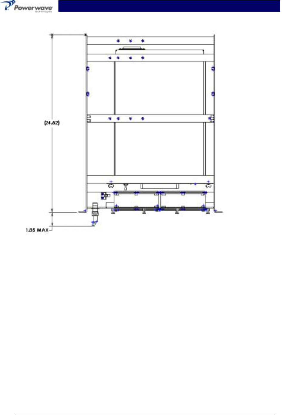
Designed to function as a subrack (see Figures 1-2 thru 1-6) in the host base station, the enclo-
sure has a one inch (right and left side) flanged front panel and eight mounting holes (four on
each side) to secure the Subrack into place (refer to Figure 1-3 for mounting hole locations). To
aid in maintaining the system’s operating temperature, the BAS is equipped with two cooling fans
mounted on the front access door (see Figures 1-3 and 1-4). The G3L-900-50-005 amplifier dis-
places 1,672 BTUs of heat at full power. The G3L-900-60-005 amplifier displaces approximately
1,900 BTUs of heat at full power.
The composite input signal is applied to a 30dB 10W input attenuator, followed by a voltage vari-
able attenuator that is controlled via dip switches on the front panel (refer to table 1-1 and figure
4-1). The maximum composite input signal may not exceed +31dBm. The composite signal is
then fed to a two-way power splitter. The signals are applied to the amplifiers, and the amplifier
outputs are combined again (refer to Tables 1-2 through 1-7 for specifications). With both ampli-
fiers installed, the system provides 20dB of gain.
The BAS also houses a distribution printed circuit board (PCB) for internal power and alarm distri-
bution (refer to Appendix B). Accessible from the front panel is the DB9 external ALARM con-
nector, the RF IN and RF OUT type N connectors.
Additionally, the front panel provides access to the +27 Vdc POWER IN connector, visibility of the
two MCPA’s fault alarm LED indicators and the GAIN CTRL dip switch. Refer to table 1-1 for the
dip switch truth table and fiqure 1-1 for pin designations.
With the access door open, the two amplifier modules are visible. All solid-state, the MCPAs are
designed for parallel operation for high peak power output. Their modular construction and
unique and highly effective LED-based operational status and fault indicators help minimize
downtime. The turn-on and turn-off sequence of voltages are fully automatic, as is overload pro-
tection and recycling. Inadvertent operator damage from front panel manipulation is virtually im-
possible. Refer to Figures 1-7 and 1-8 for drawing views of the amplifier module.
PRELIMINARY Booster Amplifier Subrack System Integration Manual
044-05075 Rev. B 1-2 January 2001
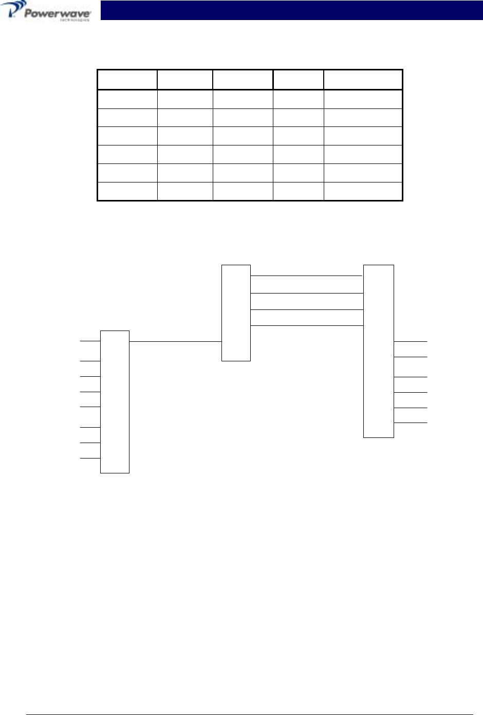
Table 1-1 Truth Table Input Variable Attenuator
Pin 1 Pin 2 Pin 3 Pin 4 Attenuation
+5Vdc +5Vdc +5Vdc +5Vdc 0dB
+5Vdc +5Vdc +5Vdc 0Vdc 1dB
+5Vdc +5Vdc 0Vdc +5Vdc 2dB
+5Vdc +0Vdc +5Vdc +5Vdc 4dB
+5Vdc +5Vdc +5Vdc 0Vdc 8dB
0Vdc 0Vdc 0Vdc 0Vdc 15dB
1
2
3
4
5
6
7
8
1
2
3
4
5
1
2
3
4
5
6
7
8
9
10
+5Vdc OUTPUT
GND
GND
GND
GND
INPUT
Vout
GND
GND
NC
NC
GND
GND
+27Vdc (Vin)
VOLTAGE
REGULATOR
DIP SWITCH
SOCKET VARIABLE
ATTENUATOR
Figure 1-1 Variable Attenuator, Voltage Regulator and Dip Switch Socket Pin Configuration
1-3 Functional and Physical Specifications
The BAS system’s functional and physical specifications are listed in table 1-2. A functional block
diagram is provided in section 4 of this manual to illustrate the system’s operational layout.

PRELIMINARY Booster Amplifier Subrack System Integration Manual
044-05075 Rev. B 1-3 January 2001
1-3.1 MCR20930-1-2 Subrack Specifications
Table 1-2 MCR20930-1-2 Booster Amplifier Subrack System Specifications
Frequency 935-940 MHz
Gain +20 dBm, ± 0.2 dBm
RF Input Power +31 dBm composite w/variable attenuator set to 0dB at-
tenuation.
+46 dBm composite w/variable attenuator set to 15 dB at-
tenuation.
RF Output Power:
G3L-900-50-005
G3L-900-60-005
43.5 Watts (+46.39 dBm) nominal, 1 module
75.8 Watts (+48.80 dBm) nominal, 100 W (max.), 2 modules
52.3 Watts (+47.18 dBm) nominal, 1 module
91.0 Watts (+49.59 dBm) nominal, 120 W (max.), 2 modules
Phase Variation ± 5°
Alarms +5 Vdc TTL
D.C. Power + 27 Vdc, 55 Amps max
Total System Return Loss -19 dBm
Channel Spacing 12.5 KHz
Operating Temperature 0 to 65 degrees C
Subrack Dimensions 12.22(H)x*17(W)x24.5(D) inches
Weight (Fully assembled) Approximately 80 Pounds (36.28 kilograms)
*Note: Does not include 1-inch right and left side mounting flanges.

PRELIMINARY Booster Amplifier Subrack System Integration Manual
044-05075 Rev. B 1-4 January 2001
Table 1-3 Electrical Specifications for 2-Way Splitter
Insertion Loss -33dB Min. (TBD on actual part)
-48dB Max.
Amplitude Balance ±0.2dB Max.
Insertion Loss Flatness Over Frequency ±0.3dB Max.
Input/Output Return Loss -20dB Min.
Port to Port Phase Delta ±5 Degrees Max.
Port to Port Isolation -20.0dB Min.
IP3 (Input Power = 5dBm) -90dBc Min.
Power Handling (Fixed Attenuator) 20 Watts Max.
Power Handling (Variable Attenuator) 3.16 Milliwatts Max.
Table 1-4 Electrical Specifications for 2-Way Combiner
Insertion Loss -0.6 dB (TBD on actual parts)
Amplitude Balance ±0.2dB Max.
Insertion Loss Flatness Over Frequency ±0.3dB Max.
Input/Output Coupled Port Return Loss -18.0 dB Min.
Port to Port Phase Delta ±5 Degrees Max.
Port to Port Isolation -20.0dB Min.
.
Power Handling 120 Watts
Sampling Coupler -25dB ±1dB
Sampling Coupler Directivity -18.0 dB Min.
IP3 (Input Power = TBD) -100 dBc Min

PRELIMINARY Booster Amplifier Subrack System Integration Manual
044-05075 Rev. B 1-5 January 2001
1-3.2 GL3-900 Series Amplifier Sprecifications
Table 1-5 G3L-900 Series Amplifier’s Electrical Specifications
Frequency Range 935-940 MHz
Channel Spacing 12.5 KHz
Output Power:
GL3-900-50-005
GL3-900-60-005 +47 dBm (50 Watts) nominal, 60 Watts (max.)
+47.8 dBm (60 Watts) nominal, 75 Watts (max.)
Input Power -10.0 dBm max.
RF Gain
GL3-900-50-005
GL3-900-60-005 +58.8 dB ±1.0 dB @ +27Vdc, 25 C.
+58.8 dB ±1.0 dB @ +27Vdc, 25 C
RF Gain Flatness over the
operating frequency range ±0.1 dB over any 1.25 MHz (over the frequency range).
Gain Flatness: ±0.5 dB (935 MHz – 942 MHz)
Normal Operating Voltage +27 Vdc ±1V Nominal (±5%) 1Vpp ripple (100-120 Hz) max.
Current Consumption:
GL3-900-50-005
GL3-900-60-005 20 Amps @ 27 Vdc, 25 °C, Prf = 50 Watts average
27 Amps @ 27 Vdc, 25 °C, Prf = 50 Watts average
Abnormal Operating Voltage +21 Vdc to below +26 Vdc. Above +28 Vdc to +29 Vdc.
RF Gain variation by Temp &
Voltage
TBD
Gain Variation Over Dynamic
Range ±0.1 dB max./20 dB for 0 to –20 dB rated power output
Intermodulation Distortion
In-Band Spurious
-65 dBc min. (Main signal power to Spurious @ (12.5 kHz)
-55 dBc min @ +23 to +24 Vdc
Input/Output VSWR. 1.5: 1 max @ 65 ± ºC.
Load Stability Infinite VSWR. all phases
Output Isolation 20 dB min. (shall incorporate an output isolator)

PRELIMINARY Booster Amplifier Subrack System Integration Manual
044-05075 Rev. B 1-6 January 2001
Table 1-6 G3L-900 Series Amplifier’s Mechanical Specifications
Items Specifications
Physical Dimension of
MCPA Front panel: 342.5mm(W) x 99mm(H) x 3mm(D)
Body: 288.8mm(W) x 95.3mm(H) x 446mm(D)
Weight Approximately 28.6 pounds (13 killograms)
Connector Type D-sub, Hybrid, Plug-in Type RF connector: PKZ 26-0020 series
straight plug type (Phoenix Co.) refers to attached drawing.
MCPA Front Panel Switch CKT Breaker. +27 Vdc Power Indicator
Pin Outs
A1 RF Input (Coaxial Contact)
A2 Ground (Power Contact)
A3 +27 Vdc (Power Contact)
A4 RF Output (Coaxial Contact)
1 TX H 10 +27 V
2TX L 11COM SV
3 GND 12 AMP AO
4RX H 13AMP A1
5RX L 14AMP A2
6 GND 15 AMP A3
7 HERE LPA 16 NC
8 FF LPA 17 NC
Connector
Description
9 RESERVED
Markings TBD
Front Panel LED Display LED type: SMD
RUN GREEN (When MCPA is enabled)
ALM Red (When any alarm occurred, LED is on)
DC Green (When DC Power is ON, LED is on)
MCPA Captive fastener TBD
Front Panel color & silk TBD

PRELIMINARY Booster Amplifier Subrack System Integration Manual
044-05075 Rev. B 1-7 January 2001
Table 1-7 Environmental Specifications for G3L-900 Series Amplifiers
Items Specifications
Operating Temperature 0 to + 65 C
Storage Temperature -40 to + 85 C
Relative Humidity 5 to 90% RH (non-condensing)
Operating Air Pressure 860 to 1060 mbar
Shock 40 m/s s* @ 22 ms half sinusoid shock
Pressure Integral forced air cooling must operate correctly at
up to 0.3 inches back.
Vibration Bellcore TR-NWT-000063 (1 m/s*s0.1∼200Hz)
Corrosion Resistance/ Salt Fog The MCPAs shall comply with the requirements of
Bellcore Technical Reference TA-NWT-000487, Is-
sue 2, Section 4.12
Altitude All specifications shall be met at an altitude up to
15,000 feet where the maximum external ambient
temperature is decreased by 0.5 C/ 1000 feet above
sea level. The MCPAs shall not sustain damage
when being transported at altitude up to 40,000 feet
or uniformly applied pressure to 30 PSIA.

PRELIMINARY Booster Amplifier Subrack System Integration Manual
044-05075 Rev. B 1-8 January 2001
1-4 Booster Amplifier Subrack (BAS) System Major Components
Table 1-8 lists the model numbers and descriptions of the major components that comprise the
BAS system and the document number (if available) of the manual related to each component.
Table 1-8 Major BAS System Components
Model/PN Description Qty Per
System
Expandable
To
800-01292-001 Top Assembly, BAS II w/o
Combiner Backplane 11
800-01294-001 Front Panel Assy 1 1
700-00901-001 Cable Assy, Power In 1 1
700-00902-001 Cable Assy, Amp Power 1 1
700-00903-001 Cable Assy, Amp Power 1 1
700-00904-001 Cable Assy, Fan 2 2
700-00905-001 Cable Assy, Amplifier 1 1
800-001296-001 Fan Assy 2 2
800-01297-001 Tray Assy 1 1
500-01425-001 PCB Assy, Power Distribution 1 1
MCR20930-1-2 Booster Amplifier Subrack 1 1
GL3-900-50-005 or
GL3-900-60-005 50-Watt Amplifier
60-Watt Amplifier 2
22
2
1-5 Equipment Changes
Powerwave Technologies, Inc. reserves the right to make minor changes to the equipment, in-
cluding but not limited to component substitution and circuitry changes. Changes that impact this
manual may be incorporated in a later revision of the manual.
PRELIMINARY Booster Amplifier Subrack System Integration Manual
044-05075 Rev. B 1-9 January 2001
Figure 1-2 Booster Amplifier Subrack System – Top View

PRELIMINARY Booster Amplifier Subrack System Integration Manual
044-05075 Rev. B 1-10 January 2001

PRELIMINARY Booster Amplifier Subrack System Integration Manual
044-05075 Rev B 2-1 January 2001
Section 2. Installation
2-1 Introduction
This section contains unpacking, inspection, installation instructions and recommendations for the
Booster Amplifier Subrack (BAS) System. It is important that the licensee perform the following
tasks correctly and in good faith:
1. Carefully read all material in this section prior to equipment unpacking or installation.
2. Also, read and review the operating procedures in section 3 prior to installing the equipment.
3. If applicable, carefully review the Federal Communications Commission (FCC) rules as they
apply to your installation. DON'T TAKE CHANCES WITH YOUR LICENSE.
2-2 Site Survey
Powerwave Technologies recommends that site surveys be performed by qualified individuals or
firms prior to equipment ordering or installation. Performing a detailed site survey will reduce or
eliminate installation and turn-up delays caused by oversights. Pay particular attention to power
plant capacity, air conditioning needs, and RF/DC cabling/breaker requirements.
2-3 Electrical Service Recommendations
Powerwave recommends that:
! Proper AC line conditioning and surge suppression be provided on the primary AC input to the
+27 Vdc power source.
! All electrical service should be installed in accordance with the National Electrical Code, any
applicable state or local codes, and good engineering practice.
! Straight, short ground runs be used.
! The electrical service must be well grounded.
Circuit breakers should be thermal type, capable of handling the anticipated inrush current, in a
load center with a master switch.
2-4 Air Conditioning
Each GL3-900-50-005 and GL3-900-60-005 amplifier generates 1672 BTUs and 1900 BTUs of
heat respectively at full power. A fully populated MCR20930-1-2 Booster Amplifier Subrack sys-
tem operating at full power will generate 3344 BTU's of heat (using two GL3-900-50-005 amplifi-
ers) and 3800 BTUs (using two GL3-900-60-005) amplifiers. At least a 1/3-ton air conditioner is
needed to cool this Powerwave equipment.

PRELIMINARY Booster Amplifier Subrack System Integration Manual
044-05075 Rev B 2-2 January 2001
Unpacking and Inspection
This equipment (as applicable) has been operated, tested and calibrated at the factory. Carefully
open and remove the MCPAs and model MCR20930-1-2 Booster Amplifier Subrack (BAS) from
their respective containers. Retain all packing material that can be reassembled in the event that
the unit must be returned to the factory. Please perform the following steps:
CAUTION
Exercise care in handling equipment during inspection to prevent damage caused by
rough or careless handling.
1. Visually inspect the MCPAs and the BAS for damage that may have occurred during ship-
ment.
2. Check for evidence of water damage, bent or warped chassis, loose screws or nuts, or extra-
neous packing material in the connector(s).
CAUTION
Before applying power, make sure that all connectors to the BAS components are
secure. Make sure that the input and output of the BAS are properly terminated at 50
ohms. Do not operate the system without a load attached. Refer to section 1, table 1-
2 for input power requirements. Excessive input power may damage the equipment.
If possible, inspect the equipment in the presence of the delivery person.
If the equipment is damaged:
! The carrier is your first area of recourse.
! A claim should be filed with the carrier once the extent of any damage is assessed. We can-
not stress too strongly the importance of IMMEDIATE careful inspection of the equipment and
the subsequent IMMEDIATE filing of the necessary claims against the carrier if necessary.
If the equipment is damaged and must be returned to the factory:
! Please write or phone for return authorization. Refer to section 6-3.1 of this manual for in-
structions.
! Powerwave may not accept returns without a return authorization.
Claims for loss or damage may not be withheld from any payment to Powerwave nor may any
payment due be withheld pending the outcome thereof. WE CANNOT GUARANTEE THE
FREIGHT CARRIER'S PERFORMANCE

PRELIMINARY Booster Amplifier Subrack System Integration Manual
044-05075 Rev B 2-3 January 2001
2-5 Installation Instructions
The model MCR20930-1-2 Booster Amplifier Subrack (BAS) is designed for use in a
2-way transceiver paging base station. The host enclosure must permit access to the subrack for;
DC power, RF and monitor cables. As well as, proper ventilation. The BAS system is designed
for an enclosure with at least 36 inches of depth. Please proceed with installation as follows:
WARNING
Verify that all circuit breaker switches on the subrack are in the OFF position. Turn
off external primary DC power before connecting DC power cables.
1. Install the subrack into the host base station and secure it into place using #10 32x1/2 Phil-
lips screws and #10 flat washers.
2. Connect POWER IN (+27 Vdc) to the subrack. Refer to figure 2-1 for pin locations and Ta-
ble 2-2 for pin designations.
3. Connect RF IN cable to the subrack.
4. Connect RF OUT cable to the subrack.
5. Connect external ALARM interface to external summary board. Refer to figure 2-2 for pin
locations and table 2-4 for pin designation.
6. Loosen thumbscrews to the front access door and open the door.
7. Before installing the MPCA into the subrack, inspect the 21-pin D-sub male combo connector
on the rear of each amplifier. Verify that all pins are straight, no pins are recessed, and that
the alignment shield is not bent.
8. Place power ON/OFF switch on the MCPA’s front panel in the “off” (far-left) position.
WARNING
Do not slam amplifiers into the subrack. Forcing the amplifier into the surack at too
fast a rate may cause the pins on the 21-D-sub conector of the amplifier to become
recessed or broken.
9. Insert a plug-in MCPA into the subrack. Tighten thumbscrews.
10. Repeat steps 7, 8 and 9 for the second MCPA.
WARNING
Check your work before applying DC voltage to the system. Make certain all
connections are tight and correct.
11. Measure primary DC input voltage. DC input voltage should be +27 Vdc ±1.0 Vdc. If the DC
input voltage is above or below the limits, call and consult Powerwave before you turn on your
amplifier system.
12. Refer to section 3 for initial turn-on and checkout procedures.
PRELIMINARY Booster Amplifier Subrack System Integration Manual
044-05075 Rev B 2-4 January 2001
2-6 Amplifier Module Power, Alarm, Control, and RF Connector
The power, alarm, control, and RF connections on the amplifier are made through a 21WA4 male
connector and are listed and described in table 2-1 below and in section 1, table 1-4.
Table 2-1 MCPA Alarms & Controls
Items Specifications Remarks
Alarms & Controls TTL Level; +5 Volts
Buffer: 74ABT244 (5V) - recommended
Deletion Alarm When unit does not exist (HEAR_PAU)
Equipped: GND Deletion OPEN D-Line
Function Fail Alarm When unit does not exist (HEAR_PAU)
Normal: High Abnormal GND D-Line
VSWR Alarm 3:1 (6dB ± 1dB) @ 35dBm-48dBm Output Power. PAU
remains normal operation when this alarm condition
disappears (NOT shutdown)
RS-485
High Temp. Alarm This alarm only at +75ºC. +5
ºC/
/-0
ºC RS-485
Over Power Output
Alarm @output power is greater than +48.5 dBm ±0.5dB.
MCPA will recover when the alarm condition disap-
pears. (NOT shutdown).
RS-485
DC Fail Alarm @ +20.5 Vdc ± 0.5V or +29 Vdc ± 0.5V. When this
alarm occurs the MCPA shall shut-down RS-485
Loop Fail Alarm When an alarm occurs on the feed forward path. RS-485
EN/DISABLE Reserved RS-485
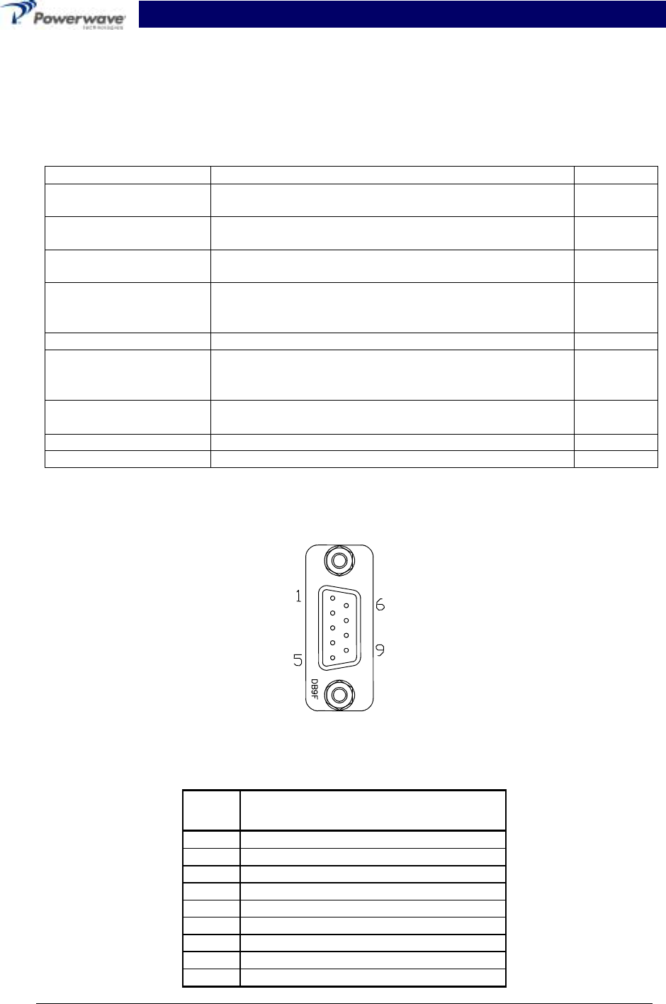
The Alarm Interface connector on the front panel of the MCR20930-1-2 Booster Amplifier Subrack
is a 9-pin female D-sub connector that permits serial interface with the external alarm monitor.
Refer to figure 2-1 and table 2-3 for connector definition.
Figure 2-1 J5 Alarm Connector
Table 2-2 J5 Alarm Connector Pin Designation
Pin Description
1 HERE_PAU-1
2 FF_PAU-1
3 DC_ON/OFF_1
4 PAU_RST_1
5 HERE_PAU_2
6 FF_PAU_2
7 DC_ON/OFF_2
8 PAU_RST_2
9 No Connection (NC)
PRELIMINARY Booster Amplifier Subrack System Integration Manual
044-05075 Rev B 2-5 January 2001
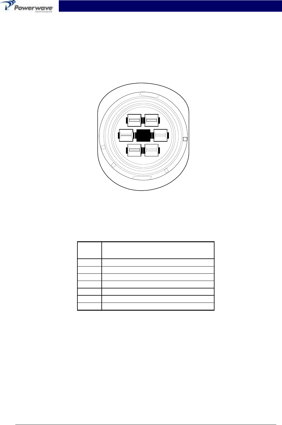
2-7 Remote Control and Status
Refer to table 2-3 for a description and list of remote control and status specifications for the
MCPA.
Figure 2-2 Front Panel POWER IN Connector
Table 2-3 Front Panel POWER IN Connector Pin Designations
Pin Description
1 +27Vdc
2 Ground
3 +27Vdc
4NC
5 +27Vdc
6 Ground
7 Ground
2
35
67
1
PRELIMINARY Booster Amplifier Subrack System Integration Manual
044-05075 Rev B 2-6 January 2001
Table 2-4 Remote Control and Status
Items Specifcations
RS-485
Physical
Layer
Each MCPA shall support an RS-485 multi-drop differential serial asynchro-
nous communications link operation at 9600 baud, 1 bit start, 8 bit data, 1
bit parity, 1 bit stop bit. The host shall terminate the RS-485 differential re-
ceive and transmit lines with 120 ohms. Because this communications bus
is also shared with other system resources. The MCPA is required to sup-
port the following asynchronous packet format communications protocol.
Packet format used for both commands and responses.
Byte Field Description
0 Source ID Address of Source
1 Destination ID Address of Destination
2 CMND/ ECHO Command/ Echo field
Asyn-
chronous
Packet
Protocol
Each MCPA shall receive but IGNORE any data packet NOT ADDRESSED
to itself. The receiver must reset its state machines and ready itself to
Receive the start of the next packet if it observes no activity on its RS-485
receive lines in 50 ms.
The CMND/ ECHO byte is used to send commands from host to MCPA as
follows:
Byte Field Description
0 Source ID Address of Source
1 Destination ID Address of Destination
-b(7): 0
-b(4:6): PAS ID
-b(0:3): PAU slot ID
2 CMND Command Field
CMND/ ECHO=
00H Report status
Address
01H-ffH Reserved
MCPA responses always echo the received CMND bytes as an ECHO byte of the
response packet.
Byte Field Description
0 Source ID -b(7): 0
-b(4:6): PAS ID
-b(0:3): PAU slot ID
1 Destination ID Address of Source
-b0: 1= High VSWR
condition/ 0=normal
-b1: 1=High Temperature
condition/ 0=normal
-b2: 1=Over Power
condition/ 0=normal
-b3: 1=DC fail
condition/ 0=normal
-b4: 1=Loop alarm
condition/ 0=normal
Response
from PAU
2 Report Data
-b5: 1=PAUenable
Condition/ 0=normal
-b6: reserved (0)
-b7: reserved (0)

PRELIMINARY Booster Amplifier Subrack System Integration Manual
044-05075 Rev. B 3-1 January 2001
Section 3. Operating Instructions
3-1 Introduction
This section contains operating instructions for Powerwave’s Booster Amplifier Subrack (BAS)
system.
3-2 Initial Start-Up and Operating Procedures
To perform the initial start-up, proceed as follows:
1. Double check to ensure that all input and output cables are properly connected.
CAUTION
Before applying power, make sure that the input and output of the amplifier are
properly terminated at 50 ohms. Do not operate the amplifier without a load attached.
Refer to table 1-1 for input power requirements. Excessive input power may damage
the MCPA
NOTE
The output coaxial cable between the amplifier and the antenna must be 50 ohm
coaxial cable. Use of any other cable will distort the output.
2. Turn on the supply that provides +27 Vdc to the amplifier system.
3. Place the power ON/OFF switch on the amplifier front panel in the “ON” (middle)
position.
4. Close the front access door. Tighten the thumbscrews.
5. Ensure that the GAIN CTRL dip switch is set at minimum gain (maximum attenua-
tion). Refer to section 1, table 1-1 for the dip switch’s truth table.
6. Allow the amplifiers to warm up for at least 5 minutes before taking power readings.
7. Refer to appendix C for the power setting procedure.
PRELIMINARY Booster Amplifier Subrack System Integration Manual
044-05075 Rev. B 4-1 January 2001
Section 4. Principles of Operation
4-1 Introduction
This section contains a functional description of Powerwave Technologies Inc.’s, Booster Ampli-
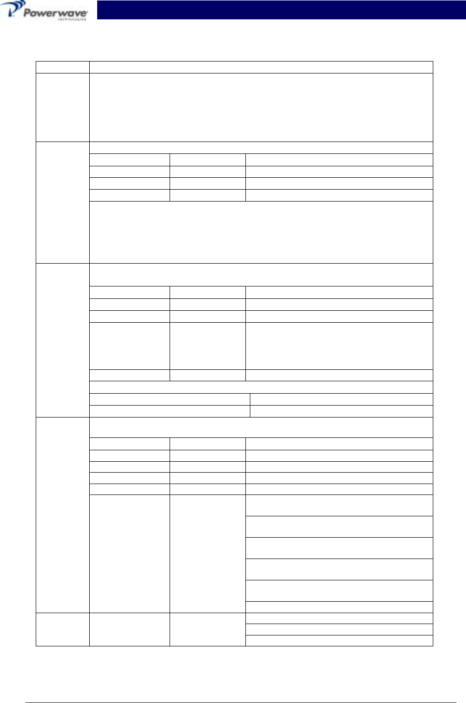
fier Subrack (BAS) system. Refer to figure 4-1 for the system’s functional block diagram.
4-2 RF Input Signal
The maximum input power for all carrier frequencies to the system should not exceed the limits
specified in section 1, table 1-2.
4-3 RF Output Load
The load impedance should be as good as possible (VSWR of 1.5:1 or better) in the working band
for good power transfer to the load. If the amplifier is operated into a filter, it will maintain its dis-
tortion characteristics outside the signal band even if the VSWR is infinite, provided the reflected
power does not exceed one Watt. A parasitic signal of less than one-Watt incident on the output
will not cause distortion at a higher level than the normal forward distortion (i.e. –65 dBc).
MCR 20930-1-2 MCR 20930-1-2
MCPA
MCPA
RS-485 Alarm
Interface
VVA
C
o
m
b
i
n
e
r
GAIN
CTRL Splitter
Distribution
Circuit
Board
(DC,Fans,
Alarms)
ISO
ISO
-25dB
Sample
DB9
Alarm
Alarm
Ctrl
2x +27VDC
2x Ground
RF Input
RF Output
GL3-900-50-005
GL3-900-60-005
30 dB
Figure 4-1 System Block Diagram
4-4 System Functional Discription
Designed as a subrack for installation in a 2-way transceiver paging base station, the BAS system
is comprised of a MCR20930-1-2 Booster Amplifier Subrack (BAS) and two G3L-900-50-005 or
G3L-900-60-005 plug-in multi-carrier power amplifiers (MPCAs).
Additionally, the BAS houses a two-way power splitter/combiner and a distribution printed circuit
board (PCB). Refer to Appendix A for pinout locations. The RF IN, RF OUT, +27 Vdc and the
ALARM summary connector, interface with the host system via front panel cabling.
The RF input signal is split equally and applied to the plug-in amplifiers. The output from each
amplifier is an amplified composite signal (refer to table 1-5 for amplifier output specifications). All
phase and gain corrections are performed on the signal(s) in the individual amplifier. The ampli-
fier outputs are fed to a power combiner and combined to form a composite RF output (refer to
table 1-5). Refer to figure 4-1 for the System Functional Block Diagram.
PRELIMINARY Booster Amplifier Subrack System Integration Manual
044-05075 Rev. B 4-2 January 2001
The distribution printed circuit board (PCB) assembly is used to distribute power to the BAS sys-
tem’s internal components. The PCB circuit is a DC/DC converter designed to convert the +27
Vdc input to +12 Vdc and +15 Vdc. Refer to Appendix B for pinout location.
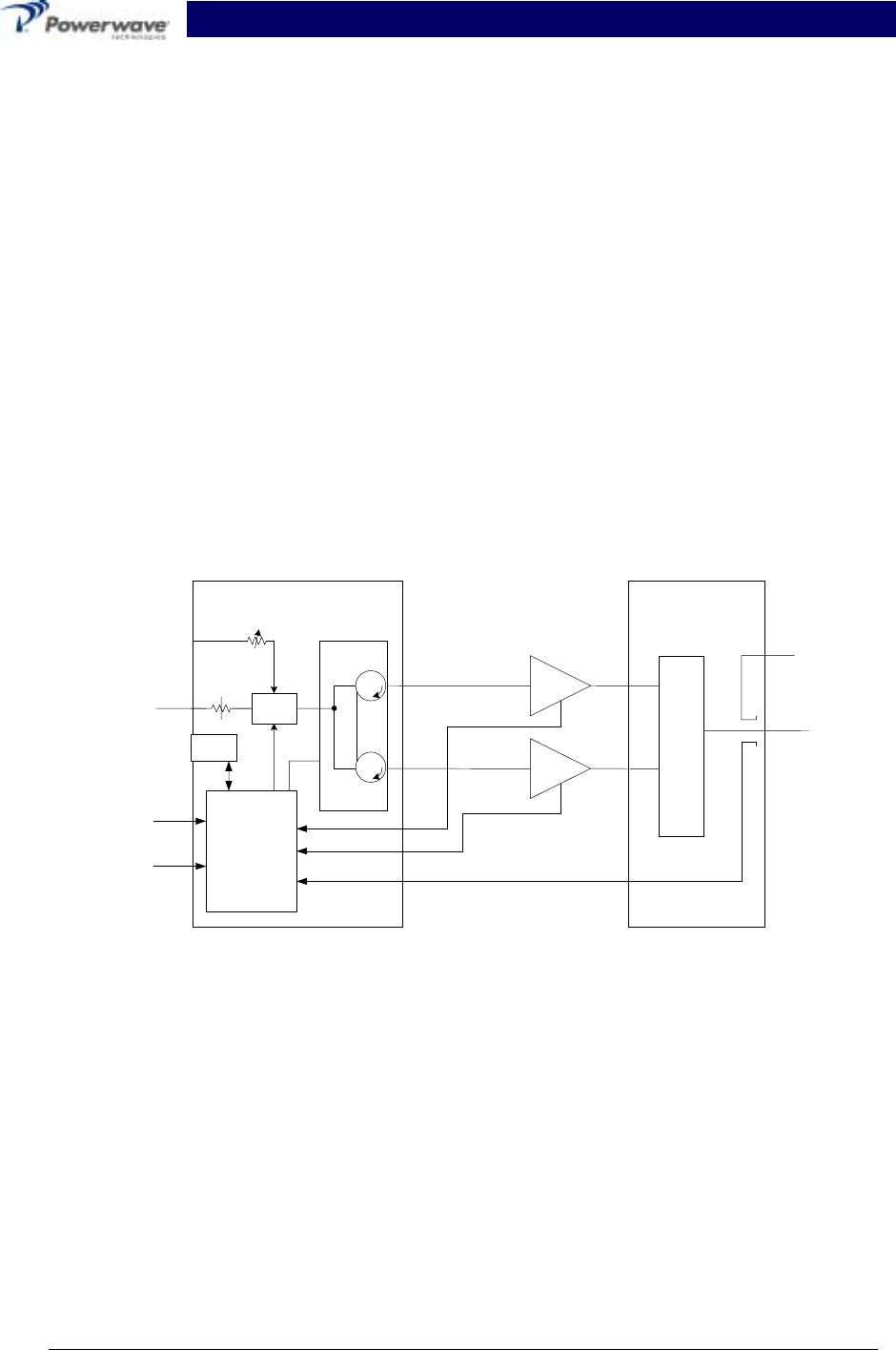
4-5 Multi-Carrier Power Amplifier (MCPA) Functional Description
The MCPA is a linear, feed-forward multi-carrier power amplifier that operates in the 5 MHz fre-
quency band from 935 MHz to 940 MHz (refer to table 1-5 for amplifier specifications). Each am-
plifier is a self-contained module and is functionally independent of the other MCPA in the system.
The amplifiers are designed for parallel operation to achieve high peak power output (refer to Ta-
ble 1-2 for MPCA power specifications). Each MCPA has an alarm board that monitors the ampli-
fier performance. If a failure or fault occurs in an MCPA, it is transmitted to the host system via
the D-subminiature 21WA4 connector at the rear of the module. A warning light (LED), which is
routed from the amplifier via the J7 connector on the PCB to the front panel of the BAS, will illumi-
nate. The indicator LEDs are identified as Alarm 1 and Alarm 2 which corresponds to their re-
spective amplifier..
The amplifier is compliant to the requirements of FCC Part 90 with respect to spurious emissions.
Constant gain is maintained by continuously comparing active paths with passive references, and
correcting for small variations through the RF feedback controls. All gain variations, for example
those due to temperature, are reduced to the passive reference variations. The amplifier is com-
prised of:
A preamp
A driver amplifier
A main amplifier
An error and pre-error amplifier
Alarm monitoring and control
Pre
Amp
Pre
Main Main
Amp
Error
Amp
Delay
Feed Forward Loop control
2nd Loop
Phase & Gain
1st Loop
Phase & Gain Delay
Alarms & Display
+15 +5 -5
Power Supply
-30dB -10dB
-40dB
RF Out
RFL
PWR
FWD
PWR
Front Panel
Smart Rack
+27VDC
Figure 4-2 Multi-Carrier Power Amplifier Functional Block Diagram

PRELIMINARY Booster Amplifier Subrack System Integration Manual
044-05075 Rev. B 4-3 January 2001
4-5.1 Predriver Amplifier
The input of the amplifier uses two stages of class AB amplification which provide approximately
13.5 dB of gain in the 5 MHz frequency band from 935 MHz to 940 MHz. The amplifier operates
on +27 Vdc.
4-5.2 Three-Stage Driver Amplifier
The input of the amplifier uses three stages of class AB amplification which provide approximately
32 dB of gain in the 5 MHz frequency band from 935 MHz to 940 MHz. The amplifier operates on
+27 Vdc, and a bias voltage of +5 Vdc. The logic controls the +5 Vdc bias voltage that shuts
down the amplifier.
4-5.3 Main Amplifier
The signal provides approximately 11 dB of gain in the 935 to 940 MHz frequency band (refer to
table 1-5 for amplifier specifications). The main amplifier operates on +27 Vdc, and a bias voltage
of +5 Vdc. The alarm logic controls the +5 Vdc bias voltage that shuts down the amplifier.
The main amplifier employs class AB amplification for maximum efficiency. The error amplifier
and feed forward loops are used to correct signal non linearities introduced by the class AB main
amplifier. The error amplifier operates in class A mode. The RF input signals are amplified by a
preamp and coupled to an attenuator and phase shifter in the first feed-forward loop. The main
signal is phase shifted by 180 degrees and amplified in the premain amplifier. The output from
the premain amplifier is fed to the class AB main amplifier.
The signal output from the main amplifier is sampled using a coupler, and the sample signal is
combined with the main input signal and input to the second feed-forward loop. The error signal is
attenuated, phase shifted 180 degrees, then fed to the error amplifier where it is amplified to a
level identical to the sample output from the main amplifier. The output from the error amplifier is
then coupled back and added to the output from the main amplifier. The control loops continu-
ously make adjustments to cancel out any distortion in the final output signals.
4-5.4 Alarm Monitoring and Control
During routine operation, all normal variations are automatically compensated for by the feed-
forward loop control. However, when large variations occur beyond the adjustment range of the
loop control, a loop fault will occur. When this happens, the ALARM LED is illuminated on the
front panel of the subrack. The fault is transmitted back to an external summary module via the
external ALARM interface connection on the front panel of the subrack.
4-5.5 Loop Control Circuit
The primary function of the first loop is to provide an error signal for the second loop. The primary
function of the second loop is to amplify the error signal to cancel out spurious products devel-
oped in the main amplifier. The input signal is amplified by a preamplifier and fed to a coupler and
delay line. The signal from the coupler is fed to the attenuator and phase shifter in the first loop.
The first loop control section phase shifts the main input signals by 180 degrees and constantly
monitors the output for correct phase and gain.
The second loop control section obtains a sample of the distortion added to the output signals by
the main amplifiers. The signal is phase shifted 180 degrees, then fed to the error amplifier where
it is amplified to the same power level as the input sample. The signal is then coupled to the error
signal on to the main output signal. The final output is monitored by the second loop and adjusted
to ensure that the signal distortion and intermodulation distortion (IMD) on the final output is can-
celled out.

PRELIMINARY Booster Amplifier Subrack System Integration Manual
044-05075 Rev. B 4-4 January 2001
4-6 Amplifier Module Cooling
Although each amplifier contains it own heat sink, it is cooled by forced air. Two fans mounted on
the front of the subrack are used for forced air cooling and redundancy. The fans draw air
through the front of the system and exhaust hot air out the back. The fans are field replaceable.
Each amplifier, when properly cooled, will provide sufficient cooling to maintain the amplifier within
the specified operating temperature range. Six inches of free space are required at both the front
and rear panels of the subrack to allow adequate air volume to circulate over the heat sinks.
4-7 Power Distribution
Primary DC power for the amplifier is provided by the host system. The amplifier module has a
DC/DC converter and voltage regulator that converts the +27 Vdc to +15 Vdc, +5 Vdc, and +8 Vdc
for internal use.

PRELIMINARY Booster Amplifier Subrack System Integration Manual
044-05075 Rev. B 5-1 January 2001
Section 5. Maintenance
5-1 Introduction
This section contains periodic maintenance and performance test procedures for Powerwave’s
Booster Amplifier Subrack (BAS) system.
NOTE
Check your sales order and equipment warranty before attempting to service or repair
the unit. Do not break the seals on equipment under warranty or the warranty will be
null and void. Do not return equipment for warranty or repair service until proper
shipping instructions are received from the factory.
5-2 Periodic Maintenance
Periodic maintenance requirements are listed in Table 5-1. Table 5-1 also lists the intervals at
which the tasks should be performed.
Table 5-1. Periodic Maintenance
Task Interval Action
Inspection
Cables and Connectors 12 Months Inspect signal and power cables for frayed insulation.
Check RF connectors to be sure that they are tight.
Performance Tests 12 Months Perform annual test per paragraph 5-5.
Clean Fans/Heat Sinks 3 Months Inspect for debri. Remove dust with a soft cloth/brush
or vacuum cleaner.
5-3 Test Equipment Required For Test
Test equipment required to test the amplifier is listed in table 5-2. Equivalent test equipment may
be substituted for any item, keeping in mind that a thermistor type power meter is required.
NOTE
All RF test equipment required must be calibrated to 0.05 dB resolution. Any
deviation from the nominal attenuation must be accounted for and factored into
all output readings.
Table 5-2. Test Equipment Required
Nomenclature Manufacturer Model
Signal Generator H.P. 8656B
20 dB Attenuator, 250 Watt Bird Tenuline
20 dB Attenuator, 20 Watt (2 each) Bird Tenuline
Spectrum Analyzer H.P. 8560E
Coax Directional Coupler H.P. 778D
Power Meter / Sensor H.P. 437B / 8481A
Arbitrary Waveform Generator Sony AWG2021
Network Analyzer H.P. 8753C
Source Diskette Powerwave

PRELIMINARY Booster Amplifier Subrack System Integration Manual
044-05075 Rev. B 5-2 January 2001
5-4 Performance Test
Performance testing should be conducted every 12 months to ensure that the amplifier system
meets the operational specifications listed in Table 5-3. Also verify system performance after any
amplifier module is replaced in the field. The test equipment required to perform the testing is
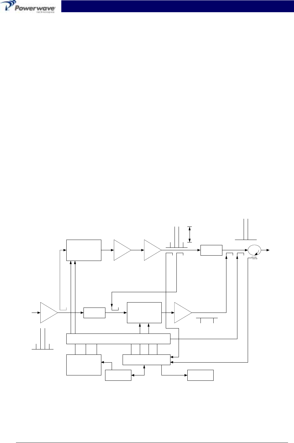
listed in table 5-2, and the test setup is shown in figure 5-1.
NOTE
The frequencies used in this test are typical for an amplifier with a 5 MHz band from
935 MHz to 940 MHz. Select evenly spaced F1, F2, F3, and F4 frequencies that
cover the instantaneous bandwidth of your system.
5-4.1 Amplifier Performance Test
To perform this test, proceed as follows:
Connect test equipment as shown in figure 5-1.
WARNING
Do not apply any RF signals at this time.
5-4.1.1 Amplifier Spurious Emissions Test:
With the RF input signal to the amplifier set to be as shown in Figure 5-1, use the spectrum ana-
lyzer to measure the spurious emissions performance. Record test data in Table 5-3. Verify that
it is within the specifications shown in table 1-2. Switch tested amplifier to OFF.
5-4.1.2 Gain Test:
1. Disconnect spectrum analyzer from test setup, and connect the network analyzer.
2. Set network analyzer as follows:
A. Power output to -13 dBm.
B. Frequency start to 935 MHz.
C. Frequency stop to 940 MHz.
D. Normalize the network analyzer for gain and return loss.
3. Check the amplifier gain across the band from 935 MHz to 940 MHz. Gain should be as
specified in table 1-2. Record test data in table 5-3.
5-4.1.3 Input Return Loss:
Read and record the S11 return loss measurement on network analyzer. Record test data in table
5-3.
PRELIMINARY Booster Amplifier Subrack System Integration Manual
044-05075 Rev. B 5-3 January 2001
Figure 5-1 Amplifier Test Setup Diagram

PRELIMINARY Booster Amplifier Subrack System Integration Manual
044-05075 Rev. B 5-4 January 2001
Table 5-3. Multi-Carrier Power Amplifier Test Data Sheet
DATE _________________________________
MODULE S/N___________________________
TEST CONDITIONS:
Load and Source Impedance: 50 Ohms
VSWR: < 1.2:1
Supply Voltage: +27 Vdc ±0.1 Vdc
TEST SPECIFICATION MIN MAX DATA
RF Gain Vcc = 27 Vdc
PO = See table 1-5
Freq. = 935 - 940 MHz
Table 1-2
-0.5 dB Table 1-2
+0.5 dB
Spurious
Emissions Vcc = 27 Vdc
PO = See table 1-5
935 - 940 MHz Band -65 dBc
Gain Flatness Vcc = 27 Vdc
PO = See table 1-5
935 - 940 MHz Band ±0.5 dB
Input Return
Loss Vcc = 27 Vdc
PO = See table 1-5
935 - 940 MHz Band -12 dB
PASS FAIL
Tested by

PRELIMINARY Booster Amplifier Subrack System Integration Manual
044-05075 Rev. B 5-5 January 2001
5-5 Field Replacement of the Module
The G3L-900-50-005 and GL3-900-60-005 multi-carrier power amplifier module can be replaced
in the field on site by a qualified technician with experience maintaining RF power amplifiers and
similar equipment:
To replace a power amplifier module, proceed as follows:
1. Set on/off switch on the front panel of the amplifier module to OFF (down).
2. Loosen the two thumbscrews that secure amplifier module to the subrack.
CAUTION
When removing the amplifier from the subrack, it is very important to support the
amplifier such that the rear of the module does not suddenly drop when the guide rail
disengages from the track. A drop such as this could damage the rear 21WA4
multipin connector.
3. With steady even pressure, use handle on front of amplifier to pull module out of subrack.
4. Install replacement in reverse order of steps 1 through 3 above.

PRELIMINARY Booster Amplifier Subrack System Integration Manual
044-05075 Rev. B 6-1 January 2001
Section 6. Troubleshooting
6-1 Introduction
This section contains a list of problems which users have encountered and a few suggested ac-
tions that may correct the problem. If the suggested corrective action does not eliminate the
problem, please contact your Powerwave field representative or the factory for further instructions.
NOTE
Check your sales order and equipment warranty before attempting to service or repair
the unit. Do not break the seals on equipment under warranty or the warranty will be
null and void. Do not return equipment for warranty or repair service until proper
shipping instructions are received from the factory.
6-2 Troubleshooting
Refer to table 6-1 for troubleshooting suggestions.
Table 6-1. Troubleshooting.
Symptom Suggested Action
Inoperative 1. Check for proper power supply voltages.
2. Verify all RF connections.
3. Contact your field representative.
MCR20930-1-2 Fan Noise 1. Locate noisy fan.
2. Check for damage
3. Replace noisy or damaged fan
G3L-900-50-005 or
GL3-900-60-005 Inoperative
1. Check for proper power supply voltage.
2. Verify all RF connections.
3. Verify that unit does not have a major fault (red LED on
front panel). Recycle power.
6-3 Return For Service Procedures
When returning products to Powerwave, the following procedures will ensure optimum response.
6-3.1 Obtaining An RMA
A Return Material Authorization (RMA) number must be obtained prior to returning equipment to
the factory for service. Please contact our Repair Department at (714) 466-1000 to obtain this
number, or FAX your request to (714) 466-5800. Failure to obtain this RMA number may result in
delays in receiving repair service.
6-3.2 Repackaging For Shipment
To ensure safe shipment of the amplifier, it is recommended that the package designed for the
amplifier be used. The original packaging material is reusable. If it is not available, contact Pow-
erwave’s Customer Service Department for packing materials and information.
PRELIMINARY Booster Amplifier Subrack System Integration Manual
044-05075 Rev. B A-1 January 2001
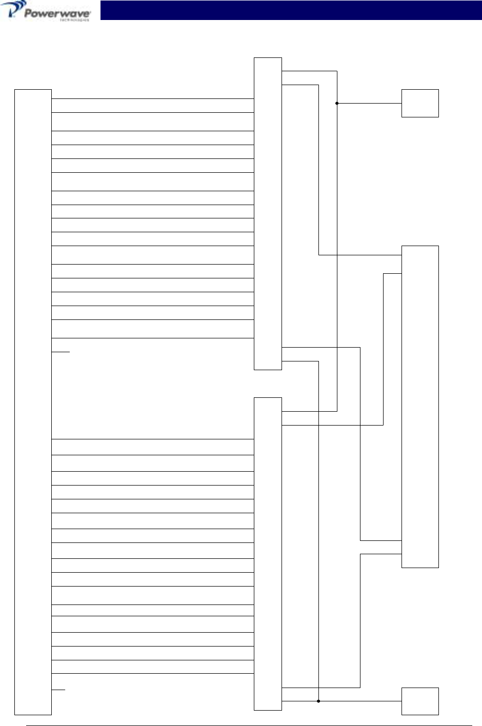
Appendix A. Booster Amplifier Subrack Backplane Wiring Diagram
1
20
2
21
3
22
4
23
5
24
6
25
7
26
8
27
9
28
10
29
11
30
12
31
13
32
14
33
15
34
16
35
17
36
18
37
A1
A2
1
2
3
4
5
6
7
8
9
10
11
12
13
14
15
16
17
A3
A4
A1
A2
1
2
3
4
5
6
7
8
9
10
11
12
13
14
15
16
17
A3
A4
(TX_H)
(TX_L)
GND
(RX_H)
(RX_L)
GND
(HERE_PAU)
(FF_PAU)
(DC_ONNOFF)
(PAU_RST)
(DIV_SW)
(COM_SW)
(AMP_A0)
(AMP_A1)
(AMP_A2)
LED_GRN ANODE
LED_RED ANODE
(TX_L)_2
GND_2
(RX_H)_2
(RX_L)_2
GND_2
(HERE_PAU)_2
(FF_PAU)_2
(DC_ONNOFF)_2
(PAU_RST)_2
(DIV_SW)_2
(COM_SW)_2
(AMP_A0)_2
(AMP_A1)_2
(AMP_A2)_2
LED_GRN ANODE_2
LED_RED ANODE_2
(TX_H)_2
NC
P2
AMP_1
AMP_2
A1
A2
1
2
3
4
5
6
7
8
9
1-
11
12
13
14
15
16
17
A3
A4
RF OUT
RF IN
RF INPUT
+27Vdc
GND
RF OUTPUT
RF INPUT
+27Vdc
GND
RF OUTPUT
NC
PRELIMINARY Booster Amplifier Subrack System Integration Manual
044-05075 Rev. B B-1 January 2001
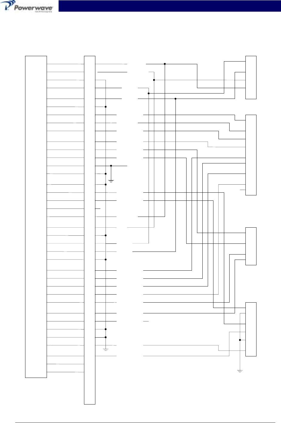
Appendix B. Distribution Printed Circuit Board
Pinout Location
1
20
2
21
3
22
4
23
5
24
6
25
7
26
8
27
9
28
10
29
11
30
12
31
13
32
14
33
15
34
16
35
17
36
18
37
19
1
2
3
4
5
6
7
8
9
10
11
12
13
14
15
16
17
18
19
20
21
22
23
24
25
26
27
28
29
30
31
32
33
34
35
36
37
38
39
40
DB37 PINOUT P4
1
2
3
4
1
2
3
4
5
6
7
8
9
1
2
3
4
5
6
1
2
3
4
TX_H
TX_L
TX_L
N/C
N/C
N/C
N/C
N/C
RX_H
HERE_PAU_1 J5
J4
J6
J7
ALARM
RS485
SPLITTER/COMBINER
FF_PAU_1
DC_ON/OFF_1
PAU_RST_1
DIV_SW_1
COM_SW_1
OTP1
(AMP_A0_1)
AMP_A1_1
AMP_A2_1
LED_GRN_1
LED_ RED_1
N/C
TX_H
RX_H
RX_L
RX_L
HERE_PAU_2
FF_PAU_2
DC_ON/OFF_2
PAU_RST_2
DIV_SW_2
COM_SW_2
AMP_A0_2 TP2O
LED_GRN_2
LED_RED_2 LED
NC

PRELIMINARY Booster Amplifier Subrack System Integra-
tion
044-05075 Rev. B C-1
1January 2001
Appendix C Power Setting Procedure
C-1 Power Setting Calculations:
1. Ensure the composite input power to the Powerwave MCR20930-1-2 is < 0 dBm.
2. Determine the required output level at the hatch plate per carrier (Analog, Digital, CDPD, and
Setup Channels). Follow the example after step 5 below.
3. Determine the amount of loss between the subrack output and the hatch plate.
A. Either the calculated value (Lucent uses 1.7dB for the Series II), or
B. Measure the loss
1. Key one radio and make a measurement in dBm at the front of the subrack with an HP
EPM-441A or equivalent power meter. Write the value down: _____ dBm.
2. Disconnect the radio and move the power meter to the hatch plate.
3. Key the same radio and make a measurement in dBm, and write it down: _____ dBm.
The difference between the two measurements is the loss.
4. Determine the amount of power output at the rear of the subrack per carrier.
5. Multiply the number of carriers times the output power level per carrier at the front of the subrack.
Three blank tables are provided on page 3 of this appendix for you to record your desired power
levels.
AB C D E FG
Hatch
Powe
r
(w)
Convert Hatch Power
to dBm
Loss from
Hatch to
Powerwave
Subrack (dB)
Power @ Powerwave
Subrack (dBm) Convert Powerwave Subrack
Power to watts No. of
Carriers Total Power
per Signal
(watts)
Formula a b=10*LOG(a / 0.001) c d=b+c e=x10(d/10)*0.001 f g=ef
Example
Analog 6.3 10*Log(6.3/0.001)=37.9934 1.7 37.9934 + 1.7 = 39.6934 x10(39.9934/10)*0.001=9.318
410 93.1838
CDMA* 21* 10*Log(21/0.001)=43.2222 1.7 43.2222 + 1.7 = 44.9222 x10(44.9222/10)*0.001=31.06
13 2 62.1226
CDPD 6.3 10*Log(6.3/0.001)=37.9934 1.7 37.9934 + 1.7 = 39.6934 x10(39.9934/10)*0.001=9.318
41 9.3184
Setup 6.3 10*Log(6.3/0.001)=37.9934 1.7 37.9934 + 1.7 = 39.6934 x10(39.9934/10)*0.001=9.318
41 9.3184
Inner
Tier 2.5 10*Log(2.5/0.001)=33.9794 1.7 33.9794 + 1.7 = 35.6794 x10(35.6794/10)*0.001=3.697
84 14.7911
Total
Power 188.7342
*Some RF Engineers will give the power for Pilot Page and Sync (on the order of 2 to 5W). Powerwave
normally multiplies this value by 7 for the purpose of roughly calculating the CDMA channel with full
traffic load.
If the total output power level at the front of the Powerwave subrack exceeds the subrack’s specified
capability with the number of populated amplifiers: Reduce the number of input radios until the
subrack power rating is met.
PRELIMINARY Booster Amplifier Subrack System Integra-
tion
044-05075 Rev. B C-2
2January 2001
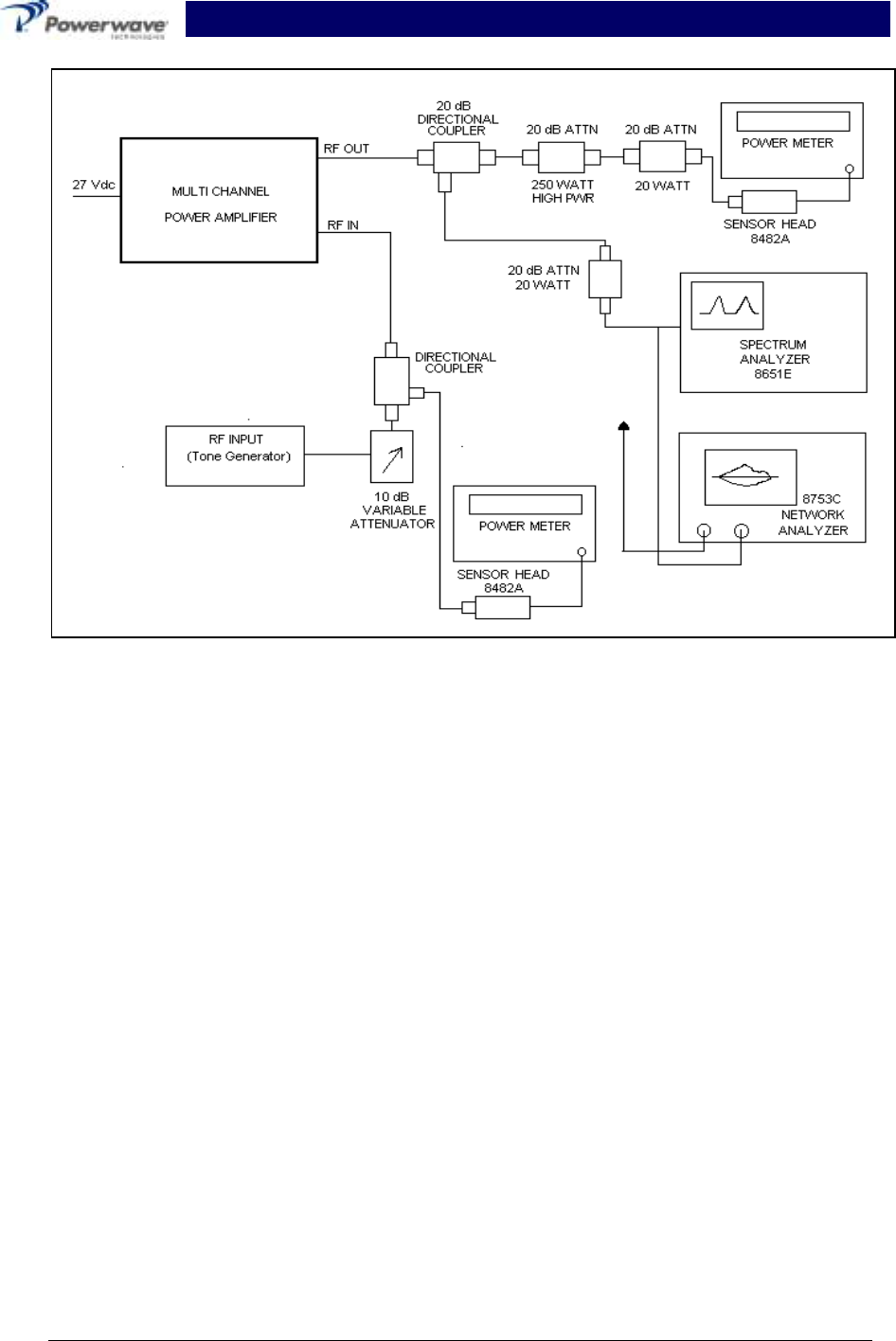
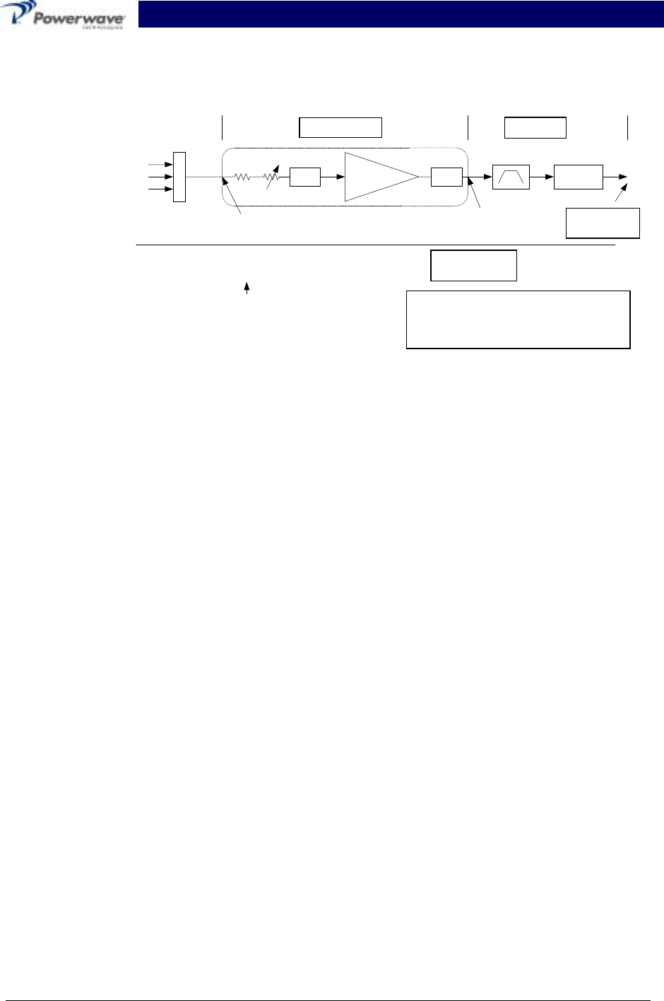
C-2 Power Setting Procedure:
Figure C-1 Gain Block Example
1. Set all transceiver levels to midrange output levels if this is a new base station installation. For
existing base stations, the levels may be left as they currently are set.
NOTE
The composite input level should not exceed -20dBm most applicatons. Higher input levels
may result in over-driving the MCR20930-1-2 amplifier subrack. Refer to section 1 for
individual model power specifications.
2. Ensure all radios are not transmitting, including CDPD.
3. Connect the power meter, with appropriate attenuators as necessary, to the transmit filter output
feed at the hatch plate.
4. Set the GAIN CTRL to minimum gain (maximum attenuation). Refer to section 1, table 1-1 for the
dip switch truth table.
5. Key one radio (usually this is the primary setup channel).
6. Set the output level using the GAIN CTRL on the Powerwave subrack and transmitter gain ad-
justment for this single channel. Normally, the CDMA channel has the most limiting range, so this
is the best channel to start with, although most technicians normally start with the setup channel.
Try to keep the adjustments in the middle of the available range adjustments.
7. Verify the power level is still correct.
8. Unkey the radio.
9. Key one radio at a time and set the power level of each individual radio at the hatch plate accord-
ing to the calculations made in the first section above. Do not readjust the GAIN CTRL level.
10. Unkey all radios.
C-2.1 Overpower Verification
11. Connect the power meter, with appropriate attenuators as necessary, to the RF output of the
Powerwave subrack.
12. Reconnect the transmit filter output cable to the antenna.
MCPA
58.8dBg
C
o
m
b
DC
~-1.7dB
49.59dBm
91W
5 to 20dB
Gain Avail.
7.5W
38.75dBm
11.09W
40.45dBm
111mW
20.45dBm
29.59dBm
910mW 47.89dBm
61.52W
Example:
Single Analog Ch
Composite
Maximum composite input
level if gain is set to
maximum (0 attenuation)
Values in Boxes are given or known.
The remaining values are calculated
based on the given values.
Splitter Comb.
-30dB

PRELIMINARY Booster Amplifier Subrack System Integra-
tion
044-05075 Rev. B C-3
3January 2001
13. Key all the radios and measure the total maximum power. This power level should not exceed the
rating for the MCR20930-1-2. If the power rating for the MCR20930-1-2 is exceeded, the in-
termodulation distortion performance of the amplifiers will suffer and the software-
overpower protection feature of the MCR20930-1 will activate.
NOTE:
Each amplifier will go into overdrive alarm when they are being driven 3 dB over
the rated power for that amplifier.
Each amplifier will shut down at 3 dB over the rated power, and possibly cause the
entire sector to be disabled.
Table C-1 Amplifier and Amplifier Subrack ratings
Amplifier 1 Module 2 Modules
GL3-900-50-005 43.5 W (46.39 dBm) nominal 75.8 W (48.80 dBm) nominal,
100 W (max)
GL3-900-60-005 52.3 W (47.18 dBm) nominal 91 W (49.59 dBm) nominal,
120 W (max)
All measurements should be made with a calibrated power meter accurate
within +2% (HP EPM-441A or equivalent)
14. Disconnect all the radios.
15. Reconnect the RF output coax cable to the Powerwave subrack.

PRELIMINARY Booster Amplifier Subrack System Integra-
tion
044-05075 Rev. B C-4
4January 2001
Hatch
Power
(w)
Convert Hatch Power
to dBm
Loss from Hatch
to Powerwave
Subrack (dB)
Power @ Powerwave
Subrack (dBm) Convert Powerwave
Subrack Power to
watts
No. of
Carriers Total Power per
Signal
(watts)
Formula a b=10*LOG(a / 0.001) c d=b+c e=x10(d/10)*0.001 f g=ef
Sector:
Total
Power
Hatch
Power
(w)
Convert Hatch Power
to dBm
Loss from Hatch
to Powerwave
Subrack (dB)
Power @ Powerwave
Subrack (dBm) Convert Powerwave
Subrack Power to
watts
No. of
Carriers Total Power per
Signal
(watts)
Formula a b=10*LOG(a / 0.001) c d=b+c e=x10(d/10)*0.001 f g=ef
Sector:
Total
Power
Hatch
Power
(w)
Convert Hatch Power
to dBm
Loss from Hatch
to Powerwave
Subrack (dB)
Power @ Powerwave
Subrack (dBm) Convert Powerwave
Subrack Power to
watts
No. of
Carriers Total Power per
Signal
(watts)l
Formula a b=10*LOG(a / 0.001) c d=b+c e=x10(d/10)*0.001 f g=ef
Sector:
Total
Power