Powerwave Technologies 5JS0054 RF Front End Multi-Carrier Power Amplifier System User Manual I GENERAL DESCRIPTION
Powerwave Technologies Inc RF Front End Multi-Carrier Power Amplifier System I GENERAL DESCRIPTION
manual

Draft RX 1850-1910 MHz; TX 1930-1945 MHz
044-05082 Rev. A March 2001
System Integration Manual
Radio Frequency Front End
Multi-Carrier Power Amplifier System

Draft RF Front End System Integraton Manual
044-05082 Rev. A ii March 2001
March 2001
Powerwave Technologies, Inc. Tel: (714) 466-1000
1801 E. St Andrew Place Fax: (714) 466-5800
Santa Ana, CA 92705 Web Site: www.powerwave.com
®
© 2001 Powerwave Technologies Incorporated. All rights reserved.
Powerwave Technologies, and the Powerwave logo are registered trademarks
Powerwave Technologies, Inc. reserves the right to make changes to the documentation and
equipment, including but not limited to component substitution and circuitry changes. Changes
that impact this manual may subsequently be incorporated in a later revision of this manual.

DRAFT RF Front End System Integration Manual
044-05082 Rev. A 1-1 March 2001
Section 1 General Discription
1-1 Introduction
This manual contains information and procedures for installation, operation, and maintenance of
the Radio Frequency Front End (RFFE) Multi-Carrier Power Amplifier (MCPA) System. This
manual is organized into sections as follows:
Section 1.General Description Appendix B: Amplifier Power Setting Procedure
Section 2. Installation Appendix C: General Site Survey Form
Section 3. Operating Instructions
Section 4. Principles of Operation
Section 5. Maintenance
Section 6. Troubleshooting
1-2 General Discription
Designed to compensate for cable loss due to long cable runs, the RFFE uses an AB amplifier
that utilizes a pre-distortion technique for linearization (see figure 4-3 for the amplifier block dia-
gram). Designed as a two unit system and equipped with a space diversity path to reduce fading,
the RFFE operates in the PCS frequency range of: 1850MHz to 1910MHz (receive) and 1930MHz
to 1945MHz (transmit): The system consists of.
• The Masthead Unit (MHU)
• The Masthead Unit Interface (MHUI)
1-2.1 The Masthead Unit
The primary function of the MHU is to provide maximum RF output power (not to exceed 100
Watts) with multiple CDMA carries into a matched 50 Ohm load while maintaining the spectral re-
growth and spurious requirements (see table 1-2). Supported by a mounting frame (see figure
1-2), the Mast Head Unit (MHU) is mounted on the antenna tower near the antenna and consists
of three modular components; the common box and two RF transmit (Tx) modules. each module
is encased in a weatherproof (NEMA 4) housing (refer to table 1-2 for environmental specifica-
tions).
1-2.1.1 The Common Box
The common box (see figure 1-4) connects to both Tx modules via blind mate connectors (refer to
figure 1-1 and table 1-1). It houses a redundant LNA path, two input duplexers, two output du-
plexers, two 27VDC (scalable up to 1200Watts) power supplies, and a control board.
1-2.1.2 The Transmitt Modules
Powered by 220VAC from the host breaker panel, the two RF transmit modules are used for re-
dundancy in the system. Each module houses one MPA9505-55 MCPA and a rectifier circuit that
reduces the 220VAC to the 27VDC required to operated the amplifier. To aid in maintaining the
system’s operating temperature, each amplifier is mounted on a heat sink and is equipped with a
220VAC variable speed fan. Refer to figure 1-5.
The MHU connects to the Masthead Unit Interface (MHUI) by two RF cables, and one CONTROL
cable. Refer to figure 2-6.
DRAFT RF Front End System Integration Manual
044-05082 Rev. A 1-2 March 2001
1-2.1.3 Masthead Unit Interface
The Masthead Unit Interface (MHUI) interfaces the MHU to the host base station. It provides a
user friendly control panel for power level adjustment and display. The control panel is key
activated and displays major, critical and minor alarm conditions via LED displays. Refer to sec-
tion 2 for a more detailed description of the MHUI controls.
The enclosure houses a low power duplexer, a control board, the control panel, cell size variable
attenuators (both Rx and Tx) and a preamp. The system reports and displays alarm faults to the
external summary module via an RS-485 bus or form C dry contact relays. Refer to figure 4-4 for
the MHUI functional block diagram.
The MHU-MHUI pair operates between 1dB and 16dB of cable loss in the transmit/receive coaxial
cable. Therefore, the maximum distance between the MHU and MUI depends on the cable type
used (e.g. 7/8”, 1/2” or 1/4” foam-dielectric coaxial cable).
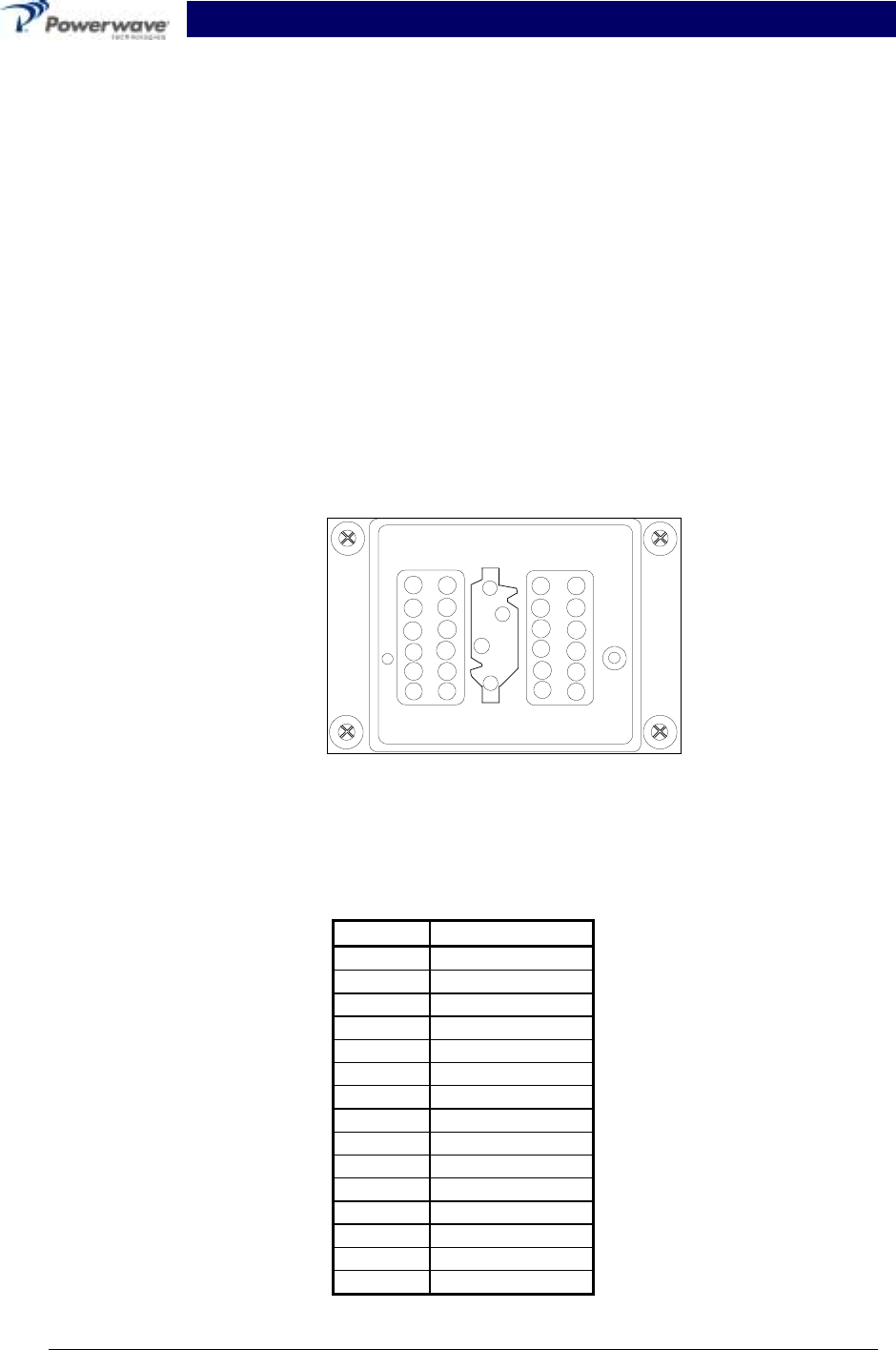
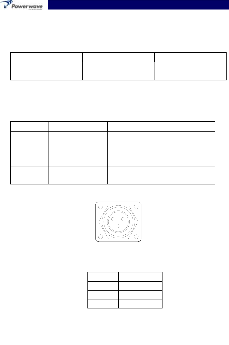
Note: The Connector Identification (A,B and C) is for reference only
and not necessarily labled on the actual connector
Figure 1-1 Masthead Unit Blind mate Connector Interface
Table 1-1 Blindmate Connector Pin Designation
Pin Function
1A +26 VDC
2A +12 VDC
3A -8 VDC
4A COM
5A-12A Not used
1B Not used
2B TX IN
3B TX OUT
4B Not used
1C Mute
2C-4C Not used
5C RS-485H
6C RS-485L
7C COM
8C-12C Not used
1
2
3
4
1
6
1
6
7
12 12
7
AB
C

DRAFT RF Front End System Integration Manual
044-05082 Rev. A 1-3 March 2001
Table 1-2 System Specifications with the MPA9505-55 MCPA
Frequency:
Receive
Transmit 1850-1910 MHz
1930-1945 Mhz
RF Input Power 3dBm (2 milliWatts)
RF Output Power: 55 Watts (47.40 dBm) Max./ 7carriers
Nominal Gain 40 dB ±1.0 dB
Typical Gain Flatness ±0.2 dB (over any 2.0 MHz in band)
Gain Variation Over Temperature 1.0 dB @ -20 to 80 ºC Base Plate
IMD Spurious Emissions @ 7 carriers
(Room Temperature):
Frequency Off-Set ± 885 KHz
Frequency Off-Set ± 1.25 MHz
Frequency Off-Set ± 2.25 MHz
-47 dBc max (30 KHz BW)
-13 dBm max (12.5 KHz BW)
-40 dBc (marker to marker)
IMD Spurious of MCPA in MHU @ An-
tenna Port:
885 KHz, 30 KHz BW
1.98 MHz, 30 KHz BW
2.25 MHz, 1 MHz BW
-47 dBc
-57 dBc
-15 dBm
Spectrum Regrowth of MCPA in MHU @
Antenna Port:
885 KHz
1250 MHz
2250 KHz
-47 dBc
-13 dBm
-13 dBm
Tx Noise in Rx Band @ MCPA Output: -122 dBm/Hz (max.)
Tx Power in Rx Band @ MHUI Rx Output -110 dBm @ Rated Output Power
Input/Output VSWR 1.3 : 1
Output Protection Mismatch Protected
DC Power 27 VDC ± 1.0 VDC @ 24 Amps max.
Sample Port -40 dB ±1.0 dB
Operating Temperature -20 °C to 85 °C Base Plate
Storage Temperature -40 ºC to 85 °C Base Plate
Operating Humidity 0-95% (Non Condensed)
Operating Vibration 1.0 GHz from 10 Hz to 150 Hz
Wind Load 125 mph (min.)
NEMA Rating 4
Remote Alarm Reporting RS-485, Form-C
Receive Band Noise @ MCPA Output -122 dB
Tx-Rx Rejection >75 dB
Dimensions 10(H)x24(W)x48(D) inches
Weight (Fully assembled) 29 lbs (13kg)
DRAFT RF Front End System Integration Manual
044-05082 Rev. A 1-4 March 2001
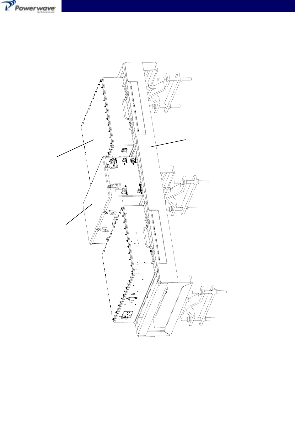
Figure 1-2 The Mast Head Unit with Two Transmit Modules
Transmit
Module
(typ. 2 plcs.)
Common
Box
Mounting
Frame
DRAFT RF Front End System Integration Manual
044-05082 Rev. A 1-5 March 2001
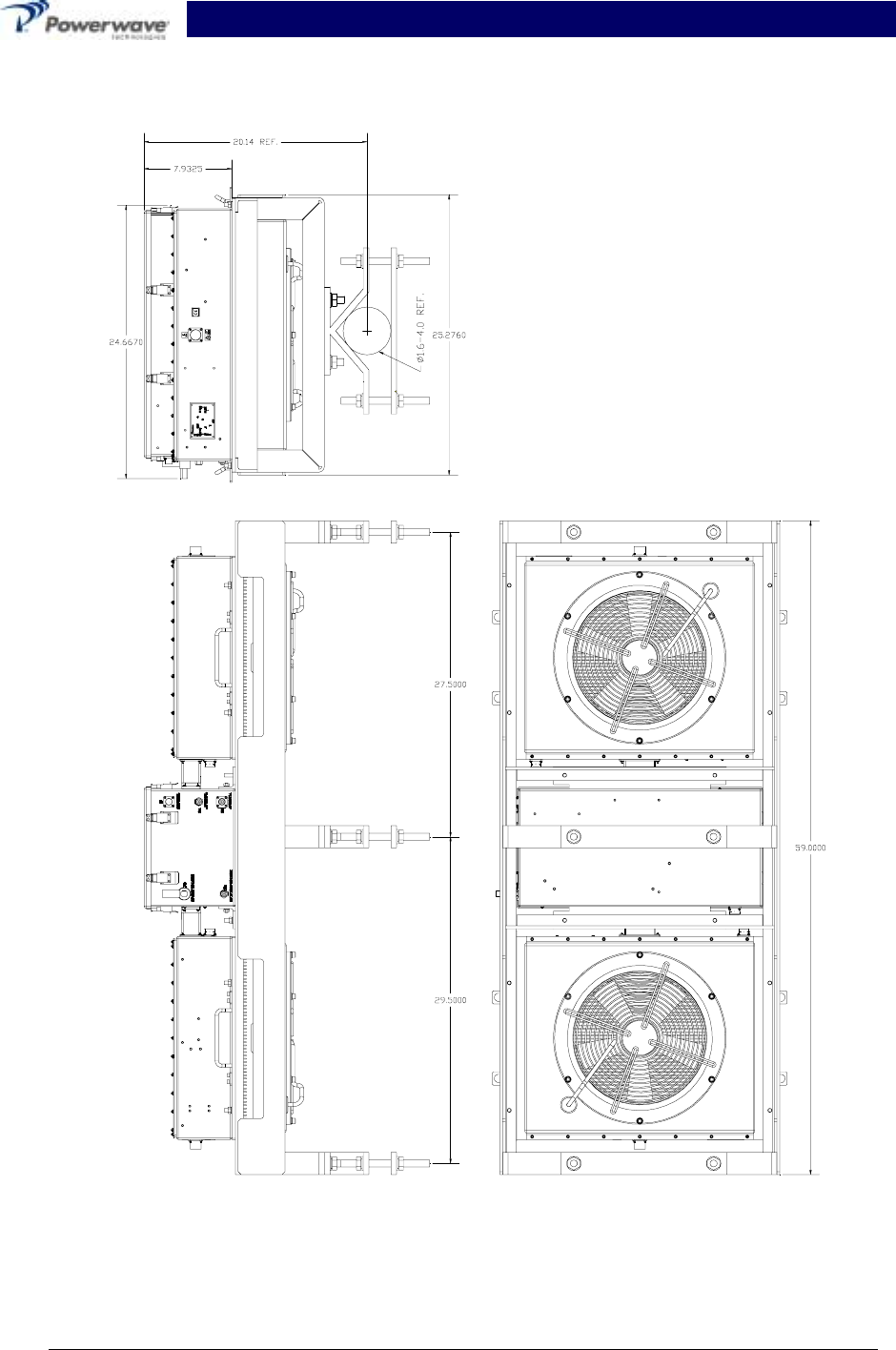
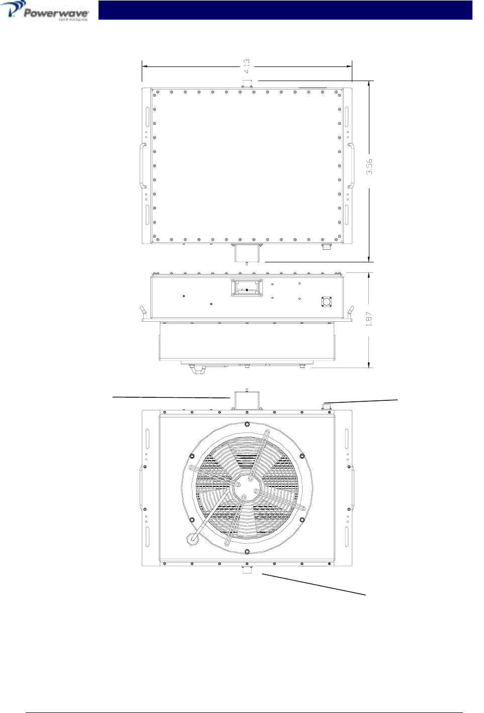
Figure 1-3 Masthead Unit Assembly
DRAFT RF Front End System Integration Manual
044-05082 Rev. A 1-6 March 2001
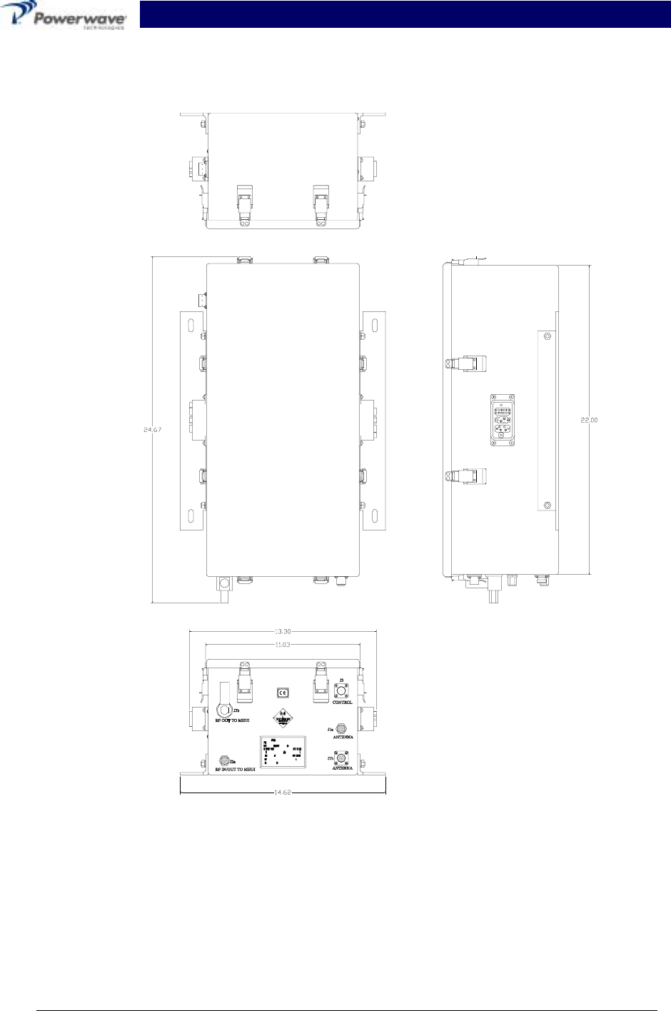
Figure 1-4 The Common Box
Figure 1-5
Figure 1-6 The Common Box Assembly
DRAFT RF Front End System Integration Manual
044-05082 Rev. A 1-7 March 2001
Figure 1-7 The Transmit Module Assembly
220 VAC
Connector
(Typ. 2 Plcs)
Breather
Vent.
(Typ. 2 Plcs)
Blind-mate
Connector
DRAFT RF Front End System Integration Manual
044-05082 Rev. A 1-8 March 2001
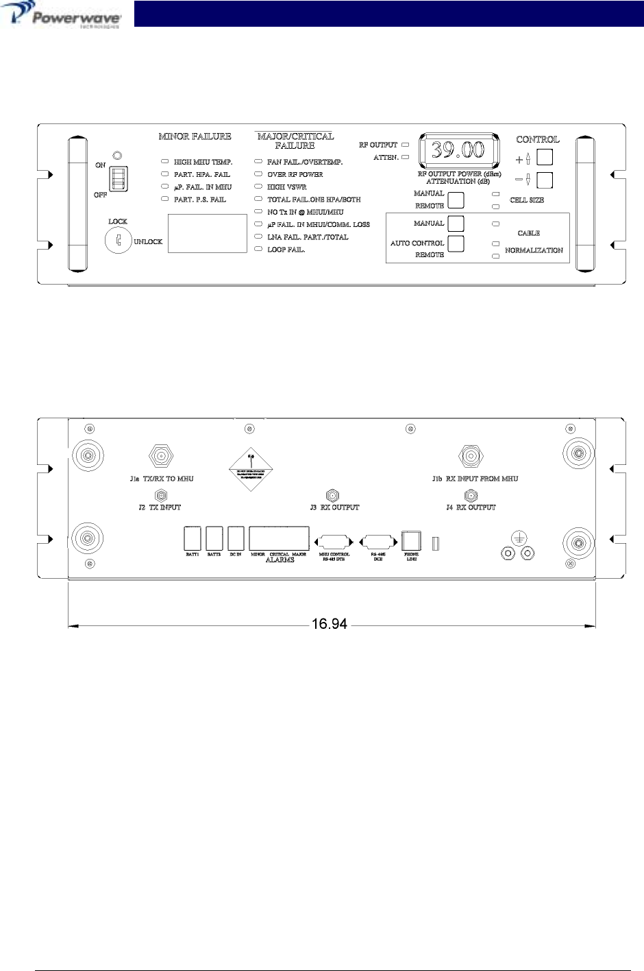
Figure 1-8 Masthead Unit Interface Front and Rear Views.

DRAFT RF Front End System Integration Manual
044-05082 Rev. A 2-1 March 2001
Section 2 Installation Instructions
2-1 Introduction
This section contains unpacking, inspection, installation instructions and recommendations for the
RF Front End (RFFE) System. It is important that the licensee perform the following tasks cor-
rectly and in good faith:
1. Carefully read all material in this section prior to equipment unpacking or installation.
2. Also, read and review the operating procedures in section 3 prior to installing the equipment.
3. If applicable, carefully review the Federal Communications Commission (FCC) rules as they
apply to your installation. DON'T TAKE CHANCES WITH YOUR LICENSE.
2-2 Site Survey
Powerwave Technologies recommends that site surveys be performed by qualified individuals or
firms prior to equipment ordering or installation. Performing a detailed site survey will reduce or
eliminate installation and turn-up delays caused by oversights. A general site survey form is pro-
vided in appendix B. This form is commonly used by Powerwave field engineers and may be
used as a guide. Pay particular attention to power plant capacity, air conditioning needs, RF and
AC/DC cabling/breaker requirements.
2-3 Electrical Service Recommendations
Powerwave recommends that:
• Proper AC line conditioning and surge suppression be provided on the primary AC input to the
+27 VDC power source.
• All electrical service should be installed in accordance with the National Electrical Code, any
applicable state or local codes, and good engineering practice.
• Straight, short ground runs be used.
• The electrical service must be well grounded.
Circuit breakers should be capable of handling the anticipated inrush current, in a load center with
a master switch.
2-4 Air Conditioning
An air-conditioning unit is not required for this Powerwave Equipment.
2-5 Unpacking And Inspection
This equipment (as applicable) has been operated, tested and calibrated at the factory. Carefully
open and remove the Masthead Unit (MHU) components (2 transmit modules, 1 common box and
1 mounting frame assembly with associated mounting hardware) and Masthead Unit Interface
(MHUI) from their respective containers. Retain all packing material that can be reassembled in
the event that the unit must be returned to the factory. Please perform the following steps:
CAUTION
Exercise care in handling equipment during inspection to prevent damage caused by
rough or careless handling.

DRAFT RF Front End System Integration Manual
044-05082 Rev. A 2-2 March 2001
1. Visually inspect the MHU components and the MHUI for damage that may have occurred
during shipment.
2. Check for evidence of water damage, bent or warped chassis, loose screws or nuts, or extra-
neous packing material in the connector(s).
CAUTION
Before applying power, make sure that all connectors to the Units are secure. Make
sure that the input and output of the units are properly terminated at 50 ohms. Do not
operate the system without a load attached. Refer to section 1, table 1-1 for input
power requirements. Excessive input power may damage the equipment.
If possible, inspect the equipment in the presence of the delivery person.
If the equipment is damaged:
• The carrier is your first area of recourse.
• A claim should be filed with the carrier once the extent of any damage is assessed.
We cannot stress too strongly the importance of IMMEDIATE careful inspection of the equipment
and the subsequent IMMEDIATE filing of the necessary claims against the carrier if necessary.
If the equipment is damaged and must be returned to the factory:
• Please write or phone for return authorization. Refer to section 6-3.1 for instructions.
• Powerwave may not accept returns without a return authorization.
Claims for loss or damage may not be withheld from any payment to Powerwave nor may any
payment due be withheld pending the outcome thereof. WE CANNOT GUARANTEE THE
FREIGHT CARRIER'S PERFORMANCE
2-6 Installation Instructions
The RFFE Mast Head Unit (MHU) is designed for installation on the antenna tower. The host
equipment must permit access to the MHU for AC, monitor and RF cables. Proper ventilation is
also required. Powerwave recommends that the MHU be clamped directly to the antenna pole
(see figure 1-3 for mounting frame dimensions). A pole extension may be necessary for some
cell sites. However, if the MHU is mounted to a surface, ensure that there is a minimum clear-
ance of six inches between the mounting surface and the fans to allow for proper air circulation.
The RFFE Mast Head Interface (MHUI) is mounted in the host base station cabinet or rack. The
base station enclosure must permit access to the MHUI for; DC power, RF and monitor cables.
Proceed with the installation instructions as follows:
WARNING
Verify that the ON/OFF switch on the MHUI is in the OFF position. Turn off external
primary AC and DC power before connecting power cables.
1. Install the MHUI into the host base station and secure it into place using #10x32x1/2 Phillips
screws and #10 flat washers.
2. Before assembling the MHU, inspect the blind mate connector on the common box and
transmit modules. Verify that the pins are straight, and that the alignment shield is not bent.
3. Turn off the 220 VAC circuit breaker that feeds the transmit modules.
WARNING
Do not slam the transmit modules into the common box. Forcing the modules into the
housing at too fast a rate may cause inproper connection or damage to the connector.

DRAFT RF Front End System Integration Manual
044-05082 Rev. A 2-3 March 2001
4. Clamp the MHU frame to the antenna tower (see figure 1-4 for frame dimensions).
5. Place the common box into it’s location on the MHU frame (see fiqure 1-1). Secure in place
with the supplied screws.
6. Place a transmit module on the MHU frame. Slide the module toward the common box until it
locks into place with the blind mate connector on the common box. Tightened down with the
supplied screws.
7. Repeat step 5 for the second transmit module.
8. Connect the RF cables to the MHU.
9. Connect the 220 VAC power cable from the host base station’s AC power breaker panel to
the MHU. Refer to figure 2-1 and xx and table 2-1 for pin designations.
10. Connect the TX/RX TO MHU (J1a) on the MHUI to the RF IN/OUT TO MHUI (J2a) port on the
common box.
11. Connect the RX INPUT FROM MHU (J1b) port on the MHUI to the RF OUT TO MHUI (J2b)
port on the MHU.
12. Connect the TX INPUT (J2) port on the MHUI to the TX IN port of the host base station.
13. Connect the RX OUTPUT (J3) on the MHUI to the Rx OUT port of the host base station.
14. Connect the J4 RX OUTPUT on the MHUI to the Rx DIVERSITY OUT on the host base
station.
15. Connect the MHU CONTROL cable on the MHUI to the CONTROL (J3) port on the MHU.
Refer to figures 2-1 and 2-2 and tables 2-2 and 2-5 for pin locations and pin designations.
16. Lift the safety cover on the MHUI DC IN terminal board and connect the dc power cable.
There is no polarity on the terminal board, therefore it doesn’t matter which pin you connect
to. Refer to figure 2-5 and table 2-6. Replace the safety cover.
17. Remove the safety cover from the BATT1 terminal board and connect the host battery back-
up cable. There is no polarity on the terminal board, therefore it doesn’t matter which pin you
connect to. Refer to figure 2-1 and table 2-1. Replace the safety cover.
18. Repeat step 17 for the BATT2 connection.
19. Remove the plastic cover from the alarms terminal board. Connect the alarm cables to their
appropriate terminal. See figure 4-4 for pin locations designation.
WARNING
Check your work before applying AC and DC voltage to the system. Make certain all
connections are tight and correct.
Measure primary DC input voltage. DC input voltage should be +26 VDC ±1.0 Vdc. If the DC in-
put voltage is above or below the limits, call and consult Powerwave before you turn on your am-
plifier system.
Refer to section 3 for initial turn-on and checkout procedures.
DRAFT RF Front End System Integration Manual
044-05082 Rev. A 2-4 March 2001
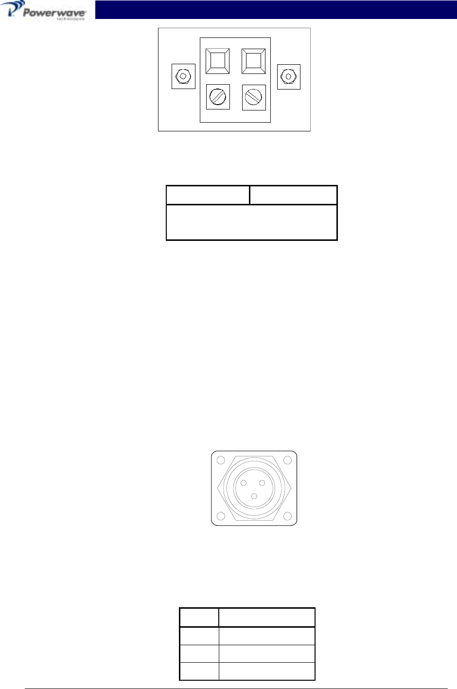
Figure 2-1 DC IN, BATT1, BATT2 Terminal Board Layout
Table 2-1 DC IN, BATT1, BATT2 Terminal Designations
Terminal Point Designation
No Polarity 27VDC
No Polarity 27VDC RTN
2-7 MHU Power, Alarm, Control, and RF Connector
2-7.1 MHU Power
The system 220VAC power is routed to the MHU via the host circuit breaker panel then to the J5
connector on the Tx module (refer to figure 1-5 for the connector location and figure 2-1 and table
2-1 for the connector pin location and designation. The 220VAC is internally routed to the fans
and the module’s rectifier (power supply) circuit that reduces the 220VAC signal to the 27VDC
needed to power the amplifier. The power supply circuit also generates the +12VDC and –8VDC
used to power the MHU internal components.
The amplifier alarm system from the MHU to the MHUI is routed by way of the common box as-
sembly. Connections on the amplifier are made through the blind mate connector. Refer to table
2-3 for a description of the alarms and controls.
Figure 2-2 220VAC Input Connector
Table 2-2 220VAC Pin Designation
Pin Designation
ALine
BLine
C Neutral
CB
A
J5
220VAC IN
DRAFT RF Front End System Integration Manual
044-05082 Rev. A 2-5 March 2001
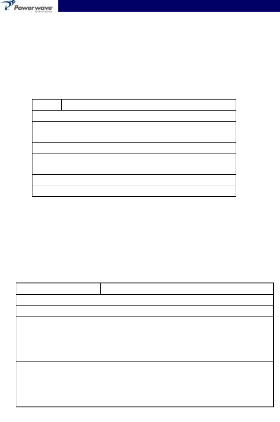
Table 2-3 MCPA Alarms & Controls
Items Specifications Remarks
Alarms & Controls TTL Level; +5 Volts
Buffer: 74ABT244 (5V) - recommended
Deletion Alarm When unit does not exist (HEAR_PAU)
Equipped: GND Deletion OPEN D-Line
Function Fail Alarm When unit does not exist (HEAR_PAU)
Normal: High Abnormal GND D-Line
VSWR Alarm 3:1 (6dB ± 1dB) @ 35dBm-48dBm Output Power. PAU
remains normal operation when this alarm condition
disappears (NOT shutdown)
RS-485
High Temp. Alarm This alarm only at +75ºC. +5
ºC/
/-0
ºC RS-485
Over Power Output
Alarm @output power is greater than +48.5 dBm ±0.5dB.
MCPA will recover when the alarm condition disap-
pears. (NOT shutdown).
RS-485
DC Fail Alarm @ +20.5 Vdc ± 0.5V or +29 Vdc ± 0.5V. When this
alarm occurs the MCPA shall shut-down RS-485
Loop Fail Alarm When an alarm occurs on the feed forward path. RS-485
EN/DISABLE Reserved RS-485
The Alarm Interface connector on the back of the MHUI is a 9-pin female D-sub connector that
permits serial interface with the external alarm monitor. Refer to figure 2-3 and table 2-3 for con-
nector pin definition.
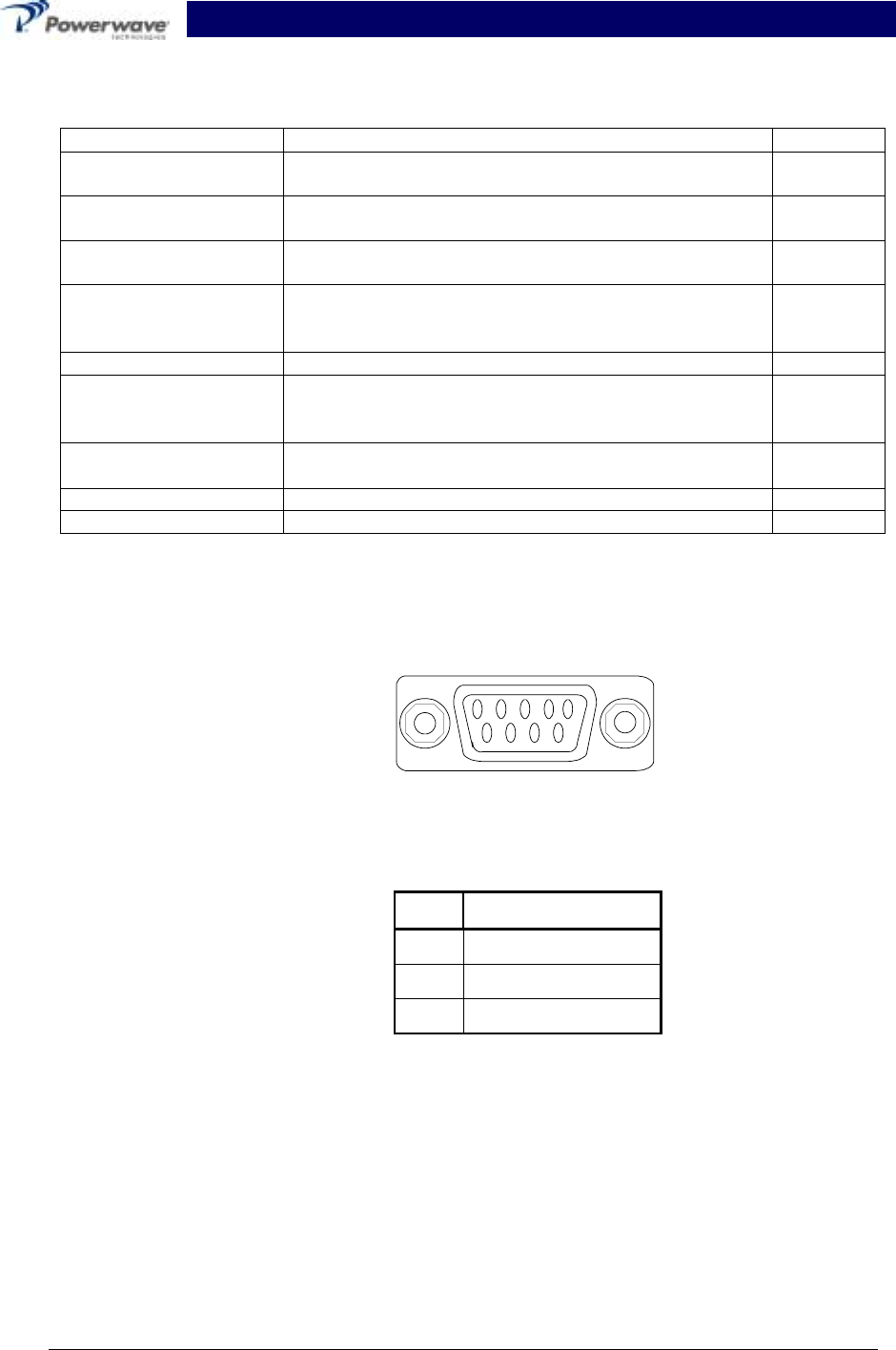
Figure 2-3 MHU Control, RS-485 DTE Connector
Table 2-4 MHU CONTROL Connector Pin Designations
Pin Designation
1 RS-485H
2 RS-485L
3 Common
2-8 Remote Control and Status
2-8.1 RS-485 Physical Layer
The MHUI supports an RS-485 differential serial asynchronous communications link operation at
9600 baud, 1 bit start, 8 bit data, 1 bit parity, 1 bit stop bit, no parity. The MHUI port supports
redundant RS-485 drivers and receivers; the active driver and receiver pair shall be selected by
the state of the supplied RS_485_SEL lines available at the MHUI alarm terminal board. The
MHUI serves Addreses 10h to 13h. The MHUI terminates the RS-485 differential receive and
96
51
DRAFT RF Front End System Integration Manual
044-05082 Rev. A 2-6 March 2001
transmit lines with 120 ohms. Because this communications bus is also shared with other system
resources, the MCPA supports the following asynchronous packet format communications
protocol.
The Low Speed Bus (LSB) 1 and 2 are selected by the following truth table:
Table 2-5 The LSB 1 and LSB 2 Selection Truth Table
LSB RS_485_SEL_H RS_485_SEL_L
110
201
2-8.2 Asynchonous Packet Protocol
The following protocol or similar to support duplex operations of two antennas. The packet format
used for both commands and responses is as follows:
Table 2-6 Asychronous Packet Protocol
Byte Field Description
0 Source ID Address of Source
1 Destination ID Address of Destination
2 CMD/ECHO Command/Echo field
3 LEN Length of transparent binary Data field bytes
4 ADDITIVE CSUM Checksum of all preceding and Data bytes
5 to 4+ LEN Data LEN data bytes for LEN>0, LEN<256
Figure 2-4 J3 CONTROL Connector
Table 2-7 J3 CONTROL Connector Pin Designation
Pin Designation
A RS-485H
B RS-485L
C Common
CB
A
J3
CONTROL

DRAFT RF Front End System Integration Manual
044-05082 Rev. A 2-7 March 2001
2-9 Commands to the MHUI
The CMND/ECHO byte is used to send commands from the host to the MHUI as follow:
Table 2-8 CMND/ECHO comands from the Host to the MHUI
Byte Command
LEN=00H;
CMND/ECHO=
00H Report base status
01H Enable HPA in MHU and report and report base status
02H Disable HPA in MHU and report base status
03H Report extended status
04H Interrogation of temperature in MHU at HPA heat sink
05H Interrogation of RF-output power at MHU HPA output
06H Interrogation of RF-input power at the MHU HPA input
07H Interrogation of RF-input power in the MHUI at TX path after the cell size
attenuator
08H Interrogation of current cable normalization attenuator settings in MHUI
09H Interrogation of current cell cell size attenuator settings in the MHUI
0AH Interrogation of current MHUI attenuator control status for cell size and cable
normalization
0BH Interrogation of (last) manual adjustment value for the cable normalization
0CH Interrogation of (last) manual adjustment value for the cell size attenuator
0DH Switch off remote control of cable normalization attenuators, switch on manual mode
and and report ext. status. The LED for remote control shall be switched off and the
LED for manual controll shall be switched on. Use last stored manual adjustment
value.
0EH Switched off remote control of cable normalization attenuators, switch on automatic
mode and report ext. status. The LED for remote control shall be switched off and
the LED for auto control shall be switched on. Use last stored value calculated by
the automatic control alogorithm.
0FH Switch off remote control of cable normalization attenuators, switch on mode, which
was valid before switching to remote control and report ext. status. The LED for re-
mote control shall be switched off and the LED for automatic control or manual con-
tol shall be switched on. Use last stored manual adjustment value.
10H Switch Cell Size control to manual and report ext. status. Illuminate front panel LED
for manual cell size setting, switch off front panel LED for remote cell size setting.
Use last stored manual adjustment value.
11H Report extended Status and then rest MHUI and MHU. Restart with default settings.
LEN=01H
CMD/ECH=
12H Remote control of cable normalization attenuator: Stop automatic or manual setting
of the attenuator and use fixed value in data byte. Illustratie front panel LED for re-
mote cable normalization. Store current attenuator value for later usage.
13H Remote control of cell size attenuator: Stop manual control of cell size
attenuator use value in data byte. Illuminate front panel LED for remote cell size
setting Store current attenuator value for later usage.
CMD/ECH=
14h-FFH Reserved

DRAFT RF Front End System Integration Manual
044-05082 Rev. A 2-8 March 2001
2-9.1 Responses from the MHUI
The MHUI responses always echo the received CMND byte as the ECHO byte of the response
packet. Amplifier base status is reported by setting the LEN field to 01H and reporting the follow-
ing bit mapped byte in the data field of the response packet for CMD==00h, 01h, 02h base status.
Table 2-9 Bit Mapped Byte in the Data Field fo Response Packet for
CMD==00h, 01h, 02h Base Status
Byte Specification
b0 1=High VSWR shutdown/0=normal
b1 1=High Temperature condition/0=normal
b2 1=Over-temperature shutdown/0=normal
b3 1=Partial Power supply fail at MHU/0=normal
b4 1=Fan fail at MHUI, if fan is implemented/0=normal
b5 1=Over Power shutdown/0=normal
b6 1=Fan ON/0=Fan OFF (if fan is implemented in the MHUI, else 0)
b7 1=Amplifier Enable/0=Amplifier Disabled
NOTE
In case of RF overpower and high VSWR the shutdown condition will be alarmed
only after three unsuccessful attempts of self recovery.
Table 2-10 Bit Mapped Byte in the Data Field for Response Packet for
CMD==03H, 0DH, 0EH, 0FH, 10H or 11H Report Extended Status
Byte Specification
b0 1=partial failure HPA/0=normal
b1 1=partial failure LNA/0=normal
b2 1=total failure HPA/0=normal
b3 1=total failure LNA/0=normal
b4 1=Loss of communication between the MHUI and MHU/0=normal
b5 1=High VSWR warning (>3:1)/0=normal
b6 1=No TX input signal at MHUI/0=normal
b7 1=No TX input signal at MHU/0=normal
For CMD=04…0CH the data field contains the according value with the least significant bit at b0.
Depending on the length not used higher bits are filled with0.
Reply for command 0H4 (data field):
00H= -40 ºC, 1 ºC steps, 88H = +90 ºC
FEH< -40 ºC , FFH > +90 ºC
Reply for commands 05H, 06H and 7H (data field):
00H= -10 dBm, ¼ dB steps, FFH = 53 ¾ dBm
DRAFT RF Front End System Integration Manual
044-05082 Rev. A 2-9 March 2001
Reply for commands 08H, 09H, 0BH and 0CH (data field):
Cell size attenuator:
00H= full attenuation 20dB, FFH= no attenuation 0dB, step size 20/255 dB
Cable normalization attenuator:
00H= full attenuation 20 dB, FFH= no attenuation 0dB, step size 20/255 dB
For commands 12H and 13H the value in the data byte is defined in the same way as above for
cell size and cable normalization respectively.
Table 2-11 MHUI Attenuator Control Status for: CMD==0AH
Byte Specification
b0 1=manual cell size control on/0=normal
b1 1=remote cell size control on/0=normal
b2 0=normal
b3 1=remote manual cable normalization on/0=normal
b4 1=automatic cable normalization algorithm on/0normal
b5 1=remote cable normalization on/0 =normal
b6 0=normal
b7 0=normal
For RF output power, temperature and attenuator values the MHUI shall submitt a rounded value
as long as the exact value is not available.
MHUI responses MUST commence within 50 ms (0.050 sec.) of reception of a valid command
(poll).
2-9.2 Hardware Reset
Reset both MHU and MHUI and restart with default settings. Refer to table 2-12.
Table 2-12 Default Settings
Reset Default Setting
Power Recovery Last known status
Hardware Reset Last known status
Manual Reset by Front Panel
Bottons
Press manual buttons for cell size adjustment, manual
button for cable loss normalization and the button for automatic
control simultaneously
Reset to initial factory preset
Software Reset via RS-485 Last known status
Initial Factory Preset Cell Size Attenuator and Cable loss normalization attenuator at
max. attenuation (20dB for cable normalization attenuator,
20dB for cell size attenuator)
Set front panel display to FFF
No LED is illuminated
DRAFT RF Front End System Integration Manual
044-05082 Rev. A 2-10 March 2001
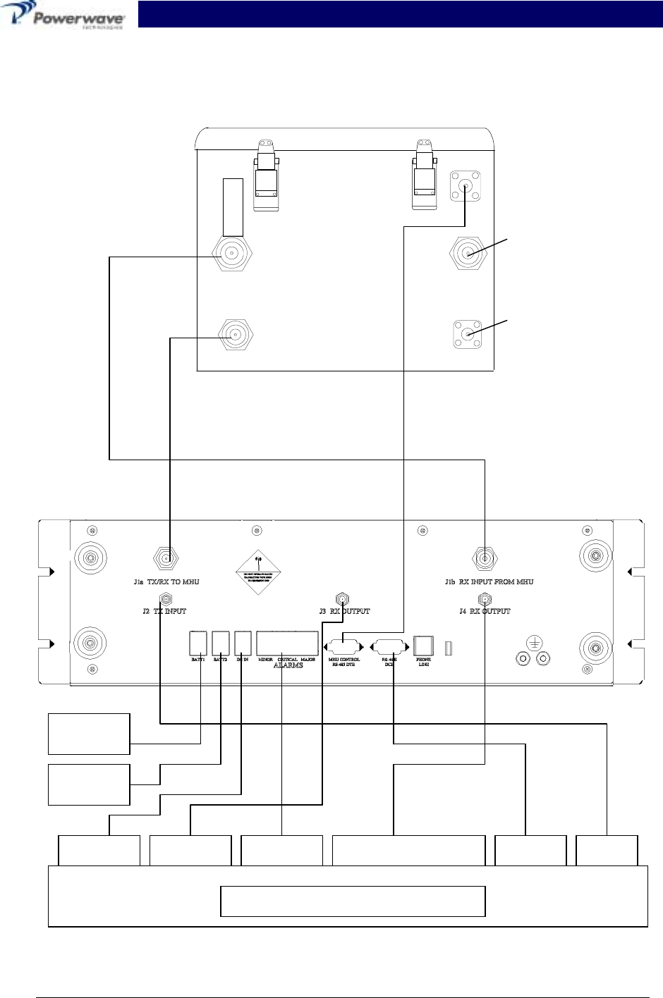
Figure 2-5 System Interconnect Diagram
RF OUT TO MHUI
J2b
J3
CONTROL
J1a
ANTENNA
J1b
ANTENNA
RF IN/OUT TO MHUI
J2a
HOST RADIO BASE STATION
Rx OUT Rx DIVERSITY OUT Tx IN
To Rx/Tx
Antenna
To Rx
Diversity
Antenna
ALARMS RS-485
Battery
Backu
p
1
Battery
Backu
p
2
+27VDC
DRAFT RF Front End System Integration Manual
044-05082 Rev. A 3-1 March 2001
Section 3 Operating Instructions
3-1 Introduction
This section contains operating instructions for Powerwave’s RF Front End system.
3-2 Location and Function of the MHU and MHUI Controls and Indicators
The Masthead Unit (MHU) is not equipped with controls or indicators. Instead, the MHU inter-
faces with the host base station by way of the Masthead Unit Interface (MHUI). The location of
the controls and indicators for the MHUI are shown in figure 3-1. And described in detail below.
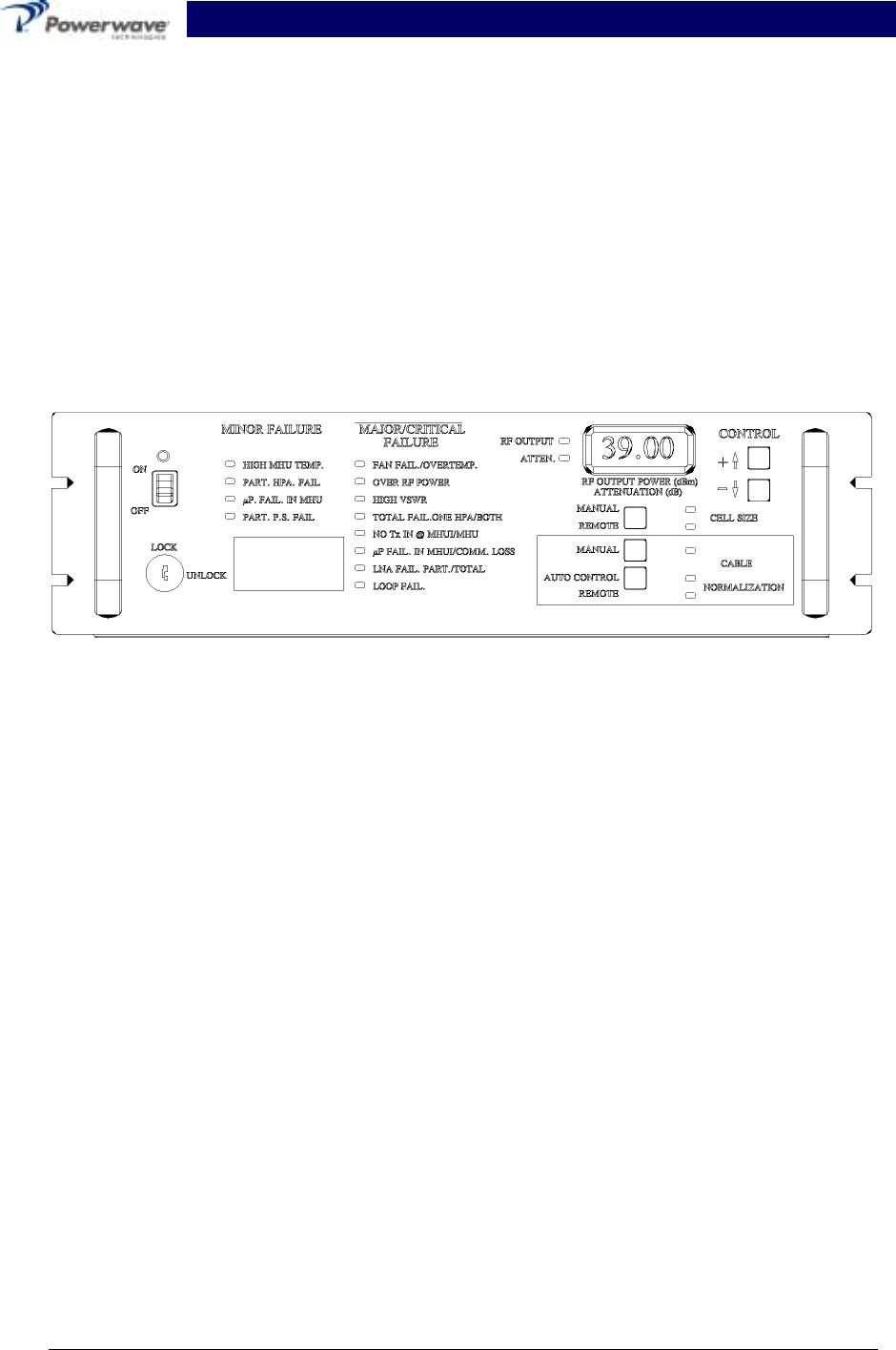
Figure 3-1 MHUI Control Panel
3-2.1 Main Power
The MHUI has a main power switch/circuit breaker and a +24 VDC power indicator (LED) to indi-
cate the power is cycled on the MHUI:
• The MHU amplifier alarm signal enters the amplifier in the DISABLED state and reports the
status as amplifier disabled.
• Except when the service loop shows continuity, in which case the MHU alarm signal will enter
the amplifier in the ENABLED state, unless faults or alarms would prohibit entry to such state.
3-2.2 Enable/Disable of Front Panel Functions
The front panel functions of the MHUI are key protected with the exception of the output power
display, monitoring alarms and main power switch.
3-2.3 MHUI Cell Size Attenuator Settings
The MHUI cell size setting is performed either manually or by remote control. This is indicated by
one of two LEDs illuminated.
At the front of the MHUI a push-button switch is used to enable RF power adjustments for cell
size. If the cell size is controlled by remote and if there is any manual adjustment via the front-
panel, the mode will be manual until a new RS-485 command is received. The attenuator adjust-
ment range is between 0 and 20dB.

DRAFT RF Front End System Integration Manual
044-05082 Rev. A 3-2 March 2001
3-2.4 MHUI Cable-Normaliztion-Attenuators Settings/Cable-Normalization-Mode Selection
Buttons
The MHUI cable normalization attenuator setting is performed either manually or by remote con-
trol or by an automatic control algorithm. This is indicated by one of three LEDs illuminated.
At the front of the MHUI a push-button switch is used to enable the manual setting of the cable
loss normalization attenuators, which are adjusted together with the same push-button switch as
used for manual cell size adjustment.
At the front of the MHUI a push-button switch is used, which enables the automatic control algo-
rithm for cable normalization. If the cable normalization attenuator is being controlled by remote
and if there is any manual adjustment via the front-panel or a manual switch to the automatic
control algorithm, then the mode will be manual or automatic control until a new RS485 command
is received.
If the mode is manual and if the front-panel push-button switch for automatic control is pressed,
the new mode will be automatic control. If the mode is automatic control and if the front-panel
push button for manual adjustment is pressed, the new mode will be manual.
3-2.5 MHUI Alarm Indicators
Front-panel LED’s at the MHUI front-panel will show the alarms of MHU and MHUI. All of these
alarms can be interrogated via RS-485. There are three types of alarms indicated by contact clo-
sures; Minor, Major, and Critical
The alarm types are identified by their associated LED color. They are:
• Minor Alarm (Yellow)
• Major Alarm ( Flashing Red)
• Critical Alarm (Solid Red)
The following table identifies the alarm number and its related function.
Table 3-1 Alarms and Related Function
Alarm Function
1• High temperature condition at the MHU
• Fan fail at MHU
• Over-temperature shutdown at MHU
2•
• Over RF power shutdown
• High VSWR shutdown at antenna port of MHU
3• Partial fail of one MCPA in MHU
• Total fail of one MCPA in MHU
• Total Fail of both MCPA in MHU
4•
• No TX input signal at MHUI
• No TX input signal at MHU
5• Microprocessor in MHU not working
• Microprocessor in MHUI not working
• Loss of communication between MHUI and MHU
6• Partial power supply failure at MHU
• Partial fail of LNA in MHU
• Total fail of LNA in MHU

DRAFT RF Front End System Integration Manual
044-05082 Rev. A 3-3 March 2001
The alarm indicators show the instantaneous condition of the MHU and MHUI.
3-2.5.1 RF overpower
• The MHU-MHUI-system waits 500ms,
• then it will reduce the gain by 3 dB and then
• makes 3 attempts to recover the gain at 500ms intervals without submitting an alarm via
RS485 until (if not successful) it holds the current gain setting and reports an RF overpower
shutdown. The unit will still be transmitting.
3-2.5.2 RF Overpower (with reduced gain)
• The MHU-MHUI-system will wait 500ms until it shuts down.
• Three attempts are made to recover from shutdown at 500ms intervals without submitting an
alarm via RS-485
• If not successful, it makes a final shutdown and reports final status via the RS-485.
3-2.5.3 High VSWR (> 5:1)
• The MHU-MHUI-system will wait 500ms until it shuts down
• Three attempts are made to recover from shutdown at 500ms intervals without submitting an
alarm via RS-485.
• If not successful, it makes a final shutdown and reports final status via the RS-485.
3-2.5.4 Loss of communication between MHU and MHUI (5 seconds without communication)
• The MHUI will switch off the MHU and turn it on later again for resetting the MHU controller.
• If the MHU responds, no alarms have to be submitted via RS-485 but an internal count must
be incremented.
• If this count exceeds 3, an alarm will be submitted via RS-485.
• The MHU will resume at previous status. The incremental count will then return to 0.
• If the MHU does not respond, an alarm will be activated via the RS-485 at the MHUI. The
MHU will then shut itself down.
3-2.6 The Digital Display
A digital display consisting of three seven segment LEDs is used to display the RF output power
of the MHU in dBm.
The display is also used for manual adjustment of the cell size and the cable normalization
attenuators. When the corresponding front panel push-buttons for manual adjustment are
pressed, the current attenuation value in dB is displayed with a minimum resolution of 1dB.
Th same digital display shows temperature in degrees C when a temperature push-button is
pressed. When released, the display reverts to output power.

DRAFT RF Front End System Integration Manual
044-05082 Rev. A 3-4 March 2001
3-3 Initial Start-Up and Operating Procedures
To perform the initial start-up, proceed as follows:
• Double check to ensure that all input and output cables are properly connected.
CAUTION
Before applying power, make sure that the input and output of the amplifiers are prop-
erly terminated at 50 ohms. Do not operate the amplifier without a load attached. Re-
fer to Table 1-1 for input power requirements. Excessive input power may damage
the MCPA.
NOTE
The output coaxial cable between the amplifier and the antenna must be 50 ohm co-
axial cable. Use of any other cable will distort the output.
• Place the power ON/OFF switch on the MHUI front panel in the “ON” position.
• Allow the amplifiers to warm up for at least 5 minutes before taking power readings.
• Refer to Appendix A for the power setting procedure.

DRAFT RF Front End System Integration Manual
044-05082 Rev. A 4-1 March 2001
Section 4 Principles of Operations
4-1 Introduction
This section contains a functional description of the Powerwave RFFE MCPA System. Refer to
figure 4-1 and figure 4-3 for the system and amplifier functional block diagrams respectively.
4-2 RF INPUT Signal
The maximum input power for all carrier frequencies should not exceed the limits specified in sec-
tion 1, table 1-1 of this manual. For proper amplifier loop balance, the out of band components of
the input signals should not exceed -60 dBc. The input VSWR should be 2:1 maximum (or bet-
ter).
4-3 RF OUTPUT Load
The load impedance should be as good as possible (1.5:1 or better) in the working band for good
power transfer to the load. If the amplifier is operated into a filter, it will maintain its distortion
characteristics outside the signal band even if the VSWR is infinite, provided the reflected power
does not exceed one Watt. A parasitic signal of less than one Watt incident on the output will not
cause distortion at a higher level than the normal forward distortion (i.e. -60 dBc).
4-4 System Functional Description
A two unit configuration, the RFFE is comprised of a weatherproof (NEMA 4 rating) outdoor Mast-
head Unit (MHU) booster system and an indoor rack mount Masthead Unit Interface (MHUI). The
MCPA system operates in the PCS frequency range of: 1850MHz to 1910MHz (receive) and
1930MHz to 1945MHz (transmit).
4-4.1 The MHU
The MHU has two solid-state power amplifiers for the transmit signals and low noise amplifiers for
the receive function. Both transmit and receive systems are redundancy protected, and in addi-
tion, there is space diversity provided for the receive system (see figure 1-1). The MHU employs
a common box unit that interfaces the two transmit modules to the MHUI. Signals to and from the
MHU interconnect to the base station transceivers through the indoor MHUI control.
4-4.2 The MHUI
The MHUI is the interface between the MHU system and the host base station. The MHUI reports
alarms via the RS-485 bus or form-C interface (see figures 2-3, 2-4, 4-4 and tables 2-3 and
2-6) and displays alarms using an LED display (see figure 1-1 and 3-1). The MHUI houses a low
power duplexer, control board, the system control panel, a preamp, and the cell size variable at-
tenuators (both transmit and receive).
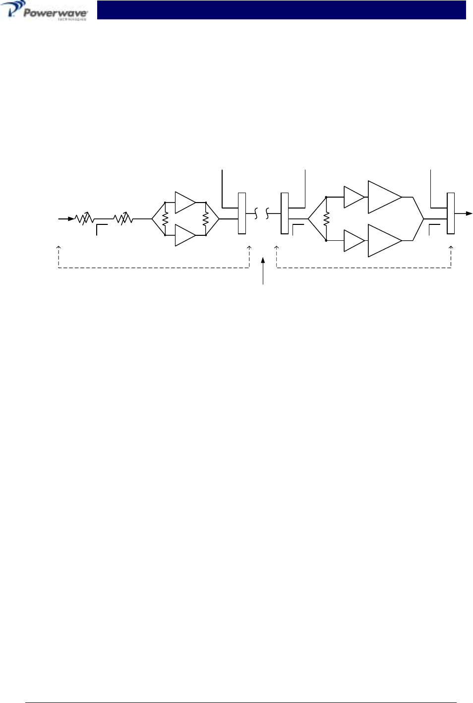
The composite RF signals from the base station radios are applied to the J1a (TX/RX TO MHU)
connector at the rear of the MHUI. From there the signal passes through a combiner a voltage
variable attenuator (VVA) for cell size setting, a second attenuator for cable loss normalization a
diplexer, a third VVA for cable loss normalization, then out through a two-way splitter. Each leg of
the splitter passes through an isolator, then the blind-mate connector to interface with the MCPA.
The signal returns to the MHUI via the blind-mate connector after being amplified by the MCPA
modules. The active power combiner combines the two high-power signals. The active power
combiner has the capability of switching MCPA channels off-line by the use of RF switches. If an
MCPA is not present, turned off, or faulted, the switch will open in that channel and physically dis-
connect that MCPA. The combiner maintains its low insertion characteristics when used in the
DRAFT RF Front End System Integration Manual
044-05082 Rev. A 4-2 March 2001
single path configuration. Note that the splitter is not switched, therefore the power is automati-
cally reduced by 3 dB, thus eliminating an output overdrive condition. The output of the combiner
is fed through a coupler, then a receive-band filter. The amplified RF signal is available for use at
the output of the receive-band filter (J2). The coupler is used to sample the output power to the
true RMS detector. The true RMS detector will supply the micro controller with an accurate aver-
age power regardless of the signal modulation type. The dynamic range is 25 dB. The power
reading is used during the gain initialization phase when deploying the system or monitoring to
detect excessive output power. In both cases the VVA will be adjusted accordingly.
Figure 4-1 RF Front End System Functional Block Diagram
4-4.3 Transmit Modules
Power output specifications for a two module system is listed in section 1, table 1-1. Each module
houses an MPA9505-55 MCPA and one 27VDC 1200 Watt power supply. It is a self-contained
plug-in unit and is functionally independent of the other transmit module. The transmit modules
are designed for parallel operation to achieve high peak power output, and for redundancy in un-
manned remote locations.
4-4.3.1 MPA9505-55 MCPA
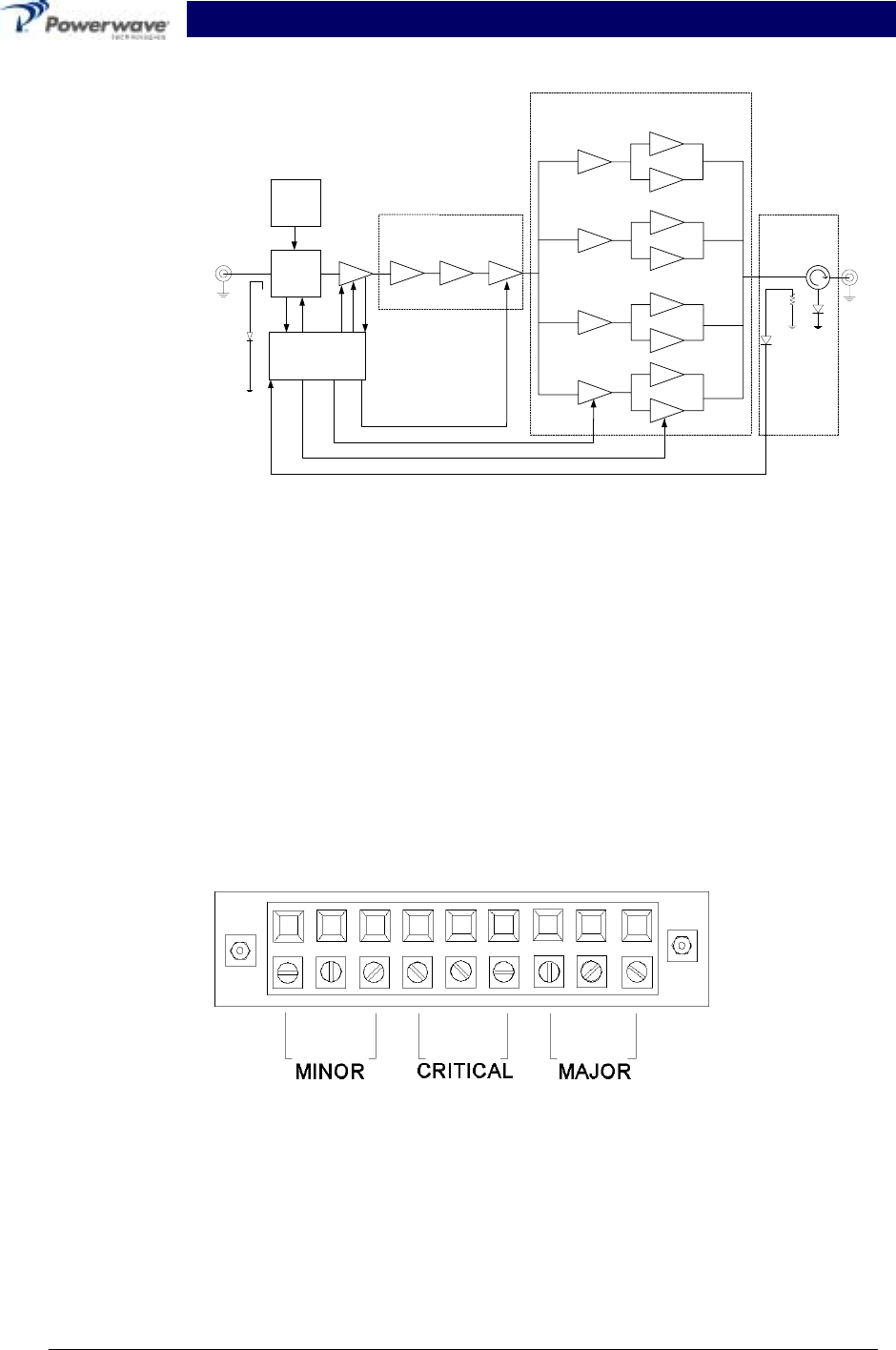
The MCPA is an AB amplifier that utilizes pre-distortion technology for linearization. The pre-
distortion technique is effective because it compensates for the non-linear amplification charac-
teristics of the power amplifier. The amplifier module, figure 1-6, has an average power output of
55 Watts maximum with intermodulation products suppressed to better than -40 dBc (at ±2.25
MHz from Fc) below carrier levels. The amplifier provides an amplified output signal with constant
gain and phase by adding approximately 30 dB of distortion cancellation on the output signal.
Constant gain and phase is maintained by continuously comparing active paths with passive ref-
erences, and correcting for small variations through the RF feedback controls (refer to figure 4-3
for the amplifier’s functional block diagram). All gain and phase variations, for example those due
to temperature, are reduced to the passive reference variations
Cable
DiplexerDiplexer
Dr.
Dr.
PD
PD
HPA
HPA
VVA Box
MHUMHUI
Diplexer
Cable run from
base station to
masthead
RX Path RX Path RX Path
DRAFT RF Front End System Integration Manual
044-05082 Rev. A 4-3 March 2001
Figure 4-2 MPA9505-55 MCPA Functional Block Diagram
4-4.4 Power Distribution
Primary AC and DC power for the RFFE system is provided by the host system. Each Tx module
on the MHU has its own +27VDC power supply, powered by 220VAC from the host circuit breaker
panel. The Tx power supply also produces the ±20VDC, +12VDC, and -8VDC for the systems
internal components.
4-4.5 Alarms
The presence of the two plug-in amplifier alarms can be detected at the ALARMS terminal board
at the rear of the MHUI control panel. Refer to figure 4-3 for a description of the connector and
pin designations.
Figure 4-3 Form C Dry Contacts Alarms Terminal Board
4-4.6 Amplifier Module Cooling``
To maintain operating temperature, each transmit module is equipped with its own heat sink and
220 VAC cooling fan. Mounted at the back of the module (see figure 1-7), the fan forces outside
air onto the enclosure housing. The fans are field replaceable. Refer to section 5 for replacement
procedure.
SAMPLE
-30dB
RF-IN RF-OUT
VSWR
30W.125W
Driver Section
Main Section
Combiner
Section
uProcessor
BLF2047s
BLF2045s
2WPRE-D
MULTIFUNCTION
BOARD
SYSTEM
DRIVER
(35dB)
BLF2047s
BLF2047s
BLF2045s
BLF2047s
BLF2047s
BLF2045s
BLF2047s
BLF2047s
BLF2045s
BLF2047s
VG3
VG2
VG1
OUTPUT DETECTOR
GAIN
PHASE
AGC
MRF284

DRAFT RF Front End System Integration Manual
044-05082 Rev. A 5-1 March 2001
Section 5 Maintenance
5-1 Introduction
This section contains periodic maintenance and performance test procedures for the RF Front
End (RFFE). It also contains a list of test equipment required to perform the identified tasks.
NOTE
Check your sales order and equipment warranty before attempting to service or repair
the unit. Do not break the seals on the equipment under warranty or the warranty will
be null and void. Do not return equipment for warranty or repair service until proper
shipping instructions are received from the factory.
5-2 Periodic Maintenance
Periodic maintenance requirements are listed in table 5-1. Table 5-1 also lists the intervals at
which the tasks should be performed.
WARNING
Wear proper eye protection to avoid eye injury when using compressed air.
Table 5-1 Periodic Maintenance
Task Interval Action
Cleaning:
Air Vents 30 Days Inspect and clean per para. 5-4.
Inspection:
Cables and
Connectors 12 Months Inspect signal and power cables for
frayed insulation. Check RF con-
nectors to be sure that they are
tight.
Performance Tests: 12 Months Perform annual test per para. 5-5.
5-3 Test Equipment Required For Test
NOTE
All RF test equipment must be calibrated to 0.05 dB resolution. Any deviation from
the nominal attenuation must be accounted for and factored into all output readings.

DRAFT RF Front End System Integration Manual
044-05082 Rev. A 5-2 March 2001
Table 5-2 Test Equipment Required
Nomenclature Manufacturer Model
5-4 Clean Air Inlets/Outlets
The air inlets and outlets should be cleaned every 30 days. If the equipment is operated in a se-
vere dust environment, they should be cleaned more often as necessary. Turn off DC power
source before removing fans. If dust and dirt are allowed to accumulate, the cooling efficiency
may be diminished. Using either compressed air or a brush with soft bristles, loosen and remove
accumulated dust and dirt from the air inlet panels.
5-5 Performance Test
Performance testing should be conducted every 12 months to ensure that the amplifier system
meets the operational specifications listed in table 5-3. Also verify system performance after any
amplifier module is replaced in the field. The test equipment required to perform the testing is
listed in table 5-2, and the test setup is shown in figure 5-1.
NOTE
The frequencies used in this test are typical for an amplifier with a 15 MHz band from
1930 MHz to 1945 MHz. Select evenly spaced F1, F2, F3, and F4 frequencies that
cover the instantaneous bandwidth of your system.

DRAFT RF Front End System Integration Manual
044-05082 Rev. A 5-3 March 2001
5-6 Field Replaceable Parts and Modules
The following parts and modules can be replaced in the field on site by a qualified technician with
experience maintaining RF power amplifiers and similar equipment:
• Transmit Modules
• Cooling Fans
5-6.1 Replacing a Transmit Module
The To replace a power amplifier module, proceed as follows:
1. Turn off the 220 VAC circuit breaker that feeds the MHU
2. Loosen the four screws that secure the amplifier module to the MHU chassis.
3. Carefully slide the amplifier away from the common box.
4. Install the replacement amplifier in reverse order.
CAUTION
To avoid damage to the module and blindmate connector, care must be taken as not
to drop the module when removing it from the MHU support frame. The amplifier
weighs approximately 10 lbs.
5-6.2 Replacing the Cooling Fans
5-6.2.1 To replace a front cooling fan, proceed as follows:
1. Turn off the 220 VAC power to the MHU.
2. Unplug the power line to the fan.
3. Remove the six screws holding the fan to its chassis (you may be required to remove the
MHU from the mounting pole to gain access to the fan.
4. Pull fan out.
5. Install the replacement fan in reverse order of steps 1, 2, 3 and 4 above.

RF Front End System Integration Manual
044-05082 Rev. A 6-1 March 2001
Section 6 Troubleshooting
6-1 Introduction
This section contains a list of problems which users have encountered and a few suggested ac-
tions that may correct the problem. If the suggested corrective action does not eliminate the
problem, please contact your Powerwave field representative or the factory for further instructions.
Note
Check your sales order and equipment warranty before attempting to service or repair
the unit. Do not break the seals on equipment under warranty or the warranty will be
null and void. Do not return equipment for warranty or repair service until proper
shipping instructions are received from the factory.
6-2 Troubleshooting
Refer to table 6-1 for troubleshooting suggestions.
Table 6-1 Troubleshooting
Symptom Suggested Action
The voltage indicator (green)
is not lit or blinking
1. Check that the MHU-MHUI power connectors are secure.
2. Check for proper power supply voltage.
High Temp alarm LED is lit 1. Verify fan(s) are operating properly.
2. Check ambient temperature (not to exceed spec. See
table 1-1).
Over Pwr alarm LED is lit Verify RF input level does not exceed spec. See table 1-1.
VSWR alarm LED is lit Check output connections and cables for integrity and
tightness.
6-3 Return For Service Procedures
When returning products to Powerwave, the following procedures will ensure optimum response.
6-3.1 Obtaining an RMA
A Return Material Authorization (RMA) number must be obtained prior to returning equipment to
the factory for service. Please contact our Repair Department at (714) 466-1000 to obtain this
number, or FAX your request to (714) 466-5800. Failure to obtain this RMA number may result in
delays in receiving repair service.
6-3.2 Repackaging for Shipment
To ensure safe shipment of the amplifier, it is recommended that the package designed for the
amplifier is used. The original packaging material is reusable. If it is not available, contact our
Repair Department for packing materials and information.