Powerwave Technologies 5JS0058 Multi-Carrier Power Amplifier User Manual I GENERAL DESCRIPTION
Powerwave Technologies Inc Multi-Carrier Power Amplifier I GENERAL DESCRIPTION
User Manual

869-894 MHz
Copyright Powerwave Technologies, Inc., April 2002. All rights reserved
044-05112 Rev. A April 2002
Multi-Carrier Power Amplifier
869 – 894 MHz
G3S-800-180-29
Installation & Service Manual
180 Watts Average Power (210 W Max.)
-60 dBc Intermodulation Distortion

G3S-800-180-029 Installation & Service Manual
Copyright Powerwave Technologies, Inc., April 2002. All rights reserved
044-05112 Rev. A ii April 2002
April 2002
Powerwave Technologies, Inc. Tel: (714) 466-1000
1801 East St. Andrew Place (888) 797-9283
Santa Ana, CA 92705 Fax: (714) 466-5800
Web Site: www.powerwave.com
© 2002 Powerwave Technologies Incorporated. All rights reserved.
Powerwave Technologies, and the Powerwave logo are registered trademarks
Powerwave Technologies, Inc. reserves the right to make changes to the documentation and
equipment, including but not limited to component substitution and circuitry changes. Changes
that impact this manual may subsequently be incorporated in a later revision of this manual.

G3S-800-180-029 Installation & Service Manual
Copyright Powerwave Technologies, Inc., April 2002. All rights reserved
044-05112 Rev. A iii April 2002
Table Of Contents
Par. Section 1 Page
No. General Description No.
1-1 Introduction..........................................................................................................................................................1-1
1-2 General Description..........................................................................................................................................1-1
1-3 Functional And Physical Specifications.......................................................................................................1-1
1-4 Equipment Changes............................................................................................................................................1-1
1-5 Ordering Information.......................................................................................................................................... 1-2
Section 2
Installation
2-1 Introduction..........................................................................................................................................................2-1
2-2 Electrical Service Recommendations............................................................................................................ 2-1
2-3 Air Conditioning..................................................................................................................................................2-2
2-4 Unpacking and Inspection................................................................................................................................ 2-2
2-5 Installation Instructions....................................................................................................................................2-3
2-6 Amplifier Module Connectors.......................................................................................................................... 2-4
2-6.1 Amplifier Module Status, Alarm, Control, and Power Connector............................................................ 2-4
2-6.2 Amplifier Module RF Connector...................................................................................................................... 2-5
Section 3
Operating Instructions
3-1 Introduction..........................................................................................................................................................3-1
3-2 Location and Function of Amplifier Module Controls and Indicators..................................................... 3-1
3-2.1 Voltage Indicators and On/Off /Reset Switch............................................................................................... 3-1
3-2.1.1 On Off Switch.......................................................................................................................................................3-1
3-2.1.2 RF On Switch.......................................................................................................................................................3-1
3-2.1.3 +27VDC Indicator................................................................................................................................................3-2
3-2.1.4 +15VDC Indicator................................................................................................................................................3-2
3-2.1.5 +5VDC Indicator..................................................................................................................................................3-2
3-2.1.6 -5VDC Indicator................................................................................................................................................... 3-2
3-2.2 Alarm Indicators.................................................................................................................................................3-2
3-3 Initial Start-Up and Operating Procedures...................................................................................................3-4
Section 4
Principles of Operation
4-1 Introduction..........................................................................................................................................................4-1
4-2 RF Input Signal ....................................................................................................................................................4-1
4-3 RF Output Load..................................................................................................................................................... 4-1
4-4 G3S-800-180-029 Amplifier Module................................................................................................................4-1
4-4.1 Main Amplifier.................................................................................................................................................... 4-2
4-4.2 Error Amplifier.....................................................................................................................................................4-2
4-4.3 Amplifier Monitoring.........................................................................................................................................4-2
4-4.4 Amplifier Module Cooling ................................................................................................................................4-3
4-5 Power Distribution.............................................................................................................................................4-3
4-6 Intermodulation...................................................................................................................................................4-3
4-7 Alarms...................................................................................................................................................................4-3

G3S-800-180-029 Installation & Service Manual
Copyright Powerwave Technologies, Inc., April 2002. All rights reserved
044-05112 Rev. A iv April 2002
Section 5
Maintenance
5-1 Introduction..........................................................................................................................................................5-1
5-2 Periodic Maintenance....................................................................................................................................... 5-1
5-3 Test Equipment Required For Test..................................................................................................................5-1
5-4 Clean Air Inlets/Outlets.....................................................................................................................................5-2
5-5 Performance Test ...............................................................................................................................................5-2
5-5.1 Amplifier System Performance Test...............................................................................................................5-2
5-5.1.1 Amplifier IMD Test..............................................................................................................................................5.3
5-5.1.2 Gain Test...............................................................................................................................................................5-3
5-5.1.3 Harmonic Test..................................................................................................................................................... 5-3
5-5.1.4 Spurious Emissions Test................................................................................................................................... 5-4
5-5.1.5 Input Return Loss................................................................................................................................................5-4
5-6 Field Replacement Parts and Modules.......................................................................................................... 5-5
5-6.1 G3S-800-180-029 Power Amplifier Module...................................................................................................5-5
5-6.2 Cooling Fans ........................................................................................................................................................5-6
Section 6
Troubleshooting
6-1 Introduction.......................................................................................................................................................... 6-1
6-2 Troubleshooting.................................................................................................................................................. 6-1
6-2.1 DC Voltage Indicators Not Illuminated..........................................................................................................6-1
6-2.2 OVER PWR Illuminated or Blinking................................................................................................................6-1
6-2.3 HIGH TEMP Illuminated ....................................................................................................................................6-2
6-2.4 VSWR Illuminated..............................................................................................................................................6-2
6-2.5 DC FAIL Illuminated............................................................................................................................................ 6-3
6-2.6 FAN FAIL Illuminated.........................................................................................................................................6-3
6-2.7 LOOP FAIL Illuminated....................................................................................................................................... 6-3
6-2.8 LOW PWR Illuminated....................................................................................................................................... 6-3
6-2.9 LPA DISABLE Illumunated................................................................................................................................ 6-3
6-3 Return for Service Procedures ........................................................................................................................6-4
6-3.1 Obtaining an RMA ..............................................................................................................................................6-4
6-3.2 Repackaging for Shipment...............................................................................................................................6-4
List of Illustrations
Figure
No.
1-1 G3S-800-180-029 Front and Side View...........................................................................................................1-3
2-1 G3S-800-180-029 Rear View.............................................................................................................................2-4
2-2 DC and Logic Connector.................................................................................................................................... 2-4
2-3 Amplifier RF Connector.....................................................................................................................................2-5
3-1 G3S-800-180-029 Amplifier Module RF Control Indicators........................................................................3-1
4-1 G3S-800-180-029 Power Amplifier Module Functional Block Diagram ................................................. 4-2
5-1 Amplifier System Test Setup Diagram........................................................................................................... 5-3
5-2 Amplifier Spring Clip Location........................................................................................................................ 5-5

G3S-800-180-029 Installation & Service Manual
Copyright Powerwave Technologies, Inc., April 2002. All rights reserved
044-05112 Rev. A vApril 2002
List Of Tables
Table
No.
1-1 Major Amplifier Components...........................................................................................................................1-2
1-2 G3S-800-180-029 MCPA Functional Specifications ....................................................................................1-2
2-1 Sample of DC Cable Ratings.............................................................................................................................2-1
2-2 Averaged DC Current Load ...............................................................................................................................2-2
2-3 Averaged Heat Loading..................................................................................................................................... 2-3
2-4 Amplifier Module DC and Logic Connector Definition............................................................................... 2-5
2-5 Amplifier RF Connector Definition..................................................................................................................2-4
3-2 Amplifier Module Alarm Indicators Definition............................................................................................3-3
5-1 Periodic Maintenance....................................................................................................................................... 5-1
5-2 Test Equipment Required.................................................................................................................................. 5-2
5-3 MCPA Test Data Sheet......................................................................................................................................5-5

G3S-800-180-029 Installation & Service Manual
Copyright Powerwave Technologies, Inc., April 2002. All rights reserved
All specifications are subject to change without notice. Contact the factory for complete performance data.
044-05112 Rev. A 1-1 April 2002
Section 1 General Description
1-1 Introduction
This manual contains information and procedures for installation, operation, and maintenance of
Powerwave’s G3S-800-180-029 multicarrier cellular amplifier. The manual is organized into six
sections as follows:
Section 1. General Description
Section 2. Installation
Section 3. Operating Instructions
Section 4. Principles of Operation
Section 5. Maintenance
Section 6. Troubleshooting
1-2 General Description
The G3S-800-180-029 (see figure 1-1) is a linear, feed-forward power amplifier that operates in
the 25 MHz frequency band from 869 MHz to 894 MHz. The amplifier can simultaneously transmit
multiple frequencies, with better than -60 dBc third order intermodulation distortion (IMD). It is de-
signed for use in an amplifier system that is modular in design, and is ideally suited for use in
AMPS/TDMA/CDMA/CDPD/W-CDMA base stations. The plug-in Model G3S-800-180-029 ampli-
fier modules can each provide 180 watts of power nominally (210 W max.) and function com-
pletely independently of each other. The amplifier modules are designed for parallel operation to
produce high peak power output and system redundancy for remote applications, when installed
in multi-module amplifier subracks manufactured by Powerwave. All solid-state, the system is de-
signed to provide trouble-free operation with minimum maintenance. The system's modular con-
struction and unique and highly effective LED-based operational status and fault indicators help
minimize downtime. The turn-on and turn-off sequences of voltages are fully automatic, as is
overload protection and recycling. Inadvertent operator damage from front panel manipulation is
virtually impossible.
The amplifier module has a status connector that allows the host system to monitor the amplifier
module’s status. The front panel of each amplifier module has unit level status/fault indicators and
an RF on/off/reset switch. Primary power for the amplifier is +27 Vdc. Cooling for each plug-in
amplifier module is provided by four fans, two mounted on the front and two on the rear of the
module. The fans draw outside air through the front of the module and exhaust hot air out
through the rear of the module.
1-3 Functional And Physical Specifications
Functional and physical specifications for the amplifier are listed in table 1-2.
1-4 Equipment Changes
Powerwave Technologies, Inc. reserves the right to make minor changes to the equipment, in-
cluding but not necessarily limited to component substitution and circuitry changes. Changes that
impact this manual may subsequently be incorporated in a later revision of this manual.
G3S-800-180-029 Installation & Service Manual
Copyright Powerwave Technologies, Inc., April 2002. All rights reserved
All specifications are subject to change without notice. Contact the factory for complete performance data.
044-05112 Rev. A 1-2 April 2002
1-5 Ordering Information
Table 1-1 following gives the part numbers and descriptions to be used when ordering either an
entire amplifier or replacement fans.
Table 1-1 Major Amplifier Components
Model Number Description
G3S-800-180-029 180 W 869-894 MHz MCPA Module
800-01075-003 Front fan assembly
800-00972-002 Rear fan assembly.
Table 1-2 G3S-800-180-029 Multicarrier Cellular Amplifier Functional Specifications
Frequency Range 869-894 MHz (25 MHz Bandwidth)
Instantaneous Bandwidth 25 MHz
Total Typical / Maximum Input Power -5.44 / -5.0 dBm
Total Output Power 180 W (52.55 dBm) Nominal, 210 W (53.22 dBm) Max.
(1 Module)
IMD and In-band Spurious, mean
measurement, 30 KHz bandwidth@
+26 to +28Vdc, 25°C
-60 dBc or -16 dBm max @ up to 16 equal power CW
tones with a combined maximum power of P0 with a
max single carrier power of P0/16.
Out of Band Spurious & Noise,
measured in 30 KHz BW -60 dBc max @ +26 to +28 Vdc
RF Gain 58 dB +0.5 dB
Gain Flatness: ±0.5 dB @ 27 Vdc ±1 Vdc
Gain Variation w/ Voltage and
Frequency + 0.5 dB; 26 to 28 Vdc
Gain Variation Over Temperature: ±0.5 dB
Noise Figure 28 dB max
Output Protection: Mismatch Protected
Input Port Return Loss: 16 dB min
Harmonics: Better than -50 dBc
Out of Band Spurious: Better than -60 dBc
Duty Cycle: Continuous
DC Input Power: +27 Vdc ±1 Vdc, 62 amps typical (70 amps max)
Operational +21.7 Vdc to 30 Vdc (Po derated outside
normal operating range)
DC Circuit Breaker Rating 100 Amps
Operating Temperature: 0 ºC to +40 ºC
Storage Temperature: -40 ºC to +85 ºC
Operating Humidity: 0 % to 80 % Relative Humidity (noncondensing)
Storage Humidity: 0 % to 100 % Relative Humidity (noncondensing)
DC Input, Summary Alarm, and RF
Input / Output Connectors: 21-Pin D-Subminiature Combo Connector plus single-
pin D-Sub connector for additional DC capability.
Heat Generation 4852 BTUs @ 26 VDC, Po = 180 W (1 Amplifier)
Weight 50 lbs.
Dimensions: 5.20” High, 17.00” Wide, 20.00” Deep
Electrical Service Recommendations
Circuit Breakers Capable of handling anticipated inrush current (nor-
mally 25% over equipment maximum current draw), in
a load center with a master switch.
G3S-800-180-029 Installation & Service Manual
Copyright Powerwave Technologies, Inc., April 2002. All rights reserved
All specifications are subject to change without notice. Contact the factory for complete performance data.
044-05112 Rev. A 1-3 April 2002
Figure 1-1 G3S-800-180-029
G3S-800-180-029 Installation & Service Manual
Copyright Powerwave Technologies, Inc., April 2002. All rights reserved
044-05112 Rev. A 2-1 April 2002
Section 2 Installation
2-1 Introduction
This section contains installation recommendations, unpacking, inspection, and installation in-
structions for the Multicarrier Cellular Amplifier. Carefully read all material in this section prior to
equipment unpacking or installation. Also read and review the operating procedures in Section 3
prior to installing the equipment. It is important that the licensee perform these tasks correctly and
in good faith. If applicable, carefully review the Federal Communications Commission (FCC) rules
as they apply to your installation. DON'T TAKE CHANCES WITH YOUR LICENSE.
2-2 Electrical Service Recommendations
Powerwave Technologies recommends that proper AC line conditioning and surge suppression
be provided on the primary AC input to the +27 Vdc power source. All electrical service should be
installed in accordance with the National Electrical Code, any applicable state or local codes, and
good engineering practice. Special consideration should be given to lightning protection of all
systems in view of the vulnerability of most transmitter sites to lightning. Lightning arrestors are
recommended in the service entrance. Straight, short ground runs are recommended. The elec-
trical service must be well grounded.
Each amplifier system should have its own circuit breaker, so a failure in one does not shut off the
whole installation. Circuit breakers should be capable of handling the anticipated inrush current, in
a load center with a master switch. Powerwave recommends that a 100 amp circuit breaker be
installed in the power distribution unit for each amplifier. DC wire smaller than 2 AWG 90°C cop-
per DC should not be installed. Each amplifier should have its own DC cable pair. See table 2-1.
CAUTION
This table and the foregoing are provided as guidelines. Follow the appropriate NEC
standards in your area and the cable manufacturer’s recommendation for proper cable
selection.
Table 2-1 Sample of DC Cable Ratings
AWG Copper Aluminum
or 3 Cond. In Raceway Single Conductor In Free Air 3 Cond. In Raceway Single Conductor In Free Air
MCM 90°C 110°C90°C 110°C 125°C 200°C90°C 110°C90°C 110°C 125°C 200°C
14 25 30 30 40 40 45 -- -- -- -- -- --
12 30 35 40 50 50 55 25 25 30 40 40 45
10 40 45 55 65 70 75 30 35 45 50 55 60
8 55 60 75 85 90 100 40 45 55 65 70 80
6 70 80 100 120 125 135 55 60 80 95 100 105
4 95 105 135 160 170 180 75 80 105 125 135 140
2 125 135 185 210 225 240 100 105 140 165 175 185
1 145 160 215 245 265 280 110 125 165 190 205 220
0 165 190 250 285 305 325 130 150 190 220 240 255
Based on ambient temperature of 30°C (86°F) 100% Load Factor
Source: Industrial Electric Wire & Cable Inc., Technical Guide Vol. 4M 11/99, Table III Suggested Ampacities - All Types
of Insulations; Based on National Electric Code
G3S-800-180-029 Installation & Service Manual
Copyright Powerwave Technologies, Inc., April 2002. All rights reserved
044-05112 Rev. A 2-2 April 2002
According to the laws of probability used to formulate Erlang tables, rarely are all channels trans-
mitting at the same time. We can use Erlang tables to predict typical maximum current usage.
Table 2-2 describes the current load for a 3 sector (70%), 2 sector (80%) and omni (90%) site.
Based on this table, an 800 amp power plant may suffice.
Battery backup or UPS systems should be installed in remote sites or in sites which experience
brownout conditions or generator switchovers. Adding this equipment should eliminate the need
for site visits by technicians after brownouts or power outages. Battery backup systems also pro-
vide excellent DC filtering as a side benefit.
Table 2-2 Averaged DC Current Load (Amperes)
(typical, based on % of output power)
Amplifier
Power No. Of
Amplifiers 3 Sector (70%)
Averaged Current 2 Sector (80%)
Averaged Current 1 Sector (90%)
Averaged Current 100%
Typical
180 9 484 554
180 6 323 334 370
180 3 161 167 176 185
180 1 54 56 59 62
2-3 Air Conditioning
Each G3S-800-180-029 amplifier generates 4852 BTUs of heat at full power. A fully populated
MCR30829-1-3 subrack operating at full power will generate 14,556 BTUs of heat. A full three-
sector site employing three fully populated MCR30829-1-3 subracks will generate 52,510 BTUs of
heat at full power (500W per subrack, 70A, 27VDC). A five-ton air conditioner is needed to cool
this Powerwave equipment. A full three-sector site probably needs at least a five-ton air condi-
tioner to cool all of the site's equipment, based on heat load averaging as described in table 2-2.
In keeping with section 2-3, table 2-3 describes the heat load for a 3 sector (70%), 2 sector (80%)
and omni (90%) site. Perform a site survey to determine actual air conditioning needs.
Table 2-3 Averaged Heat Loading (British Thermal Units/hr)
(typical, based on % of output power)
Amplifier
Power No. Of
Amplifiers 3 Sector (70%)
Averaged BTU's 2 Sector (80%)
Averaged BTU's 1 Sector (90%)
Averaged BTU's 100%
Typical
180 9 38,973 43,666
180 6 25,982 26,735 29,111
180 3 12,991 13,368 13,961 14,555
180 1 4,330 4,456 4,654 4852
2-4 Unpacking And Inspection
This equipment has been operated, tested and calibrated at the factory. Only in the event of se-
vere shocks or other mistreatment should any substantial readjustment be required. Carefully
open the container(s) and remove the amplifier module(s). Retain all packing material that can be
reassembled in the event that the unit must be returned to the factory.
CAUTION
Exercise care in handling equipment during inspection to prevent damage caused by
rough or careless handling.

G3S-800-180-029 Installation & Service Manual
Copyright Powerwave Technologies, Inc., April 2002. All rights reserved
044-05112 Rev. A 2-3 April 2002
Visually inspect the amplifier module for damage that may have occurred during shipment. Check
for evidence of water damage, bent or warped chassis, loose screws or nuts, or extraneous
packing material in the connector or fans. Inspect the rear panel connector for bent connector
pins. If the equipment is damaged, a claim should be filed with the carrier once the extent of any
damage is assessed. We cannot stress too strongly the importance of IMMEDIATE careful in-
spection of the equipment and the subsequent IMMEDIATE filing of the necessary claims against
the carrier if necessary. If possible, inspect the equipment in the presence of the delivery person.
If the equipment is damaged, the carrier is your first area of recourse. If the equipment is dam-
aged and must be returned to the factory, write or phone for a return authorization. Powerwave
may not accept returns without a return authorization. Claims for loss or damage may not be
withheld from any payment to Powerwave, nor may any payment due be withheld pending the
outcome thereof. WE CANNOT GUARANTEE THE FREIGHT CARRIER'S PERFORMANCE.
2-5 Installation Instructions (refer to figures 1-1 and 2-1)
The G3S-800-180-029 amplifier module is designed for installation in a subrack for connection of
DC power, RF, and monitor cables.
To install the amplifier proceed as follows:
1. Install the subrack in an equipment rack and secure in place, based on the installation in-
structions from the appropriate manual for the subrack being installed.
2. Connect the subrack RF output to a high quality transmit filter. Powerwave recommends that
a 800W average power / 14KW instantaneous peak power rated filter be used in most appli-
cations.
3. Connect the combined transceiver output(s) to the RF Input port of subrack.
4. Connect the alarm cable(s) to the alarm port of subrack.
WARNING
Verify that all circuit breaker switches on the power distribution panel are in the OFF
position. Turn off external primary DC power before connecting DC power cables.
5. Connect positive primary power and negative primary power to the subrack. Tighten the
subrack power connections.
6. Verify that the plug-in amplifier’s front panel On/Off switch is in the Off position.
7. Inspect the 21-pin D-Sub male combo connector on the rear of each amplifier before install-
ing the amplifier in the amplifier subrack. Verify that all pins are straight, no pins are re-
cessed, that the alignment shield is not bent, and no packing material is embedded in the
connector.
CAUTION
Forcing the amplifier into the subrack at too fast a rate may cause the pins on the 21-pin
D-sub connector of the amplifier to become recessed or broken.
8. Install the plug-in amplifier module(s) in the subrack. Tighten left and right thumbscrews until
finger tight. Tighten the thumbscrews with a slotted screw driver about 1/8 of a turn past fin-
ger tight.
9. Check your work before applying DC voltage to the system. Make certain all connections are
tight and correct.
10. Turn the power distribution circuit breakers back on.
G3S-800-180-029 Installation & Service Manual
Copyright Powerwave Technologies, Inc., April 2002. All rights reserved
044-05112 Rev. A 2-4 April 2002
11. Measure primary DC input voltage. DC input voltage should be +27 Vdc ±1.0 Vdc. If the DC
input voltage is above or below the limits, call and consult Powerwave before you turn on
your amplifier system.
12. Refer to section 3 for initial turn-on and checkout procedures.
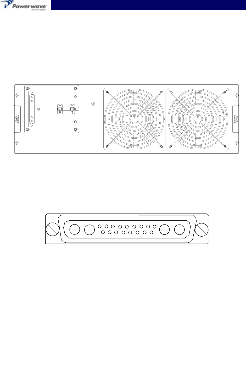
2-6 Amplifier Module Connectors
The amplifier has three connectors on the right rear of the module. The larger is a 21-pin male
D-Sub combo, which provides the status, alarm, control, and power connections. The smaller
BMA coaxial female connectors provide the RF connections. Refer to figure 2-1.
Figure 2-1 G3S-800-180-029 Amplifier, Rear View
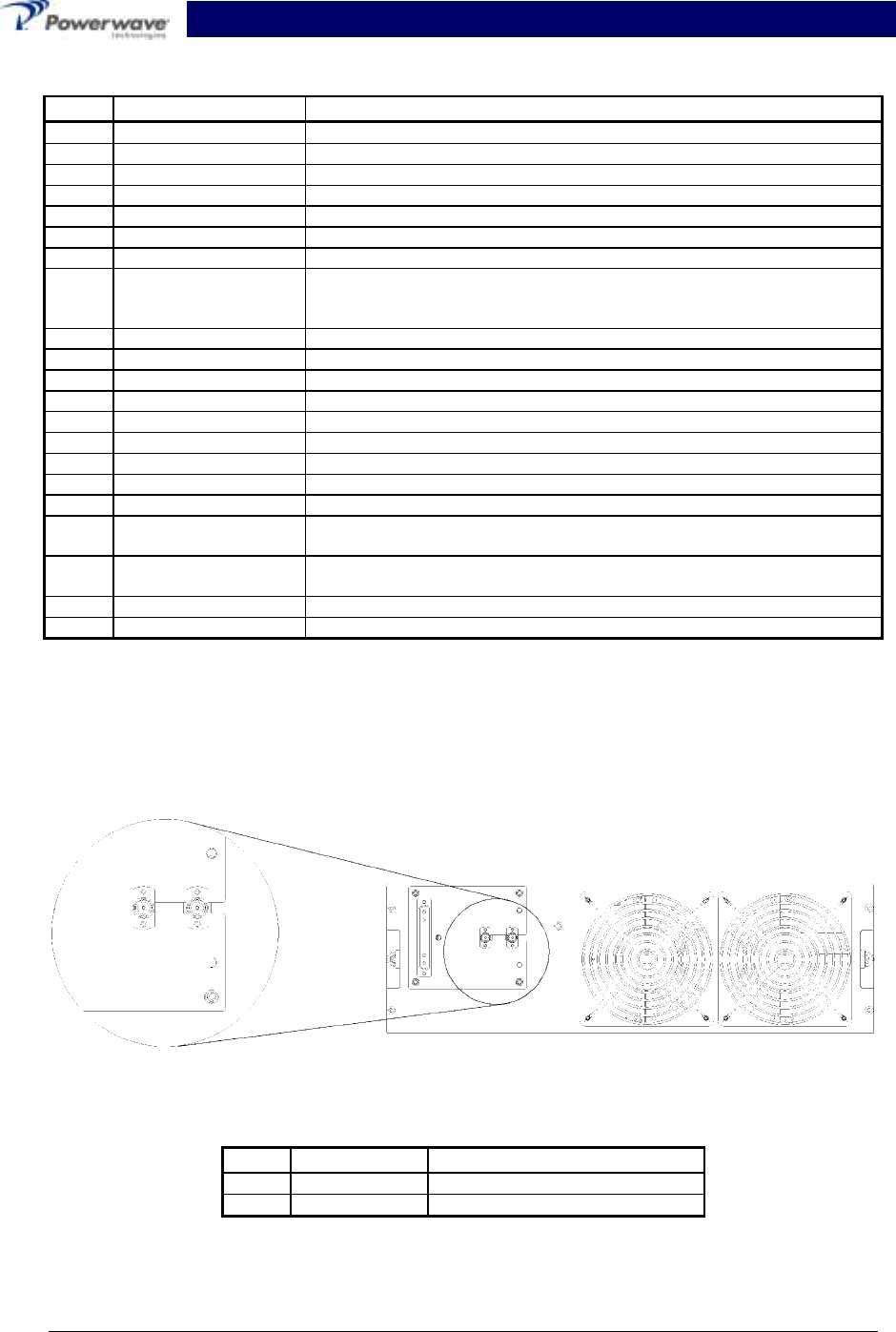
2-6.1 Amplifier Module Status, Alarm, Control, And Power Connector
The amplifier has a separate remote alarm and control connector, which may be used by the host
system to monitor and control the individual amplifier modules. The status, alarm, control, and
power connections on the amplifier connector are made through a 21-pin male D-Sub combo
connector (figure 2-2) and are listed and described in table 2-4.
A1 A2 A3 A4
1 2 3 4 5 6 7 8 9
10 11 12 13 14 15 16 17
Figure 2-2 DC and Logic Connector (on Rear of G3S-800-180-029 Amplifier Module)
G3S-800-180-029 Installation & Service Manual
Copyright Powerwave Technologies, Inc., April 2002. All rights reserved
044-05112 Rev. A 2-5 April 2002
Table 2-4 Amplifier Module DC and Logic Connector Definition
Pin Function Description
A1 Power Input +27 Vdc (Power Contact)
A2 Power Input +27 Vdc (Power Contact)
A3 Ground Ground (Power Contact)
A4 Ground Ground (Power Contact)
1 RS485 +TxD Serial Communication Data Out
2 RS485 +RxD Serial Communication Data In
3 Service Loop TTL input to Amp. Gnd. for special test mode (Note 1)
4 MCPA Disabled
(Summary Fault) TTL signal normally low indicates MCPA enabled. A high level indi-
cates that the MCPA has been disabled. Over Power, Over Voltage
takes one second to activate the signal.
5 Mod Addr 0 TTL input to Amp. Gnd. supplied by shelf to identify slot.
6 Mod Addr 1 TTL input to Amp. Gnd. supplied by shelf to identify slot.
7 TP1 TTL output. Future test point.
8 Manual Download GND to download manually
9 DC on stat TTL output. High indicates Amp is powered on.
10 RS485 –TxD Serial Communication Data Out
11 RS485 –RxD Serial Communication Data In
12 SCL7 No connection
13 SDA7 No connection
14 FP Disable Output Output, GND if the front panel switch is in the OFF position; +5 volts
indicates the front panel switch is in the ON position.
15 FP RST Output, GND if the front panel switch is in the RESET position; +5 volts
otherwise.
16 GND Ground
17 Module Detect Ground potential. Informs the subrack that an MCPA is plugged in.
Note 1: Service loop grounded allows the MCPA to be enabled or disabled by the front panel
switch when not mounted in the shelf.
2-6.2 Amplifier Module RF Connector
The amplifier has separate RF connectors, which are used for the RF signal input and output.
The RF connections on the amplifier connector are made through two BMA female coaxial con-
nectors (figure 2-3) and are listed and described in table 2-5.
Figure 2-3 Amplifier RF Connector
Table 2-5 Amplifier RF Connector Definition
Pin Function Description
A1 RF Input BMA Coaxial Female, Radiall
A2 RF Output BMA Coaxial Female, Radiall
A1 A2
G3S-800-180-029 Installation & Service Manual
Copyright Powerwave Technologies, Inc., April 2002. All rights reserved
044-05112 Rev. A 3-1 April 2002
Section 3 Operating Instructions
3-1 Introduction
This section contains operating instructions for the Multicarrier Cellular Amplifier System.
3-2 Location And Function Of Amplifier Module Controls And Indicators
Primary +27 Vdc power is applied to the amplifier via a 100-amp circuit breaker (ON-OFF) located
on the left side of the amplifier front panel.
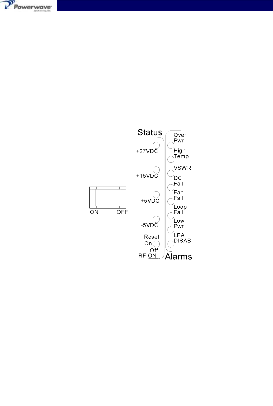
The plug-in amplifier module RF control and indicators, located in the center of the amplifier front
panel between the cooling fans, are shown in figure 3-1. The status and RF control functions and
alarms are described in detail in the subsequent paragraphs.
Figure 3-1 G3S-800-180-029 Amplifier Module RF Control and Indicators
3-2.1 Voltage Indicators And On/Off/Reset Switch
3-2.1.1 On Off Switch
This is the DC power switch for the amplifier module. The On/Off switch is a circuit breaker rated
for the inrush current and maximum current draw allowable with this amplifier module. This switch
should be in the Off position whenever the amplifier is inserted or removed from an amplifier
subrack.
3-2.1.2 RF ON Switch
Three position switch:
Off (down position) - Turns off RF section of amplifier module.
On (center position) - Normal amplifier on position.

G3S-800-180-029 Installation & Service Manual
Copyright Powerwave Technologies, Inc., April 2002. All rights reserved
044-05112 Rev. A 3-2 April 2002
Reset (up position) - When toggled to reset position, all the red LED indicators will turn on
one at a time in sequence followed by all the green indicators one at a time in sequence; this
will also reset the fault latches. If the switch is held in the reset position, a microcontroller re-
set will occur. This will be verified by the LEDs toggling state again. The switch is spring
loaded to return to the normal ON position when released. If a fault occurs and the MCPA is
disabled, the alarms can be cleared and the MCPA enabled by this reset position. The func-
tions of the switch are disabled for five seconds after a power-up condition.
3-2.1.3 +27VDC Indicator
Green LED. When lit, indicates that the +27 Vdc supply is greater than +21 Vdc and less than
+31 Vdc. If the +27 Vdc indicator goes out, the DC FAIL indicator will illuminate. This indicates
that the +27 Vdc voltage dropped below +21 Vdc.
3-2.1.4 +15VDC Indicator
Green LED. When lit, indicates that the +15 Vdc supply is greater than +12 Vdc and less than
+17 Vdc. If the +15 Vdc indicator goes out, the DC FAIL indicator will illuminate. This indicates
that the +15 Vdc voltage dropped below +12 Vdc or increased above +17 Vdc.
3-2.1.5 +5VDC Indicator
Green LED. When lit, indicates that the +5 Vdc supply is greater than +2 Vdc and less than +7
Vdc. If the +5 Vdc indicator goes out, the DC FAIL indicator will illuminate. This indicates that the
+5 Vdc voltage dropped below +2 Vdc or increased above +7 Vdc.
3-2.1.6 -5VDC Indicator
Green LED. When lit, indicates that the -5 Vdc supply is greater than -7 Vdc and less than -2 Vdc.
If the -5 Vdc indicator goes out, the DC FAIL indicator will illuminate. This indicates that the -5
Vdc voltage dropped below -7 Vdc or increased above -2 Vdc.
3-2.2 Alarm Indicators
The alarm modes described here are indicative of amplifier alarm modes made to the amplifier
subrack. The amplifier subrack interprets these alarms and may subsequently deliver a different
alarm indication to the host equipment. Refer to the amplifier subrack manual to determine host
equipment level alarms.
Refer to section 6 to interpret and correct the various alarm states.
Refer to table 3-1.
A ‘Minor Alarm’ indicates a potential fatal amplifier problem via the amplifier front panel LEDs. and
the MCPA fault will be in evaluation.
A ‘Major Alarm’ indicates a major problem but the MCPA module will not be disabled.
A ‘Critical Alarm’ is indicative of a fatal problem. The fault indicator will latch on and the MCPA
module will be disabled.
Both ‘Major Alarm’ and ‘Critical Alarm’ will be sent to the host system via the MCPA subrack.

G3S-800-180-029 Installation & Service Manual
Copyright Powerwave Technologies, Inc., April 2002. All rights reserved
044-05112 Rev. A 3-3 April 2002
Table 3-1 Amplifier Module Alarm Indicators Definition
Alarm Mode LED MCPA
Module
MCPA
Disable signal
(pin 4 inTable 2-1) Condition
Over Pwr Critical Red Disable High MCPA module output power >220
watts (Note 4)
Over Pwr Critical Red Disable High Input power >-3 dBm
High Temp Minor Red Enable Low High temperature detected
High Temp Critical Red Disable High High temperature detected for longer
than two minutes
VSWR Minor Red Enable Low 14.5 W < Reflected Power < 38W
VSWR Critical Red Disable High 60W < Reflected power detected at
output longer than approx. two min.
DC Fail Minor Red Enable Low One of the internal DC voltages
dropped below or exceeded the safe
threshold level
DC Fail Critical Red Disable High Voltage out of range for longer than
approx. two minutes (Note 2)
DC Fail
(Over
voltage) Critical Red Disable High +27 Vdc input >30 V for longer than
one sec. after initial detection of DC
input >31 V (Note 3)
Fan Fail
(one) Major Red Enable Low Any fan failure
Loop Fail Minor Red Enable Low Loop failure detected
Loop Fail Critical Red Disable High Loop failure detected longer than 2
minutes
Low Pwr Minor Red Enable Low Rack controller detected MCPA out-
put is 3 dB below that of the other
MCPA in the system.
Low Pwr Critical Red Disable High Rack controller detected low power
condition for more than approx. two
minutes
LPA
DISAB. Critical Red Disable High
Unit is manually switched off using
the front panel RF ON switch, or dis-
abled by a serial command or auto
shutdown by an alarm condition.
NOTES:
1. RS-485 serial alarm will follow LED status.
2. The appropriate status LED shall turn off indicating which voltage is out of its range.
3. When overvoltage is detected:
a) MCPA shall shut down (disable)
b) Turn on red DC Fail LED
c) Set flag for DC Fail alarm
4. When overpower is detected:
a) MCPA shall shut down (disable)
b) Turn on Over Pwr LED
c) Set flag for Over Pwr alarm
d) The MCPA module uses an RMS power detector to determine the overpower fault.

G3S-800-180-029 Installation & Service Manual
Copyright Powerwave Technologies, Inc., April 2002. All rights reserved
044-05112 Rev. A 3-4 April 2002
3-3 Initial Start-Up And Operating Procedures
The amplifier module has two operating controls, both located on the front face of the module: the
power ON - OFF switch and the RF ON - ON/OFF/RESET switch (refer to figures 1-1 and 3-1).
To perform the initial start-up, proceed as follows:
1. Verify that all input and output cables are properly connected.
CAUTION
Before applying power, make sure that the input and output of the amplifier are
properly terminated at 50 ohms. Do not operate the amplifier without a load attached.
Refer to table 1-2 for input power requirements. Excessive input power may damage
the amplifier
WARNING
Ensure the amplifier is turned off while disconnecting and reconnecting cables
between the antenna interface and power measurement equipment. Failure to do so
may cause damage to the equipment or personal injury.
NOTE
The output coaxial cable between the amplifier and the antenna must be 50 ohm coaxial
cable. Use of any other cable will distort the output.
2. Verify that the amplifier front panel switches are in the OFF position.
3. Turn on supply that provides +27 Vdc to the amplifier system. Do not apply an RF signal to
the amplifier system
4. Place the ON - OFF circuit breaker on the amplifier in the ON position. Visually check the
indicators on the amplifier module, and verify that the following indicators are on:
A. LPA DISAB. indicator (red) should be on.
B. The +27VDC, +15VDC, +5VDC and -5VDC indicators (green) on the amplifier module
should be on.
5. Set the RF ON switch to the ON (center) position. All red LEDs should turn off after six sec-
onds.
6. Follow the power setting procedure set forth in the amplifier subrack or system integration
manual. Turn on external exciter/transceiver and apply RF input signals.

G3S-800-180-029 Installation & Service Manual
Copyright Powerwave Technologies, Inc., April 2002. All rights reserved
044-05112 Rev. A 4-1 April 2002
Section 4 Principles of Operation
4-1 Introduction
This section contains a functional description of the Multicarrier Cellular Amplifier.
4-2 RF Input Signal
This amplifier may be installed in a base station system as either a stand-alone module (i.e. in a
micro-cell application), or combined with multiple amplifiers in a combining subrack product avail-
able from Powerwave. In either case, the maximum input power for all carrier frequencies should
not exceed the limits specified in table 1-2. For proper amplifier loop balance and to ensure com-
pliance with FCC rules, the out of band components of the input signals should not exceed -40
dBc. The input VSWR presented to the amplifier should be 2:1 (or better) to maximize the transfer
of input power to the amplifier; this is particularly important when the amplifier is not installed in a
Powerwave manufactured combining subrack.
4-3 RF Output Load
The load impedance should be as good as possible (1.5:1 or better) in the working band for good
power transfer to the load. If the amplifier is operated into a filter, it will maintain its distortion
characteristics outside the signal band.
4-4 G3S-800-180-029 Amplifier Module
The G3S-800-180-029 amplifier is a linear, feed-forward power amplifier that operates in the 25
MHz frequency band from 869 MHz to 894 MHz. The amplifier modules are designed for parallel
operation to achieve high peak power output, and provide system redundancy when installed in
multi-module amplifier subracks manufactured by Powerwave. The Powerwave amplifier system
is ideally suited for unmanned remote locations.
The amplifier module, figure 4-1, has an average output of 180 watts nominal power (1800 watts
peak power) with intermodulation products suppressed to better than -60 dBc below carrier levels.
The amplifier provides an amplified output signal with constant gain and phase. Constant gain and
phase is maintained by continuously comparing active paths with passive references, and cor-
recting for small variations through the RF feedback controls. All gain and phase variations, for
example those due to temperature, are reduced to the passive reference variations. Each ampli-
fier module has an alarm and display board that monitors the amplifier performance. If a failure or
fault occurs in an amplifier module, it is displayed on the individual amplifier front panel.
The amplifier module is comprised of:
Predistorter
Pre-amplifiers
Main amplifier
Error amplifier
Two feed-forward loops with phase-shift and gain controls
DC/DC power regulator
Alarm monitoring, control and display panel
The main amplifier employs class AB amplification for maximum efficiency. The error amplifier
and feed forward loops are employed to correct signal nonlinearities introduced by the class AB
main amplifier. The error amplifier operates in class AB mode. The RF input signals are ampli-
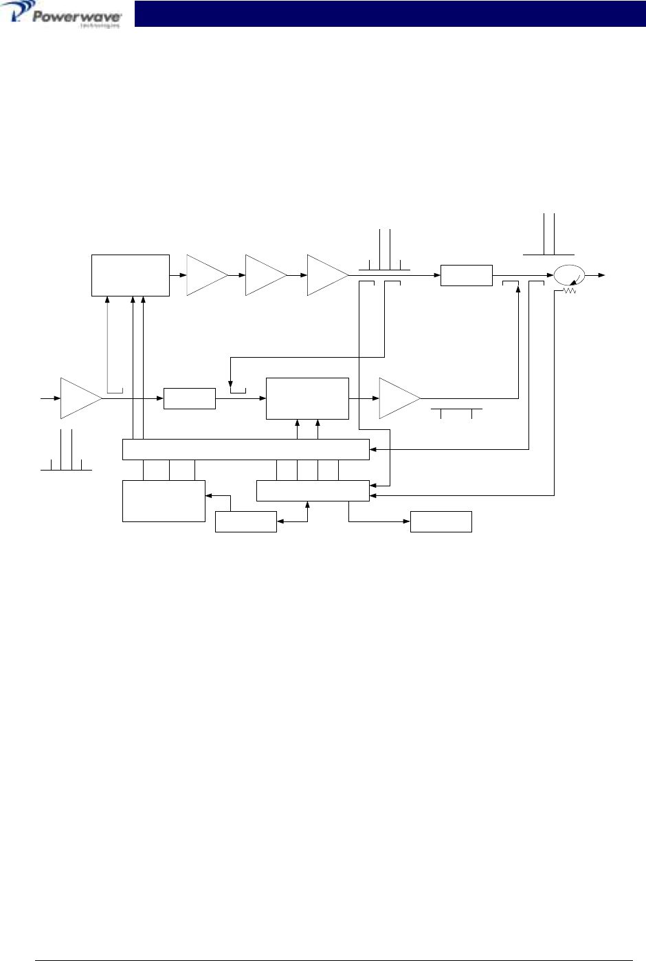
G3S-800-180-029 Installation & Service Manual
Copyright Powerwave Technologies, Inc., April 2002. All rights reserved
044-05112 Rev. A 4-2 April 2002
fied by a preamp and coupled to an attenuator and phase shifter in the first feed-forward loop.
The main signal is phase shifted by 180 degrees and amplified in the premain amplifier. The out-
put from the premain amplifier is fed to the class AB main amplifier. The output from the main
amplifier is typically 220 watts. The signal is output to several couplers and a delay structure.
The signal output from the main amplifier is sampled using a coupler, and the sample signal is
combined with the main input signal and input to the second feed-forward loop. The error signal is
attenuated, phase shifted 180 degrees, then fed to the error amplifier where it is amplified to a
level identical to the sampled output from the main amplifier. The output from the error amplifier
is then coupled back and added to the output from the main amplifier. The control loops continu-
ously make adjustments to cancel out any distortion in the final output signals.
Pre
Amp
Pre
Main Main
Amp
Error
Amp
Delay
Feed Forward Loop control
2nd Loop
Phase & Gain
1st Loop
Phase & Gain Delay
Alarms & Display
+15 +5 -5
Power Supply
-30dB -10dB
RF Out
RFL
PWR
FWD
PWR
Front Panel
Smart Rack
+27VDC
Pre
Dist
Figure 4-1 G3S-800-180-029 Power Amplifier Module Functional Block Diagram
4-4.1 Main Amplifier
The input and output of the amplifier employ two-stage, class AB amplifiers which provide ap-
proximately 32 dB of gain in the 25 MHz frequency band from 869 to 894 MHz. The amplifier op-
erates on +27 Vdc, and a bias voltage of +5 Vdc, and is mounted directly on a heat sink that is
temperature monitored by a thermostat. If the heat sink temperature exceeds 90° C, a high tem-
perature fault occurs. The alarm logic controls the +5 Vdc bias voltage that shuts down the ampli-
fier.
4-4.2 Error Amplifier
The main function of the error amplifier is to amplify the distortion signal generated by the 1st
Loop, to a level that cancels out the distortion and IMD when the error signal is coupled onto the
main signal at the amplifier output. The error amplifier is a balanced multistage, class AB ampli-
fier.
4-4.3 Amplifier Monitoring
In the main and error amplifier modules, all normal variations are automatically compensated for
by the feedforward loop control. However, when large variations occur beyond the adjustment
range of the loop control, a loop fault will occur. The alarms are displayed on the front panel indi-
cators and output via a 21-pin connector on the rear of the module to the subrack summary board

G3S-800-180-029 Installation & Service Manual
Copyright Powerwave Technologies, Inc., April 2002. All rights reserved
044-05112 Rev. A 4-3 April 2002
for subsequent remote monitoring via the ALARMS connector. Refer to paragraph 2-6 as well as
figure 2-2 and table 2-3 for a description of the ALARMS connector.
4-4.4 Amplifier Module Cooling
Although each amplifier module contains its own heat sink, it is cooled with forced air. Four fans
are used for forced air-cooling and redundancy. The fans, located on the front and rear of the
amplifier module, draw air in through the front of the amplifier and exhaust hot air out the back of
the module. The fans are field replaceable.
4-5 Power Distribution
Primary DC power for the system is provided by the host system to the MCR30829-1-3 Series or
compatible subrack. The subrack supplies each amplifier module with +27 Vdc directly and via
the RF power splitter/combiner. The amplifier module has a DC/DC converter that converts the
+27 Vdc to +15 Vdc, +5 Vdc and -5 Vdc.
4-6 Intermodulation
The G3S-800-180-029 amplifier is designed to deliver a 180-watt nominal composite average
power (210 W max.), multi-carrier signal, occupying a bandwidth less than or equal to 25 MHz, in
the band from 869 to 894 MHz. The maximum average power for linear operation, and thus the
amplifier efficiency, will depend on the type of signal amplified.
Three or more CW tones of equal input power will lower individual intermodulation products. If the
frequencies are not equally spaced, the level of intermodulation products gets very low. When the
frequencies are equally spaced, those products fall on top of each other on the same frequency
grid. The average power of all intermodulation beats falling on the same frequency is called the
composite intermodulation; it is -60 dBc or better.
4-7 Alarms
The presence of several plug-in amplifier alarms can be detected at the DC and logic connector
on the amplifier rear panel. Refer to table 2-3 and figure 2-2 for a description of the connector.

G3S-800-180-029 Installation & Service Manual
Copyright Powerwave Technologies, Inc., April 2002. All rights reserved
044-05112 Rev. A 5-1 April 2002
Section 5 Maintenance
5-1 Introduction
This section contains periodic maintenance and performance test procedures for the Multicarrier
Cellular Amplifier. It also contains a list of test equipment required to perform the identified tasks.
NOTE
Check your sales order and equipment warranty before attempting to service or repair
the unit. Do not break the seals on equipment under warranty or the warranty will be
null and void. Do not return equipment for warranty or repair service until proper
shipping instructions are received from the factory.
5-2 Periodic Maintenance
Periodic maintenance requirements are listed in table 5-1. Table 5-1 also lists the intervals at
which the tasks should be performed.
WARNING
Wear proper eye protection to avoid eye injury when using compressed air.
Table 5-1 Periodic Maintenance
Task Interval Action
Cleaning
Air Vents 30 Days Inspect and clean per paragraph 5-4
Inspection
Cables and Connec-
tors 12 Months Inspect signal and power cables for
frayed insulation. Check RF connectors
to be sure that they are tight.
Performance Tests 12 Months Perform annual test per paragraph 5-5.
5-3 Test Equipment Required For Test
Test equipment required to test the amplifier system is listed in table 5-2. Equivalent test equip-
ment may be substituted for any item, keeping in mind that a thermistor type power meter is re-
quired.
NOTE
All RF test equipment must be calibrated to 0.05 dB resolution. Any deviation from the
nominal attenuation must be accounted for and factored into all output readings.

G3S-800-180-029 Installation & Service Manual
Copyright Powerwave Technologies, Inc., April 2002. All rights reserved
044-05112 Rev. A 5-2 April 2002
Table 5-2 Test Equipment Required
Nomenclature Manufacturer Model
Signal Generator RDL IMD-801D-03A
30 dB Attenuator, 500 Watt Weinschel Corp. 53-30-34
20 dB Attenuator, 20 Watt
(2 each) Tenuline
Spectrum Analyzer H.P. 8560E
Coax Directional Coupler H.P. 778D
Power Meter/Sensor H.P. 437B/8481A
Network Analyzer H.P. 8753C
Current Probe
5-4 Cleaning Air Inlets/Outlets
The air inlets and outlets should be cleaned every 30 days. If the equipment is operated in a se-
vere dust environment, they should be cleaned more often as necessary. Turn off DC power
source before removing fans. If dust and dirt are allowed to accumulate, the cooling efficiency
may be diminished. Using either compressed air or a brush with soft bristles, loosen and remove
accumulated dust and dirt from the air inlet panels.
5-5 Performance Test
Performance testing should be conducted every 12 months to ensure that the amplifier system
meets the operational specifications listed in table 5-3. Also verify system performance after any
amplifier module is replaced in the field. The test equipment required to perform the testing is
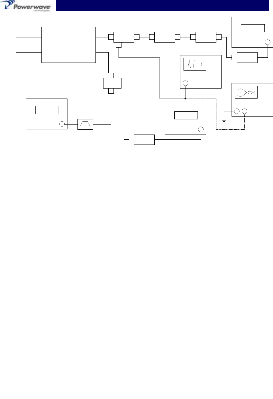
listed in table 5-2, and the test setup is shown in figure 5-1.
NOTE
The frequencies used in this test are typical for an amplifier with a 25 MHz band from
869 MHz to 894 MHz. Select evenly spaced F1, F2, F3, and F4 frequencies that cover the
instantaneous bandwidth of your system.
5-5.1 Amplifier System Performance Test
This test is applicable to the G3S-800-180-029 amplifier modules. To perform the test, proceed as
follows:
1. Connect test equipment to the amplifier as shown in figure 5-1.
NOTE
Do not apply any RF signals at this time.
Turn on signal generator and set frequency F1 to 880 MHz, F2 to 883 MHz, F3 to 886 MHz,
and F4 to 889 MHz. Adjust each signal generator output so that the sum power output from
all four signal generators equals -6 dBm at the input.
G3S-800-180-029 Installation & Service Manual
Copyright Powerwave Technologies, Inc., April 2002. All rights reserved
044-05112 Rev. A 5-3 April 2002
Unit Under Test
G3S-800-180
Plug-in
Amplifier
Module
+27 Vdc
Gnd RF In
RF
Out
20 dB
Directional Coupler 30 dB
Attenuator
500 W
20 dB
Attenuator
20 W Power Meter
Sensor Head
8482A
1:2
Splitter
Power Meter
Sensor Head
8482A
Network Analyzer
8753C
Signal
Generator
Filter /
Isolator
Spectrum Analyzer
8651E
Figure 5-1 Amplifier System Test Setup Diagram
5-5.1.1 Amplifier IMD Test And Current Test
2. Adjust attenuator for an input signal at -10 dBm. Turn on the amplifier by setting RF ON
switch of amplifier. Adjust variable attenuator to set amplifier power output on power meter to
180 watts. Measure IMD on spectrum analyzer. IMD should be -60 dBc max. Record test
data in table 5-3. Set RF ON switch to OFF.
3. With the amplifier module set at 180 watts power output, use the current probe (magnetic
field type) and measure the dc current flow from the +27 Vdc power source. Current should
be 70 amps maximum. Record test data in table 5-3.
5-5.1.2 Gain Test
4. Disconnect spectrum analyzer from test setup, and connect the network analyzer.
5. Set network analyzer as follows:
Ø Power output to -10 dBm.
Ø Frequency start to 869 MHz.
Ø Frequency stop to 894 MHz.
Ø Normalize the network analyzer for gain and return loss.
6. Check the gain across the band from 869 MHz to 894 MHz. Gain should be between 58 dB.
Record test data in table 5-3.
5-5.1.3 Harmonics Test
7. With the power set at 180 watts power output, use the spectrum analyzer and check the fre-
quency band from 869 MHz to 894 MHz for harmonics. Harmonics should be 5 dBm maxi-
mum. Record test data in table 5-3.
G3S-800-180-029 Installation & Service Manual
Copyright Powerwave Technologies, Inc., April 2002. All rights reserved
044-05112 Rev. A 5-4 April 2002
5-5.1.4 Spurious Test
8. With the power amplifier set at 180 watts power output, use the spectrum analyzer and check
the frequency band from 869 MHz to 894 MHz for spurious signals. Spurious signals should
be -60 dBc maximum. Record test data in table 5-3.
5-5.1.5 Input Return Loss Test
9. Reset and turn on amplifier module. Read and record the S11 return loss measurement on
network analyzer. Input return loss should be –16 dB maximum. Record test data in table
5-3.
Table 5-3 Multicarrier Cellular Amplifier Test Data Sheet
DATE _________________________________
AMPLIFIER S/N _________________________
TEST CONDITIONS:
Load and Source Impedance: 50 Ohms
VSWR: < 1.2:1
Supply Voltage: +27 Vdc ±1.0 Vdc
TEST SPECIFICATION MIN MAX DATA
4-TONE IMD Vcc = 27 Vdc
PO = 180 W
Freq.: 880, 883, 886, and 889
MHz
-60 dBc
RF Gain Vcc = 27 Vdc
PO = 180 W
Freq. = 880 MHz 57.5 dB 58.5 dB
Gain Flatness Vcc = 27 Vdc ±1 Vdc
PO =180 W
869-894 MHz Band -0.5 dB +0.5 dB
Harmonics Vcc = 27 Vdc
PO = 180 W
869-894 MHz Band 5 dBm
Spurious Vcc = 27 Vdc
PO =180 W
869-894 MHz Band -60 dBc
Input Return
Loss
Vcc = 27 Vdc
PO = 180 W
869-894 MHz Band -16 dB
DC Power Vcc = 27 Vdc
PO = 180 W
4 Tones 70 Amps
PASS _________________________________ FAIL _______________________________
Tested by ______________________________
G3S-800-180-029 Installation & Service Manual
Copyright Powerwave Technologies, Inc., April 2002. All rights reserved
044-05112 Rev. A 5-5 April 2002
5-6 Field Replaceable Parts And Modules
The following parts and modules can be replaced in the field on site by a qualified technician with
experience maintaining RF power amplifiers and similar equipment:
1. G3S-800-180-029 power amplifier modules
2. Cooling fans
5-6.1 G3S-800-180-029 Power Amplifier Module
To replace a power amplifier module, proceed as follows:
1. Set both the RF ON On/Off/Reset switch and the power ON/OFF switch on the front panel of
the amplifier module to OFF.
2. Loosen two screws that secure amplifier module to subrack.
CAUTION
The amplifier is equipped with a spring clip on each side panel to prevent the amplifier
from being fully removed from the subrack via the front panel handles. When removing
the amplifier from the subrack, it is very important to support the amplifier such that the
rear of the module does not suddenly drop when it disengages from the track. A drop
such as this could damage the module or cause personal injury.
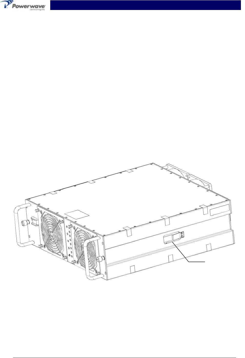
Figure 5-2 Amplifier Spring Clip Location
3. Use the handle on the front of the module, and with a steady even pressure, gently pull the
module about half way out of subrack until the spring-clips prevent the amplifier from being
removed (refer to figure 5-2).
4. Simultaneously press the front half of each spring clip towards the center of the amplifier and
resume removal of the amplifier.
Spring Clip

G3S-800-180-029 Installation & Service Manual
Copyright Powerwave Technologies, Inc., April 2002. All rights reserved
044-05112 Rev. A 5-6 April 2002
5-6.2 Cooling Fans
To replace a front cooling fan, proceed as follows:
1. Loosen four snap fasteners that secure fan to amplifier module. Disconnect fan power con-
nector from amplifier module.
To replace a rear cooling fan, proceed as follows:
1. Remove amplifier module from subrack; see paragraph 5-6.1 preceding.
1. Loosen the four Phillips head screws that secure the fan to the amplifier module. Disconnect
the fan power connector from the amplifier module.

G3S-800-180-029 Installation & Service Manual
Copyright Powerwave Technologies, Inc., April 2002. All rights reserved
044-05112 Rev. A 6-1 April 2002
Section 6 Troubleshooting
6-1 Introduction
This section contains a list of problems and a few suggested actions that may correct the prob-
lem. If the suggested corrective action does not eliminate the problem, please contact your Pow-
erwave field representative or the factory for further instructions.
NOTE
Check your sales order and equipment warranty before attempting to service or repair
the unit. Do not break the seals on equipment under warranty or the warranty will be
null and void. Do not return equipment for warranty or repair service until proper
shipping instructions are received from the factory.
6-2 Troubleshooting
The following are general guidelines established to aid Field Engineers or Cell Site Technicians in
the proper method of Powerwave equipment fault resolution by fault mode.
6-2.1 DC Voltage Indicators Not Illuminated
1. Check the front panel ON/OFF switch.
2. Check the power plant circuit breaker.
3. Check for +27 + 1.0 VDC at the amplifier subrack input.
A. If the voltage is low, verify that all DC connections between the power plant and the am-
plifier subrack are tight.
B. If the voltage is correct,
1. Remove the amplifier from the subrack slot and move the amplifier to another am-
plifier subrack slot.
2. Check the voltage on the power pins of the mating amplifier and amplifier subrack
connector.
3. Verify that the amplifier DC connections are not damaged.
4. Return the amplifier to the factory for repair.
6-2.2 OVER PWR Illuminated or Blinking
1. If all the amplifiers in a given amplifier subrack are in Over Pwr and the LPA Disable LED is
illuminate, then the input RF power level is too high and the amplifiers have been turned off.
RF power may be incorrectly set during equipment commissioning. This may be due to a
faulty jumper cable. Verify the amplifier subrack output cables, transmit filter, and directional
coupler are in proper working order. The loss between the amplifier subrack and the hatch
plate is typically less than 2.0 dB.
2. If all the amplifiers in a given amplifier subrack are in Over Pwr and the LPA Disable LED is
not illuminated, then the input RF power level is too high. The amplifier subrack is attempting
to maintain a safe power output level (smart subracks with True RMS power detectors and
voltage variable attenuators only). RF power may be incorrectly set during equipment com-
missioning. This may be due to a faulty jumper cable. Verify the amplifier subrack output ca-

G3S-800-180-029 Installation & Service Manual
Copyright Powerwave Technologies, Inc., April 2002. All rights reserved
044-05112 Rev. A 6-2 April 2002
bles, transmit filter, and directional coupler are in proper working order. The loss between the
amplifier subrack and the hatch plate is typically less than 2.0 dB.
3. If only one or two amplifiers in a given amplifier subrack are in Over Pwr and the LPA Disable
LED is blinking, then the amplifier subrack is probably in Sleep Mode (smart subracks with
True RMS power detectors and voltage variable attenuators only).
A. Pressing the On/Off/Reset switch momentarily in the Up position or cycling DC power on
the amplifier should bring the amplifier back on-line.
B. Sleep Mode firmware may be disabled in the field with a PC interface and software
available from Powerwave.
4. Move the amplifier to another slot in a different subrack, if available. Mark the amplifier with a
sticker or place a tie wrap on the handle to identify the amplifier. Monitor for future failure.
A. If the same amplifier fails again, return the amplifier to the factory for repair.
B. If the replacement amplifier in the original subrack fails, replace the amplifier subrack.
6-2.3 HIGH TEMP Illuminated
5. If an amplifier is in HIGH TEMP and the LPA Disable LED is illuminate, then the amplifier
heat sink temperature is too high. This may be due to:
A. High ambient temperature.
B. Fan failure.
C. Insufficient air-volume capacity. Most of Powerwave’s amplifiers require a certain
amount of free-space to allow proper airflow.
6. Correct the heat problem, then reset the amplifier by momentarily pressing the Reset button
on the amplifier front panel up.
6-2.4 VSWR Illuminated
7. If all the amplifiers in a given amplifier subrack are in VSWR and the LPA Disable LED is il-
luminate, then the output RF reflected power level is too high and the amplifiers have been
turned off. This may be due to a faulty jumper cable or transmit filter. Verify the amplifier
subrack output cables, transmit filter, and directional coupler are in proper working order. The
loss between the amplifier subrack and the hatch plate is typically less than 2.0 dB. This fault
normally occurs during site or just following site power setting and normally takes about 10 to
15 minutes to reveal itself. This fault may not occur at low power levels (i.e. when just one or
two channels are up).
8. If one amplifier in an amplifier subrack is in VSWR and the LPA Disable LED is illuminated,
then the output RF reflected power level is too high for that amplifier. This may be due to
A. A damaged or recessed amplifier RF output connector. Return the amplifier to the fac-
tory for repair.
Mishandling of the amplifier normally causes recessed pins. Before installing an ampli-
fier, look at the D-sub connector to ensure none of the pins are recessed, bent or that
the outer connector shield is not damaged. When installing the amplifier, do not force
the amplifier into the slot. Gentle even pressure is all that is needed to properly seat the
amplifier.
B. Improper seating of the amplifier.
1. Ensure the amplifier thumbscrews are properly tightened.
2. Try seating the amplifier in another subrack slot.
3. Try seating the amplifier in a subrack in another sector.

G3S-800-180-029 Installation & Service Manual
Copyright Powerwave Technologies, Inc., April 2002. All rights reserved
044-05112 Rev. A 6-3 April 2002
6-2.5 DC FAIL Illuminated
If an amplifier is in DC FAIL and the LPA Disable LED is illuminate, then one of the four amplifier
DC voltages is either out of tolerance or not present. Return the amplifier to the factory for repair.
6-2.6 FAN FAIL Illuminated
If an amplifier is in FAN FAIL, then the one of the amplifier’s cooling fans has failed. Replace the
fan.
Fan failure does not cause the amplifier to shut down; amplifier shut down is determined by heat
sink temperature.
6-2.7 LOOP FAIL Illuminated
9. Loop Fail is always accompanied by LPA Disable LED illuminated. This may be due to
A. Inability of the amplifier to maintain a 180° phase shift between the first and second
loops.
B. A damaged error amplifier. This can be caused by
1. Out of band spurious or intermods being applied at too high of a level at the ampli-
fier input port. An input band-pass filter may be necessary to correct this problem.
2. Disconnecting amplifier RF output cables while the amplifier is still turned on. Al-
ways turn the amplifier off when moving output RF cables from the hatch plate to
test equipment and back again.
C. Improper power balance between amplifiers in a given subrack.
1. Ensure the amplifier thumbscrews are properly tightened. Reset the amplifier by
momentarily pressing the Reset button on the amplifier front panel up.
2. Try seating the amplifier in another subrack slot.
3. Try seating the amplifier in a subrack in another sector.
6-2.8 LOW PWR Illuminated
Low Power is always accompanied by the LPA Disable LED illuminated. This is due to the gain of
either the internal preamplifier or main amplifier being 0.5 dB (typically) or more below the ampli-
fier specification. The amplifier should be returned to the factory.
6-2.9 LPA DISABLE Illuminated
10. LPA Disable LED illuminated indicates that the amplifier RF section is turned off. This may
be due to
A. An accompanied alarm indicating a critical amplifier fault (i.e. Loop Fail fault).
B. A response to a subrack command, purposely inhibiting the amplifier (i.e. Sleep Mode
activation)
C. Improper seating of the amplifier in the subrack.
11. Ensure the amplifier thumbscrews are properly tightened. Reset the amplifier by momentarily
pressing the Reset button on the amplifier front panel up.
12. Try seating the amplifier in another subrack slot.
13. Try seating the amplifier in a subrack in another sector.

G3S-800-180-029 Installation & Service Manual
Copyright Powerwave Technologies, Inc., April 2002. All rights reserved
044-05112 Rev. A 6-4 April 2002
6-3 Return For Service Procedures
When returning products to Powerwave, the following procedures will ensure optimum response.
6-3.1 Obtaining An RMA
A Return Material Authorization (RMA) number must be obtained prior to returning equipment to
the factory for service. Please contact our Repair Department at (888) 797-9283 or (714) 466-
1000 to obtain this number, or FAX your request to (714) 466-5816. Failure to obtain this RMA
number may result in delays in receiving repair service.
6-3.2 Repackaging For Shipment
To ensure safe shipment of the amplifier, it is recommended that the package designed for the
amplifier be used. The original packaging material is reusable. If it is not available, contact
Powerwave’s Customer Service Department for packing materials and information.