Powerwave Technologies 5JS0062 GSM/EDGE Booster Amplifier, SPA9329-35 User Manual PAF 0850 001
Powerwave Technologies Inc GSM/EDGE Booster Amplifier, SPA9329-35 PAF 0850 001
Contents
- 1. Manual
- 2. User Manual
Manual

1930-1990 MHz
Installation and Service
Manual
Model SPA9329-35
Booster Power Amplifier
Copyright Powerwave Technologies, Inc., October 2002. All rights reserved
October 2002

SPA9329-35 Installation & Service Manual
October 2002
© 2002 Powerwave Technologies Incorporated. All rights reserved.
Powerwave Technologies, and the Powerwave logo are registered trademarks
Powerwave Technologies, Inc. reserves the right to make changes to the documentation and
equipment, including but not limited to component substitution and circuitry changes. Changes that
impact this manual may subsequently be incorporated in a later revision of this manual.
Powerwave Technologies, Inc. Tel: (714) 466-1000
1801 East St. Andrew Place (888) 797-9283
Santa Ana, CA 92705 Fax: (714) 466-5800
Web Site: www.powerwave.com
Copyright Powerwave Technologies, Inc., October 2002. All rights reserved
ii October 2002

SPA9329-35 Installation & Service Manual
Table Of Contents
Par. Section 1 Page
No. General Description No.
1-1 Introduction ..................................................................................................................................................... 1-1
1-2 General Description....................................................................................................................................... 1-1
1-3 Functional and Physical Specifications.................................................................................................... 1-1
1-4 Ordering Information ..................................................................................................................................... 1-1
Section 2
Installation
2-1 Introduction ..................................................................................................................................................... 2-1
2-2 Electrical Service Recommendations........................................................................................................ 2-1
2-3 Unpacking and Inspection............................................................................................................................ 2-1
2-4 Installation Instructions................................................................................................................................ 2-2
2-5 +27 VDC Power & Ground Connector ......................................................................................................... 2-2
Section 3
Operating Instructions
3-1 Introduction ..................................................................................................................................................... 3-1
3-2 Initial Start-Up and Operating Procedures ............................................................................................... 3-1
Section 4
Principles of Operation
4-1 Introduction ..................................................................................................................................................... 4-1
4-2 RF Input Signal................................................................................................................................................ 4-1
4-3 RF Output Load ................................................................................................................................................ 4-1
4-4 Amplifier Functional Description................................................................................................................ 4-1
4-5 Amplifier Module Cooling ............................................................................................................................ 4-1
4-6 Power Distribution......................................................................................................................................... 4-2
Section 5
Maintenance
5-1 Introduction ..................................................................................................................................................... 5-1
5-2 Periodic Maintenance................................................................................................................................... 5-1
5-3 Module Field Replacement .......................................................................................................................... 5-1
Section 6
Troubleshooting
6-1 Introduction ..................................................................................................................................................... 6-1
6-2 Trouble shooting............................................................................................................................................. 6-1
6-3 Return for Service Procedures .................................................................................................................... 6-1
6-3.1 Obtaining an RMA .......................................................................................................................................... 6-1
6-3.2 Repackaging for Shipment ........................................................................................................................... 6-1
Copyright Powerwave Technologies, Inc., October 2002. All rights reserved
October 2002
iii

SPA9329-35 Installation & Service Manual
List Of Illustrations
Figure Page
No. No.
1-1 SPA9329-35 Front Isometric View ......................................................................................................... 1-3
1-2 SPA9329-35 Rear Isometric View .......................................................................................................... 1-3
1-3 SPA9329-35 Front View............................................................................................................................ 1-4
1-4 SPA9329-35 Rear View ............................................................................................................................ 1-4
1-5 SPA9329-35 Side View............................................................................................................................. 1-5
2-1 +27Vdc Power & Ground Connector........................................................................................................... 2-2
3-1 SPA9329-35 Front Panel Indicators ....................................................................................................... 3-2
4-1 SPA9329-35 Booster Amplifier Block Diagram................................................................................... 4-1
List Of Tables
Table Page
No. No.
1-1 Major System Components........................................................................................................................... 1-1
1-2 SPA9329-35 Power Amplifier Functional Specifications ................................................................. 1-2
2-1 +27Vdc Power & Ground Connector Descriptions................................................................................... 2-2
3-1 SPA9329-35 Controls, Indicators, and Connectors............................................................................. 3-1
5-1 Periodic Maintenance................................................................................................................................... 5-1
6-1 Troubleshooting.............................................................................................................................................. 6-1
Copyright Powerwave Technologies, Inc., October 2002. All rights reserved
October 2002
iv

SPA9329-35 Installation & Service Manual
Section 1 General Description
1-1 Introduction
This manual contains information and procedures for installation, operation, and maintenance of
Powerwave’s model SPA9329-35 channel booster power amplifier. The manual is organized
into six sections as follows:
Section 1. General Description
Section 2. Installation
Section 3. Operating Instructions
Section 4. Principles of Operation
Section 5. Maintenance
Section 6. Troubleshooting
1-2 General Description
The SPA9329-35 is a linear booster amplifier that operates in a frequency range from 1930
MHz to 1990 MHz and provides 100 watts (50 dBm) of output power with a maximum gain of 23
dB. The amplifier is modular in design, and is ideally suited for use in GSM and EDGE base sta-
tions.
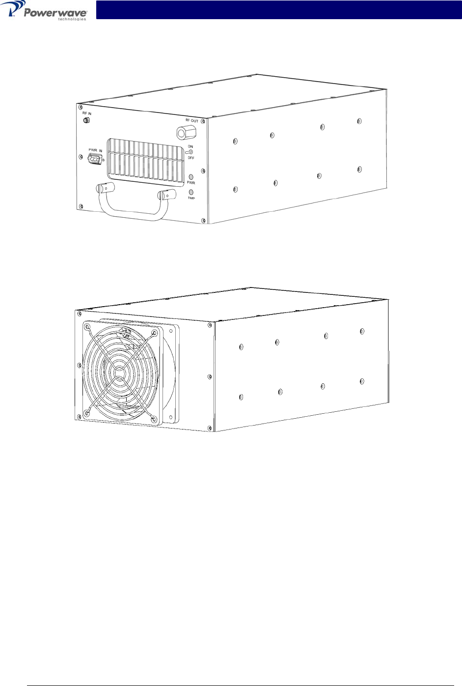
The amplifier is shown in figures 1-1 through 1-5. Each amplifier module has a power input, one
RF input, and an RF output. Controls and indicators consist of a DC power switch with corre-
sponding LED power indicator and an amplifier over-temperature LED indicator (see section 3).
Primary power input for the amplifier is +27 VDC. Cooling for the amplifier module is provided by
one fan mounted on the rear of the amplifier module, shown in figure 1-1, which provides airflow
over the two internal heat sinks.
1-3 Functional & Physical Specifications
Functional and physical specifications for the amplifier are listed in table 1-2.
1-4 Ordering Information
Table 1-1 lists the component numbers and descriptions to be used when ordering booster ampli-
fiers or components.
Table 1-1 Major System Components
Component
Number Description
SPA9329-35 100-Watt Amplifier, +27 VDC
Copyright Powerwave Technologies, Inc., October 2002. All rights reserved
1-1 October 2002

SPA9329-35 Installation & Service Manual
Table 1-2 SPA9329-35 Booster Power Amplifier Functional Specifications
Parameters +27 VDC Power Model
Frequency Range 1930-1990 MHz
Carrier Spacing (center
to center)
200 kHz nominal
Occupied Bandwidth < 200 kHz/carrier
Max Power Output per
Carrier
100 Watts (50 dBm)
Maximum Module Gain 23 dB ± 1 dB
Max Tx Input Level for
100 Watts
0.5 Watts (27 dBm)
Spurious Emissions -65 dBc
Gain Flatness Across
20 MHz Band
±0.5 dBm Maximum
Operating Voltage +27 VDC
Operating Current (per
Input Connector X2)
24 Amps @ +27 VDC
Operating Temperature: -0 ºC to +50 ºC
Tx Input Connector SMA-F
Tx Output Connector Type ‘N’ Female
Dimensions (+27 VDC
Model)
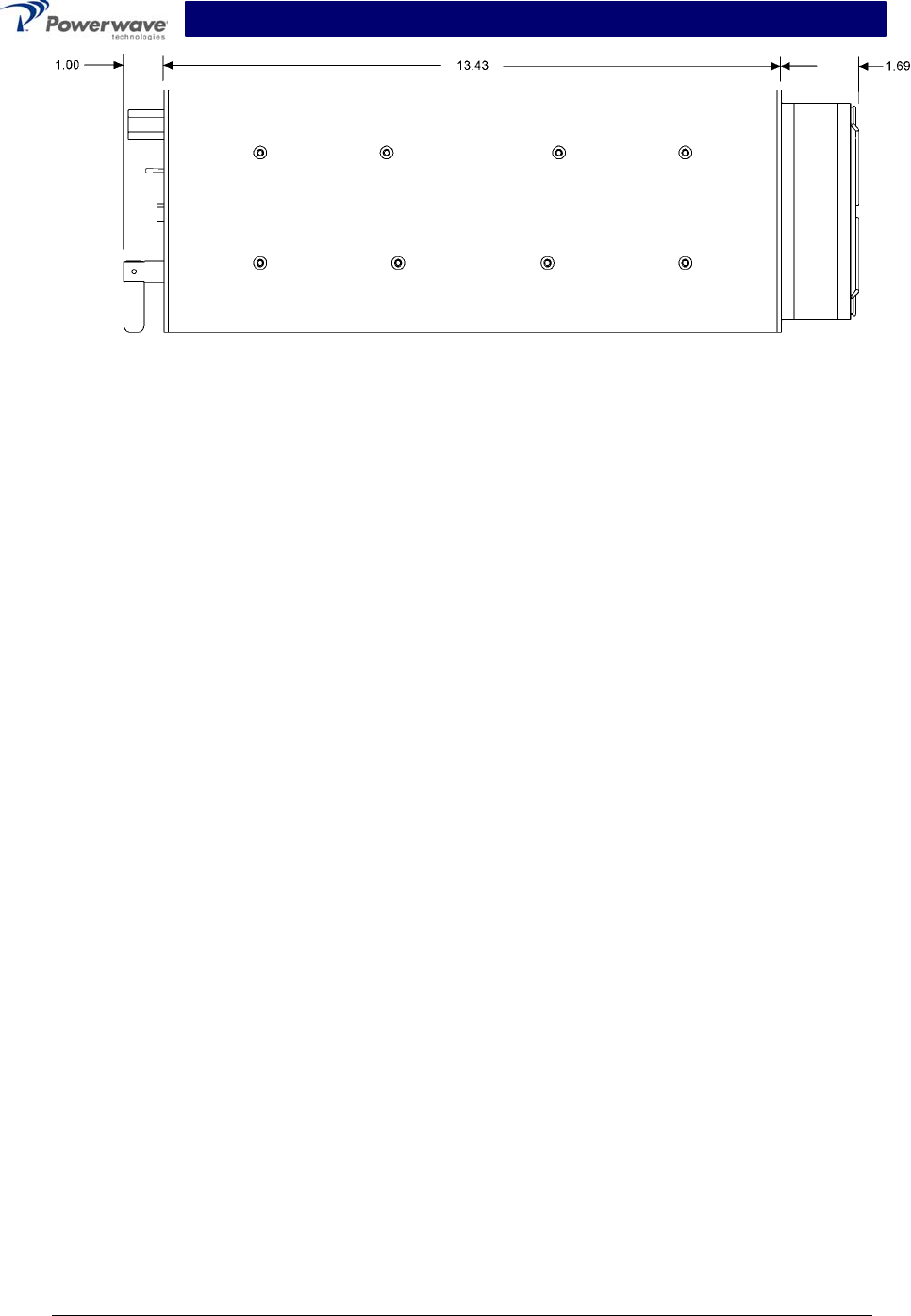
5.25”H x 8.5”W x 16.1”D
Mounting Options 19”, 23”, or 24” relay rack mounted or outdoor
enclosure mounted
Weight 12 lbs maximum
Copyright Powerwave Technologies, Inc., October 2002. All rights reserved
1-2 October 2002
SPA9329-35 Installation & Service Manual
Figure 1-1. SPA9329-35 Front Isometric View
Figure 1-2. SPA9329-35 Rear Isometric View
Copyright Powerwave Technologies, Inc., October 2002. All rights reserved
1-3 October 2002
SPA9329-35 Installation & Service Manual
Figure 1-3. SPA9329-35 Front View
Figure 1-4. SPA9329-35 Rear View
Copyright Powerwave Technologies, Inc., October 2002. All rights reserved
1-4 October 2002
SPA9329-35 Installation & Service Manual
Figure 1-5. SPA9329-35 Side View
Copyright Powerwave Technologies, Inc., October 2002. All rights reserved
1-5 October 2002

SPA9329-35 Installation & Service Manual
Section 2 Installation
2-1 Introduction
This section contains unpacking, inspection, and installation instructions and recommendations
for the Powerwave model SPA9329-35 booster power amplifier. Carefully read all material in
this section prior to equipment unpacking or installation. Also read and review the operating pro-
cedures in section 3 prior to installing the equipment. It is important that the licensee perform
these tasks correctly and in good faith. If applicable, carefully read the appropriate parts of the
Federal Communications Commission (FCC) rules to determine how they apply to your installa-
tion. DON'T TAKE CHANCES WITH YOUR LICENSE.
2-2 Electrical Service Recommendations
Powerwave Technologies recommends that proper AC line conditioning and surge suppression
be provided on the primary AC input to the +27 Vdc power source. All electrical service should be
installed in accordance with the National Electrical Code, any applicable state or local codes, and
good engineering practice. Special consideration should be given to lightning protection of all
systems in view of the vulnerability of most transmitter sites to lightning. Lightning arrestors are
recommended in the service entrance. Straight, short ground runs are recommended. The elec-
trical service must be well grounded.
Each amplifier system should have its own circuit breaker, so a failure in one does not shut off
the whole installation. Circuit breakers should be thermal type, capable of handling the maximum
anticipated inrush current, in a load center with a master switch.
2-3 Unpacking & Inspection
This equipment has been operated, tested and calibrated at the factory. Carefully open the con-
tainer(s) and remove the amplifier module(s). Retain all packing material that can be reassem-
bled in the event that the unit must be returned to the factory.
CAUTION
Exercise care in handling equipment during inspection to prevent damage caused by
rough or careless handling.
Visually inspect the amplifier module for damage that may have occurred during shipment. Check
for evidence of water damage, bent or warped chassis, loose screws or nuts, or extraneous pack-
ing material in the connector. If the equipment is damaged, a claim should be filed with the carrier
once the extent of any damage is assessed. We cannot stress too strongly the importance of
IMMEDIATE careful inspection of the equipment and the subsequent IMMEDIATE filing of the
necessary claims against the carrier if necessary. If possible, inspect the equipment in the pres-
ence of the delivery person. If the equipment is damaged, the carrier is your first area of re-
course. If the equipment is damaged and must be returned to the factory, write or phone for a re-
turn authorization. Powerwave may not accept returns without a return authorization. Claims for
loss or damage may not be withheld from any payment to Powerwave, nor may any payment due
be withheld pending the outcome thereof. WE CANNOT GUARANTEE THE FREIGHT CAR-
RIER'S PERFORMANCE
Copyright Powerwave Technologies, Inc., October 2002. All rights reserved
2-1 October 2002
SPA9329-35 Installation & Service Manual
2-4 Installation Instructions
The SPA9329-35 booster amplifier module is designed for installation in an enclosure that
permits access to the front of the module for connection of the RF cables and the power connec-
tors.
WARNING
Turn external primary DC power off before connecting any cables.
1. Connect the +27 VDC power source to the booster power input connector (see figures 2-1,
3-1, and table 2-1). Do not apply power at this time.
2. Connect the RF input cable to the RF IN connector.
3. Connect the RF output cable to the RF OUT connector.
4. Refer to section 3 for initial turn-on and checkout procedures.
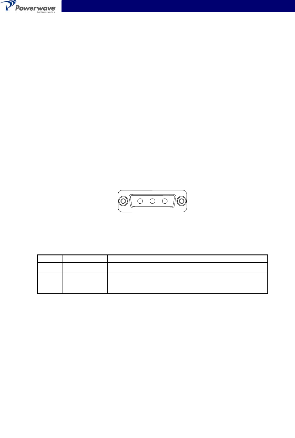
2-5 +27 VDC Power & Ground Connector
The +27 Vdc power and ground connections on the amplifier are made through a 3-pin female D-
Sub connector (figure 2-1) and are listed and described in table 2-1.
3 2 1
Figure 2-1 +27 Vdc Power & Ground Connector
Table 2-1 +27 Vdc Power & Ground Connector Descriptions
Pin Signal Description
1 Open
2 +27V +27 Vdc
3 RTN +27 Vdc return
Copyright Powerwave Technologies, Inc., October 2002. All rights reserved
2-2 October 2002

SPA9329-35 Installation & Service Manual
Section 3 Operating Instructions
3-1 Introduction
This section contains operating instructions for the SPA9329-35 power booster amplifier.
3-2 Initial Start-Up & Operating Procedures
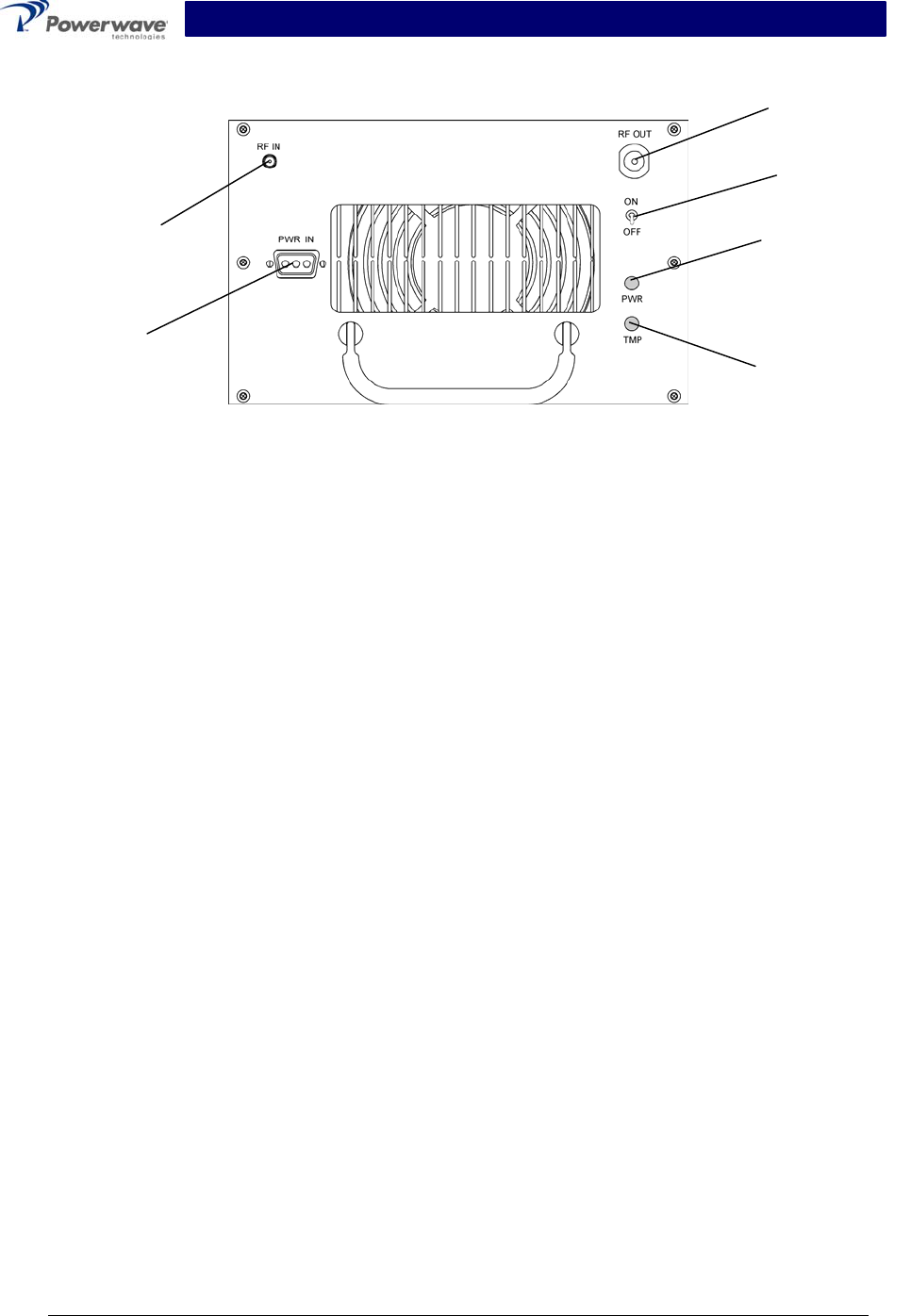
Operating controls, indicators, and connectors located on the SPA9329-35 booster amplifier
module are listed in table 3-1 and corresponding locations for each are shown in figure 3-1. To
perform the initial start-up, proceed as follows:
1. Verify that all power and RF input and output cables are properly connected, per section 2.
CAUTION
Before applying power, make sure that the input and output of the amplifier are prop-
erly terminated at 50 ohms. Do not operate the amplifier without a load attached. Re-
fer to table 1-2 for input power requirements. Excessive input power may damage the
amplifier.
NOTE
The output coaxial cable between the amplifier and the antenna must be 50-ohm co-
axial cable. Use of any other cable will distort the output.
2. Turn on supply that provides +27 Vdc to the amplifier system.
3. Set the DC power ON–OFF switch to ON. The corresponding PWR and TMP LED indicators
should illuminate.
4. Apply the RF input signal.
Table 3-1 SPA9329-35 Controls, Indicators, and Connectors
Function Description
RF IN RF channel input connector
RF OUT RF output connector
PWR IN +27 VDC power input connector
ON–OFF ON–OFF switch. Applies DC power to channel
amplifier
PWR LED indicator – Illuminates when correspond-
ing ON–OFF switch is set to ON
TMP LED indicator – Illuminates when correspond-
ing ON–OFF switch is set to ON. Goes out if
amplifier overheats or VSWR is high.
Copyright Powerwave Technologies, Inc., October 2002. All rights reserved
3-1 October 2002
SPA9329-35 Installation & Service Manual
Channel DC
Power ON –
OFF Switch
DC Power
Indicator
RF
Output
RF Input
+27 VDC
Input
A
mplifier En-
able/Disable
Indicator
Figure 3-1 SPA9329-35 Controls, Indicators, and Connector Locations
Copyright Powerwave Technologies, Inc., October 2002. All rights reserved
3-2 October 2002
SPA9329-35 Installation & Service Manual
Section 4 Principles of Operation
4-1 Introduction
This section contains a functional description of the SPA9329-35 power booster amplifier.
4-2 RF Input Signal
The maximum input power should not exceed the limits specified in table 1-1.
4-3 RF Output Load
The load impedance should be as good as possible (1.5:1 or better) in the working band for good
power transfer to the load.
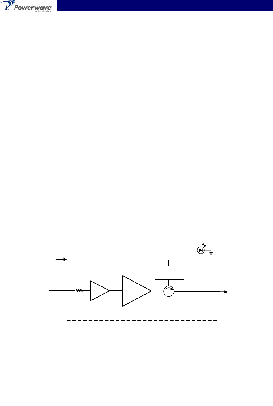
4-4 Amplifier Functional Description
The SPA9329-35 power booster amplifier, shown in figure 4-1, operates in the 1930 MHz to
1990 MHz range. The operating band is determined by the operating frequency selection(s) of
the base station (refer to table 1-2). The amplifier module consists of a single carrier amplifier pal-
let with the necessary combining and filtering to produce up to 100 watts (50 dBm) of output
power with a maximum gain of 23 dB. The amplifier employs a class AB amplifier for maximum
efficiency. The amplifier operates on +27 Vdc.
The amplifier is compliant to the requirements of FCC Part 24 with respect to spurious emissions
(see table 1-2). All gain variations, for example those due to temperature, are reduced to the pas-
sive reference variations.
RF In RF Out
Reverse
Detector
Comparator
and Alarm
Circuit
SPA9329-35
+27 VDC
TMP
Pre-Amp
Main
Amplifier
Figure 4-1 SPA9329-35 Booster Amplifier Block Diagram
4-5 Amplifier Module Cooling
Each amplifier module is cooled using a rear-mounted fan circulating air flow across the amplifier
heat sinks, the air then exits out the front of the module. This provides sufficient cooling to main-
tain the amplifier within the specified operating temperature range.
Copyright Powerwave Technologies, Inc., October 2002. All rights reserved
4-1 October 2002

SPA9329-35 Installation & Service Manual
4-6 Power Distribution
Primary DC power for the amplifier is provided by the host system. The amplifier generates all the
required voltages internally from the main source.
Copyright Powerwave Technologies, Inc., October 2002. All rights reserved
4-2 October 2002

SPA9329-35 Installation & Service Manual
Section 5 Maintenance
5-1 Introduction
This section contains periodic maintenance and performance test procedures for the SPA9329-
35 power booster amplifier. It also contains a list of test equipment required to perform the
identified tasks.
NOTE
Check your sales order and equipment warranty before attempting to service or re-
pair the unit. Do not break the seals on equipment under warranty or the warranty
will be null and void. Do not return equipment for warranty or repair service until
proper shipping instructions are received from the factory.
5-2 Periodic Maintenance
Periodic maintenance requirements are listed in table 5-1. Table 5-1 also lists the intervals at
which the tasks should be performed.
Table 5-1 Periodic Maintenance
Task Interval Action
Inspection
Cables & Connectors 12 Months Inspect signal and power cables for frayed insulation.
Check RF connectors to be sure that they are tight.
Performance Tests No periodic maintenance is necessary beyond that
recommended by the base station manufacturer.
5-3 Module Field Replacement
The SPA9329-35 power booster amplifier module can be replaced in the field on site by a
qualified technician with adequate ESD protection and experience maintaining RF power amplifi-
ers and similar equipment.
To replace a power amplifier module, proceed as follows:
1. Set the amplifier module DC power ON–OFF switch to OFF.
2. Disconnect the DC power cable from the amplifier module.
3. Disconnect the RF IN cable.
4. Disconnect the RF OUT cable.
5. Carefully remove the amplifier module.
6. Install replacement in reverse order.
Copyright Powerwave Technologies, Inc., October 2002. All rights reserved
5-1 October 2002

SPA9329-35 Installation & Service Manual
Section 6 Troubleshooting
6-1 Introduction
This section contains a list of problems and a few suggested actions that may correct any prob-
lem with the SPA9329-35 power booster amplifier. If the suggested corrective action does not
eliminate the problem, please contact your Powerwave field representative or the factory for fur-
ther instructions.
NOTE
Check your sales order and equipment warranty before attempting to service or re-
pair the unit. Do not break the seals on equipment under warranty or the warranty
will be null and void. Do not return equipment for warranty or repair service until
proper shipping instructions are received from the factory.
6-2 Troubleshooting
Refer to table 6-1 for troubleshooting suggestions.
Table 6-1 Troubleshooting
Symptom Suggested Action
Amplifier Module Inoperative Check for proper power supply voltage and that power input
connector is properly seated in mating connector.
Amplifier Module Not Enabled Check that the module ON–OFF power switch is set to the
ON position.
TMP Indicator Not Illuminated Verify input RF is within specified power and frequency limits.
Check that the cooling fan is operating.
6-3 Return For Service Procedures
When returning products to Powerwave, the following procedures will ensure optimum response.
6-3.1 Obtaining An RMA
A Return Material Authorization (RMA) number must be obtained prior to returning equipment to
the factory for service. Please contact our Repair Department at (888) 797-9283 or (714) 466-
1000 to obtain this number, or FAX your request to (714) 466-5816. Failure to obtain this RMA
number may result in delays in receiving repair service.
6-3.2 Repackaging For Shipment
To ensure safe shipment of the amplifier, it is recommended that the package designed for the
amplifier be used. The original packaging material is reusable. If it is not available, contact
Powerwave’s Customer Service Department for packing materials and information.
Copyright Powerwave Technologies, Inc., October 2002. All rights reserved
6-1 October 2002