Powerwave Technologies 5JS0062 GSM/EDGE Booster Amplifier, SPA9329-35N User Manual PAF 0850 001
Powerwave Technologies Inc GSM/EDGE Booster Amplifier, SPA9329-35N PAF 0850 001
Contents
- 1. Manual
- 2. User Manual
User Manual
1930-1990 MHz
Installation and Service
Manual
Model SPA9329-35N
2-Channel Booster Power Amplifier
Copyright Powerwave Technologies, Inc., July 2003. All rights reserved
044-05125 Rev. B July 2003
PRELIMINARY

SPA9329-35N Installation & Service Manual
July 2003
© 2003 Powerwave Technologies Incorporated. All rights reserved.
Powerwave Technologies, and the Powerwave logo are registered trademarks
Powerwave Technologies, Inc. reserves the right to make changes to the documentation and
equipment, including but not limited to component substitution and circuitry changes. Changes that
impact this manual may subsequently be incorporated in a later revision of this manual.
Powerwave Technologies, Inc. Tel: (714) 466-1000
1801 East St. Andrew Place (888) 797-9283
Santa Ana, CA 92705 Fax: (714) 466-5800
Web Site: www.powerwave.com
Copyright Powerwave Technologies, Inc., July 2003. All rights reserved
044-05125 Rev. B ii July 2003
PRELIMINARY
SPA9329-35N Installation & Service Manual
Section 1 General Description
1-1 Introduction
This manual contains information and procedures for installation, operation, and maintenance of
Powerwave’s model SPA9329-35N Two-Channel Power Booster Amplifier module. The manual
is organized into six sections as follows:
Section 1. General Description
Section 2. Installation
Section 3. Operating Instructions
Section 4. Principles of Operation
Section 5. Maintenance
Section 6. Troubleshooting
1-2 General Description
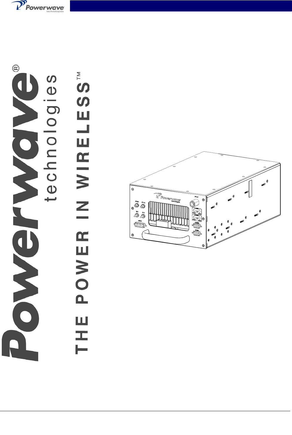
The SPA9329-35N is a linear, two-channel booster amplifier that operates in a bandwidth of 60
MHz from 1930 MHz to 1990 MHz providing 35 watts (45.5 dBm) per channel at the combiner
output port with a nominal gain of 21 dB total gain. The amplifier is modular in design, and ideally
suited for use in GSM base stations.
The amplifier, shown in figures 1-1 through 1-4, has a power input, two RF inputs, and one RF
output. Controls and indicators consist of a DC power switch for each channel, corresponding
LED power indicators, and alarm LED indicators (see section 3, table 3-1). Primary power for op-
erating the amplifier is -48 VDC. Each amplifier module has a fan assembly contained in the rear
of the module, as shown in figures 1-2, to provide cooling. Air is drawn through the front of the
amplifier, over the internal heat sinks, and then exhausted by the fan.
1-3 Ordering Information
Table 1-1 lists major system component numbers and descriptions for use in ordering booster
amplifiers or components.
Table 1-1 Major System Components
Component
Number
Description
SPA9329-35N 35-Watt Amplifier, -48 VDC
NOTE
A quality transmit filter or duplexer must be installed after this amplifier to ensure FCC
Type Acceptance of the amplifier. The filter/duplexer should be rated for at least 200
Watts average power and 800 Watts instantaneous power (minimum).
Copyright Powerwave Technologies, Inc., July 2003. All rights reserved
044-05125 Rev. B 1-1 July 2003
PRELIMINARY
SPA9329-35N Installation & Service Manual
Functional & Physical Specifications
Functional and physical specifications for the SPA9329-35N amplifier are listed in table 1-2.
Table 1-2 SPA9329-35N Booster Amplifier Functional Specifications
Frequency Range 1930-1990 MHz
Carrier Spacing (center to
center) 200 kHz nominal
Occupied Bandwidth 200 kHz/carrier
Max Power Output per Car-
rier 35 Watts (45.5 dBm)
Module Gain per Input 21 dB typical
Tx Input Level (per Input)
for 35 Watts 10 mW (+10 dBm) to 10 Watts (+30 dBm)
Gain Flatness Across
20 MHz Band ≤ 0.5 dB Peak to Peak
IMD Performance -65 dBc maximum with two CW tones (one for each channel) unmodu-
lated @35 watts/tone
Operating Voltage -38 VDC to –58 VDC
Operating Current (per In-
put Connector X2) 16 Amps @ -48 VDC (typical)
Inrush Current (Peak) 40 Amps Maximum
Operating Temperature: 0 ºC to +50 ºC
Tx Input Connector SMA-F x 2 (One per Input)
Tx Output Connector Type ‘N’ Female
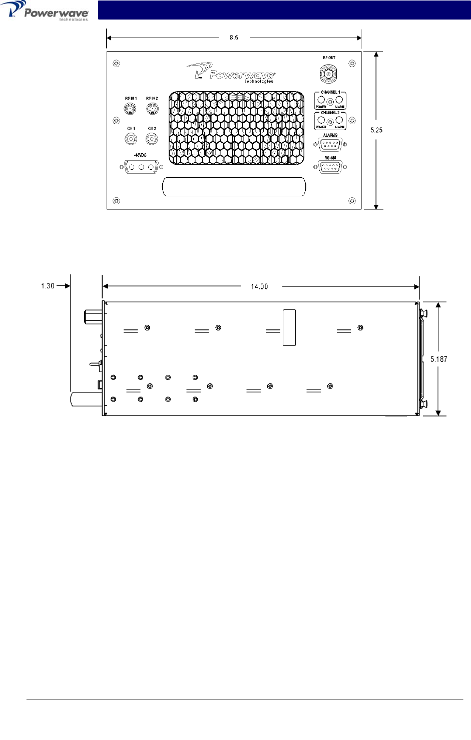
Dimensions (+27 VDC
Model) 5.25”H x 8.50”W x 15.30”D including handle
Mounting Options 19”, 23”, or 24” Relay Rack Mounted or Outdoor Enclosure Mounted
Weight 25 lbs
Copyright Powerwave Technologies, Inc., July 2003. All rights reserved
044-05125 Rev. B 1-2 July 2003
PRELIMINARY
SPA9329-35N Installation & Service Manual
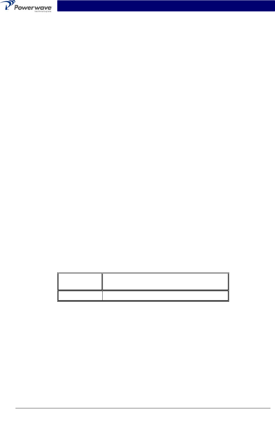
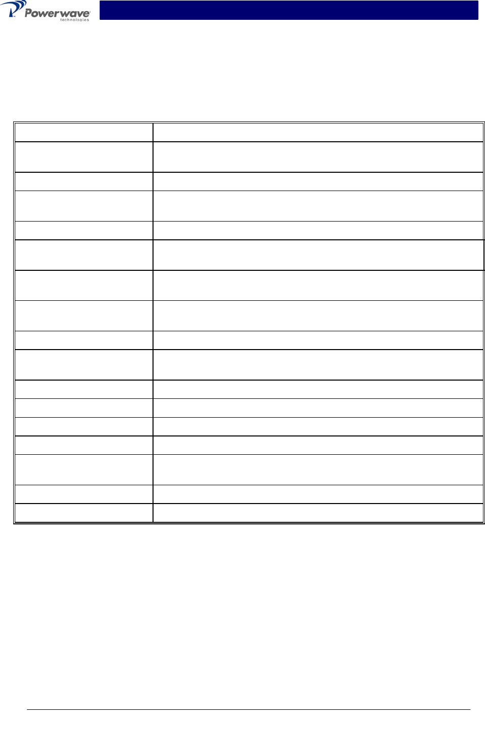
Figure 1-1. SPA9329-35N Front Isometric View
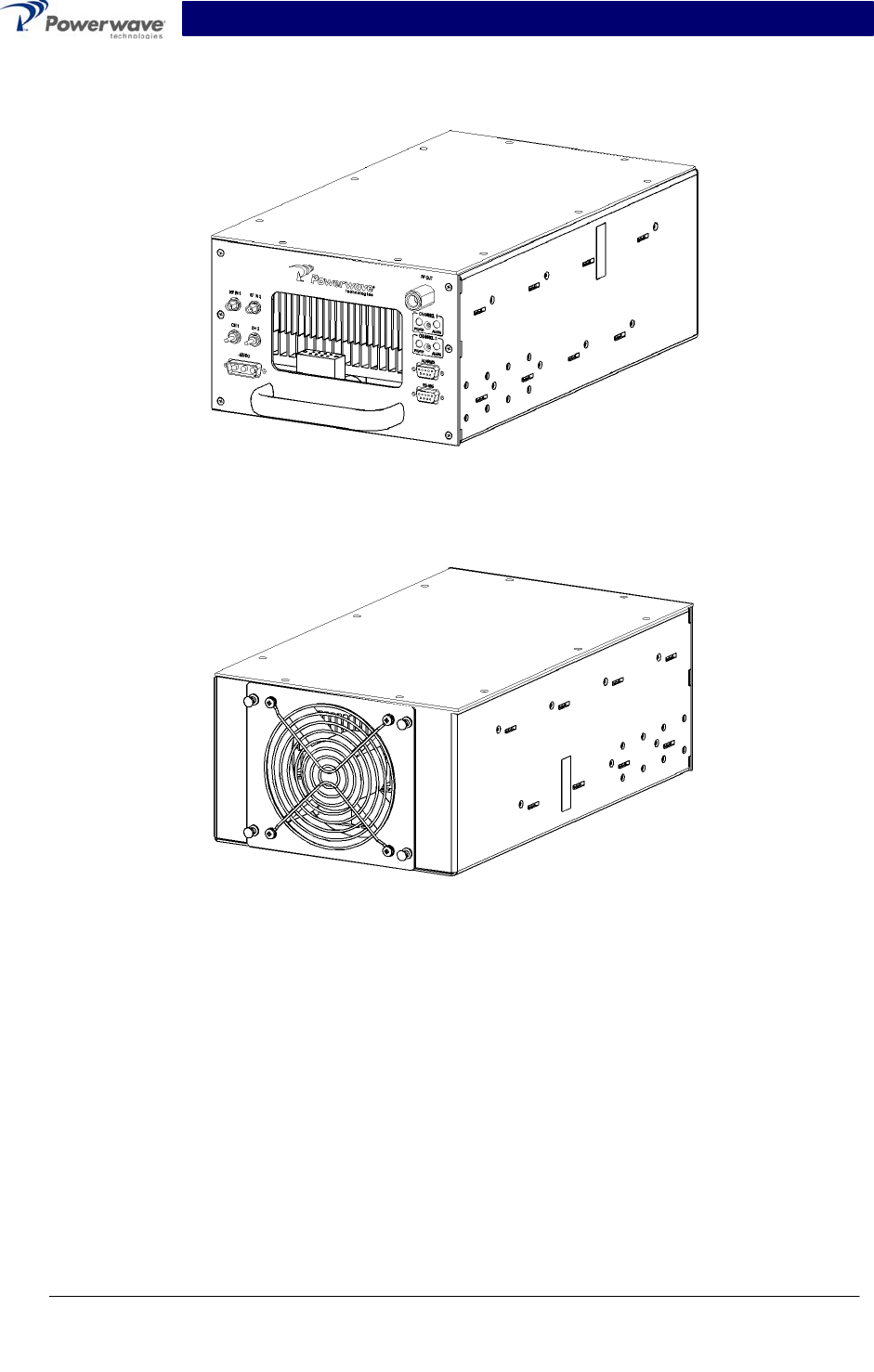
Figure 1-2. SPA9329-35N Rear Isometric View
Copyright Powerwave Technologies, Inc., July 2003. All rights reserved
044-05125 Rev. B 1-3 July 2003
PRELIMINARY
SPA9329-35N Installation & Service Manual
Figure 1-3. SPA9328-35N Front Panel
Figure 1-4. SPA9329-35N Side View
Copyright Powerwave Technologies, Inc., July 2003. All rights reserved
044-05125 Rev. B 1-4 July 2003
PRELIMINARY

SPA9329-35N Installation & Service Manual
Section 2 Installation
2-1 Introduction
This section contains unpacking, inspection, and installation instructions and recommendations
for the Powerwave model SPA9329-35N Two-Channel Power Booster Amplifier module. Care-
fully read all material in this section prior to equipment unpacking or installation. Also read and
review the operating procedures in section 3 prior to installing the equipment. It is important that
the licensee perform these tasks correctly. If applicable, carefully read the appropriate parts of
the Federal Communications Commission (FCC) rules to determine how they apply to your instal-
lation. DON'T TAKE CHANCES WITH YOUR LICENSE.
2-2 Electrical Service Recommendations
Powerwave Technologies recommends that proper AC line conditioning and surge suppression
be provided on the primary AC input. All electrical service should be installed in accordance with
the National Electrical Code, any applicable state or local codes, and good engineering practice.
Special consideration should be given to lightning protection of all systems in view of the vulner-
ability of most transmitter sites to lightning. Lightning arrestors are recommended in the service
entrance. Straight, short ground runs are recommended. The electrical service must be well
grounded.
Each amplifier system should have its own circuit breaker, so a failure in one does not shut off
the whole installation. Circuit breakers should be thermal type, capable of handling the maximum
anticipated inrush current, in a load center with a master switch.
2-3 Unpacking & Inspection
This equipment has been operated, tested, and calibrated at the factory. Carefully open the con-
tainer(s) and remove the amplifier module(s). Retain all packing material that can be reassem-
bled in the event that the unit must be returned to the factory.
CAUTION
Exercise care in handling equipment during inspection to prevent damage caused by
rough or careless handling.
Visually inspect the amplifier module for damage that may have occurred during shipment. Check
for evidence of water damage, bent or warped chassis, loose screws or nuts, or extraneous pack-
ing material in the connector. If the equipment is damaged, a claim should be filed with the carrier
once the extent of any damage is assessed. We cannot stress too strongly the importance of
IMMEDIATE careful inspection of the equipment and the subsequent IMMEDIATE filing of the
necessary claims against the carrier if necessary. If possible, inspect the equipment in the pres-
ence of the delivery person. If the equipment is damaged, the carrier is your first area of re-
course. If the equipment is damaged and must be returned to the factory, write or phone for a re-
turn authorization (see paragraph 6.3). Powerwave may not accept returns without a return au-
thorization. Claims for loss or damage may not be withheld from any payment to Powerwave, nor
may any payment due be withheld pending the outcome thereof. WE CANNOT GUARANTEE
THE FREIGHT CARRIER'S PERFORMANCE
Copyright Powerwave Technologies, Inc., July 2003. All rights reserved
044-05125 Rev. B 2-1 July 2003
PRELIMINARY
SPA9329-35N Installation & Service Manual
2-4 Installation Instructions
The SPA9329-35N booster amplifier module is designed for installation in enclosures that permit
access to the front of the module for connection of RF cables and the power connectors (refer to
paragraphs 2-5, and 2-6 for connector descriptions).
WARNING
Turn external primary DC power off before connecting any cables.
1. Connect the power source to the booster amplifier power input connector (see figure 2-1, 3-
1, and table 2-1). Do not apply power at this time.
2. Connect the RF input cable(s) to the RF IN connector(s).
3. Connect an RF cable from the RF OUT (Type-N) to the transmit filter input.
CAUTION
It is highly recommended that the output of the SPA9329-35N Booster Amplifier be fed
through an appropriate bandpass transmit filter prior to the transmit antenna input.
4. Connect the antenna cable to the RF filter output connector.
5. Refer to section 3 for initial turn-on and checkout procedures.
2-5 RF Connectors
The amplifier has two SMA female RF IN connectors and one RF OUT connector (refer to figure
3-1 for locations). The input power to the RF IN connectors should not exceed the level specified
in table 1-2. The RF OUT connector is Type-N female.
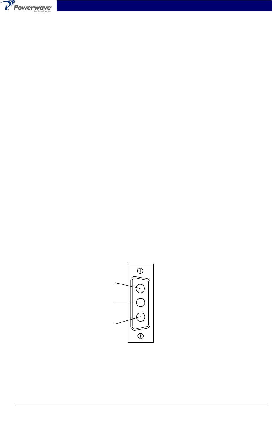
2-6 -48 VDC Power and Ground Connector
The -48 Vdc power and ground connections on the amplifier are made through a 3-pin female D-
Sub connector (figure 2-1). Each pin and signal is listed and described in table 2-1.
1
2
3
Figure 2-1 -48 Vdc Power and Ground Connector
Copyright Powerwave Technologies, Inc., July 2003. All rights reserved
044-05125 Rev. B 2-2 July 2003
PRELIMINARY
SPA9329-35N Installation & Service Manual
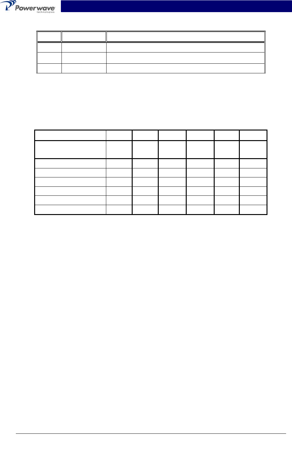
Table 2-1 -48 Vdc Power and Ground Connector Pin Descriptions
Pin Signal Description
1 Open Not Used
2 -48 Vdc -48 Vdc
3 Return DC Return
2-7 SPA9329-35N Alarm Connections
Alarm connections are defined for the SPA9329-35N booster amplifier modules in table 2-2.
Table 2-2 Alarm Connector Definitions
Pin Number 1 2 3 6 7 8
Contact Point With
Respect To Common NO C NC NO C NC
Amp 1 No Alarm Open C Closed Open C Closed
Amp 1 Alarm Closed C Open Closed C Open
Amp 1 DC Off Closed C Open Closed C Open
Amp 2 No Alarm Open C Closed Open C Closed
Amp 2 Alarm Closed C Open Closed C Open
Amp 2 DC Off Closed C Open Closed C Open
Copyright Powerwave Technologies, Inc., July 2003. All rights reserved
044-05125 Rev. B 2-3 July 2003
PRELIMINARY
SPA9329-35N Installation & Service Manual
Section 3 Operating Instructions
3-1 Introduction
This section contains operating instructions for the SPA9329-35N Two-Channel Power Booster
Amplifier module.
3-2 Initial Start-Up and Operating Procedures
Operating controls, indicators, and connectors located on the SPA9329-35N booster amplifier
module are listed in table 3-1 and corresponding locations for each are shown in figure 3-1. To
perform the initial start-up, proceed as follows:
1. Verify that all power and RF input and output cables are properly connected as described in
section 2.
CAUTION
Before applying power, make sure that the input and output of the amplifier are prop-
erly terminated at 50 ohms. Do not operate the amplifier without a load attached. Re-
fer to table 1-2 for input power requirements. Excessive input power may damage the
amplifier.
NOTE
The output coaxial cable between the amplifier and the antenna must be 50-ohm. Use
of any other cable will distort the output.
2. Set the power ON–OFF switch to ON. The corresponding PWR and ALARM LED indicators
should illuminate.
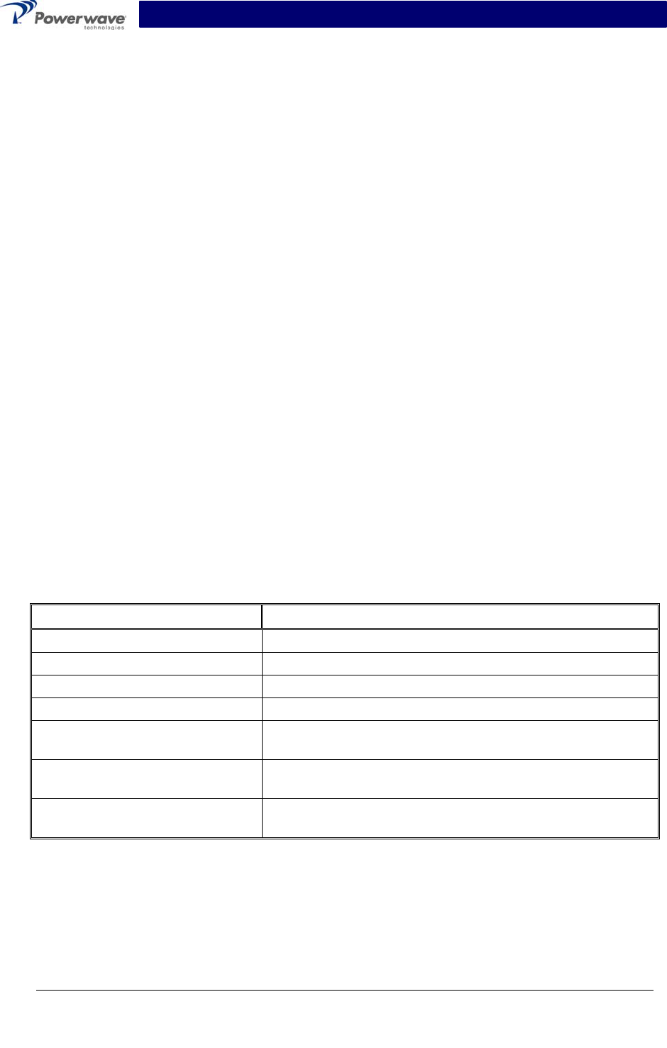
Table 3-1 SPA9329-35N Controls, Indicators, and Connectors
Function Description
RF IN (2) RF channel input connectors
RF OUT (1) RF output connector
PWR IN -48 VDC power input connector
ON–OFF ON–OFF switches. Apply DC power to amplifier channel
PWR LED indicators – Illuminates when corresponding amplifier
channel ON–OFF switch is set to ON
ALARM LED indicators – Illuminates when corresponding amplifier
channel disables because of an alarm.
ALARMS Connector Alarms cable interface connector (see section 2 for defini-
tions).
Copyright Powerwave Technologies, Inc., July 2003. All rights reserved
044-05125 Rev. B 3-1 July 2003
PRELIMINARY
SPA9329-35N Installation & Service Manual
DC Power
ON/OFF
Switches
A
larms
Connector
Power and
A
larm LEDs
RF
Inputs
RF
Out
p
ut
Primary
Power
Input
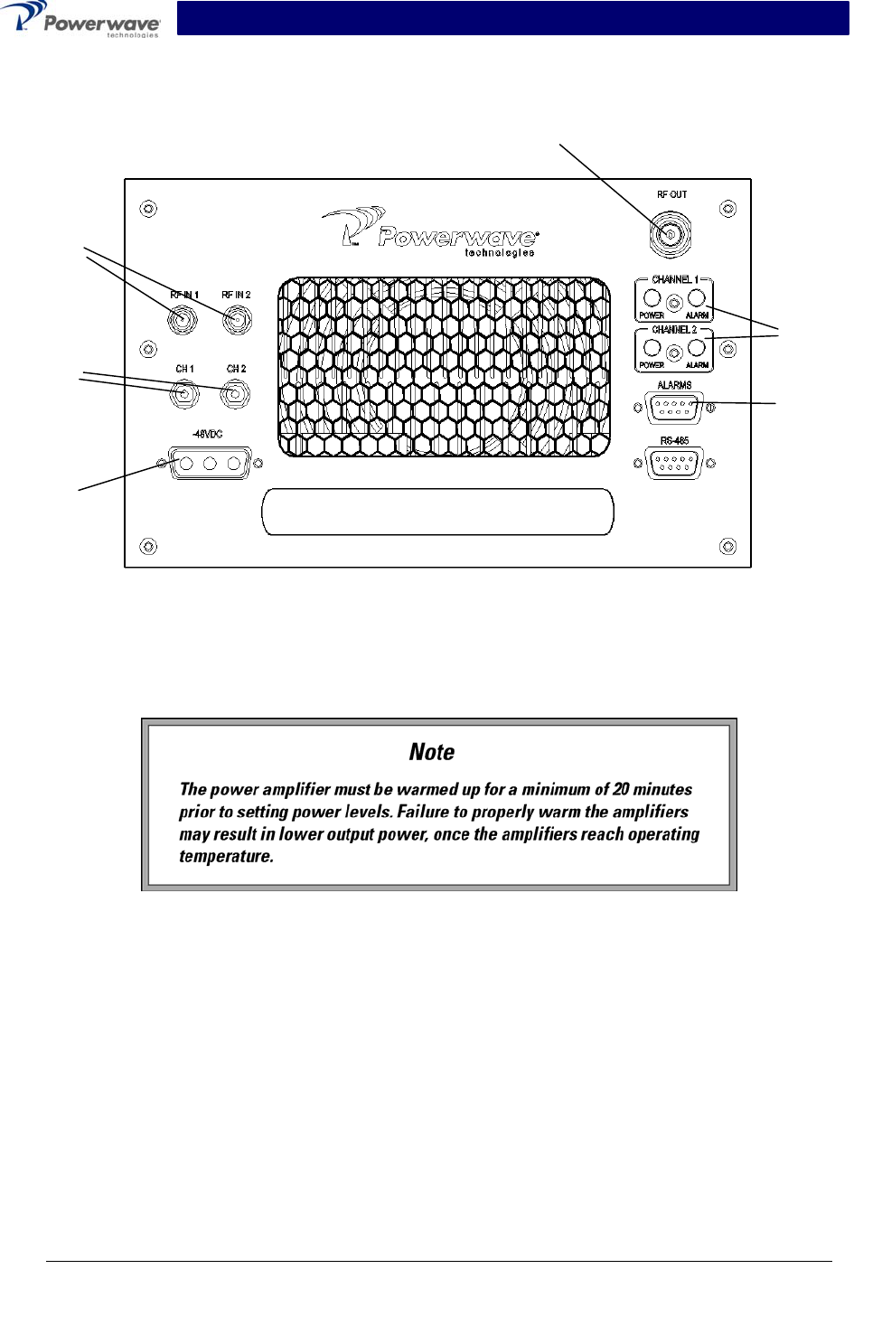
Figure 3-1 SPA9329-35N Controls, Indicators, and Connector Locations
3-3 Power Setting Procedure
WARNING
Turn the amplifier off when disconnecting and moving amplifier RF cables. Never re-
move or install coaxial cables on either the input or output port when the power am-
plifier is turned on. Operating the power amplifier while disconnecting and connecting
RF cables may damage the equipment and/or cause personal injury.
A simplified power-setting example is shown in figure 3-2.
Copyright Powerwave Technologies, Inc., July 2003. All rights reserved
044-05125 Rev. B 3-2 July 2003
PRELIMINARY

SPA9329-35N Installation & Service Manual
Filter
SCPA
(+21 dB)
+10 dBm to +30 dBm
10 m W to 10 W
35 W
45.5 dBm
Figure 3-2 Gain Example Block Diagram
1. Turn on external exciter/transceiver and apply RF input signal. Adjust the input power to
achieve the desired output power (refer to table 1-2).
Copyright Powerwave Technologies, Inc., July 2003. All rights reserved
044-05125 Rev. B 3-3 July 2003
PRELIMINARY
SPA9329-35N Installation & Service Manual
Section 4 Principles of Operation
4-1 Introduction
This section contains functional descriptions for the SPA9329-35N Two-Channel Power Booster
Amplifier module.
4-2 RF Input Signal
The maximum input power should not exceed the limits specified in table 1-2.
4-3 RF Output Load
The load impedance should be as good as possible (VSWR ≤1.5:1) in the operating band for
good power transfer to the load.
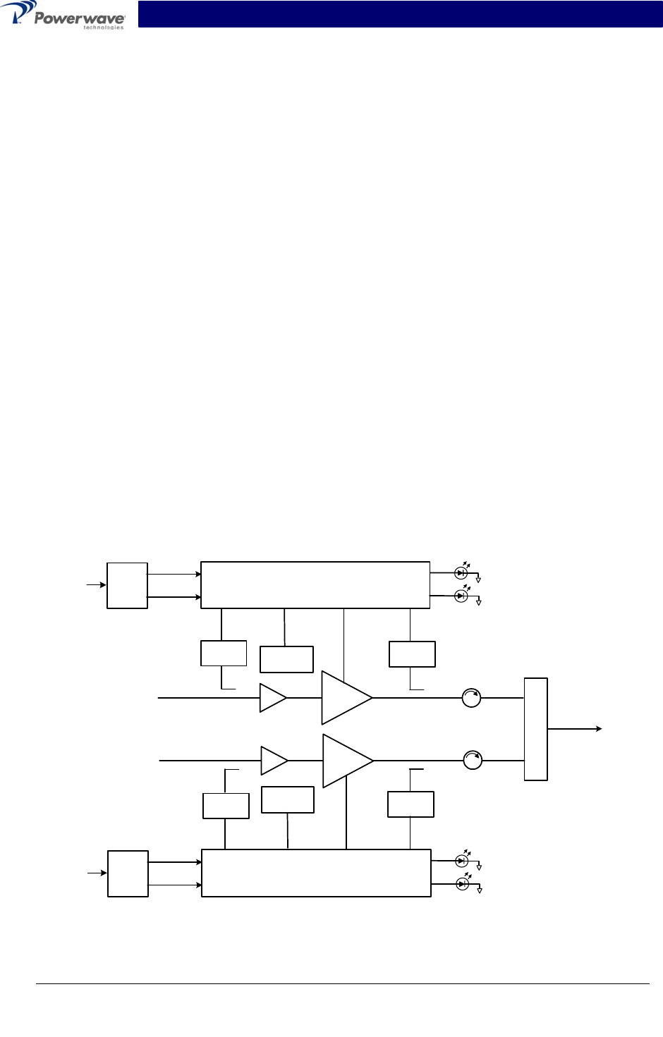
4-4 Amplifier Functional Description
The SPA9329-35N power booster amplifier, shown in figure 4-1, operates in the 1930 MHz to
1990 MHz range. The operating band is determined by the operating frequency selection(s) of
the base station (refer to tables 1-2 and 1-3). The amplifier module consists of two single-carrier
amplifier pallets with necessary combining and filtering to produce up to 35 watts (45.5 dBm) of
output power with a typical gain of 21 dB. The amplifier employs class AB bias for maximum effi-
ciency. The amplifier operates from a -48 Vdc power source.
The amplifier is compliant to requirements of FCC rules with respect to spurious emissions (see
tables 1-2 and 1-3). Most of the amplifier gain vs temperature variations are due to LDMOS tran-
sistor characteristics.
RF In
2:1
RF Out
-48 VDC
Pre-Amp
RF Power Control and LED Drivers
Input
Detector
Output
Detector
Temperature
Sensor
ALARM
PWR
+15 VDC
+5 VDC
RF Power Control and LED Drivers ALARM
PWR
+15 VDC
+5 VDC
RF In
Pre-Amp
Amplifier
Bias
Main
Amplifier
Main
Amplifier
Input
Detector
Output
Detector
Temperature
Sensor
-48 VDC
C
o
m
b
i
n
e
r
Amplifier
Bias
Voltage
Regulator
Voltage
Regulator
Figure 4-1 SPA9329-35N Booster Amplifier Block Diagram
Copyright Powerwave Technologies, Inc., July 2003. All rights reserved
044-05125 Rev. B 4-1 July 2003
PRELIMINARY

SPA9329-35N Installation & Service Manual
4-5 Amplifier Module Cooling
Each amplifier module is cooled using an enclosed rear-mounted fan circulating airflow across
the amplifier heat sinks. Air is pulled from the front of the module and exits at the rear. This pro-
vides sufficient cooling to maintain the amplifier within its safe operating temperature range.
4-6 Power Distribution
Primary DC power for the amplifier is provided by the host system. The amplifier generates all the
required voltages internally from the main source.
Copyright Powerwave Technologies, Inc., July 2003. All rights reserved
044-05125 Rev. B 4-2 July 2003
PRELIMINARY
SPA9329-35N Installation & Service Manual
Section 5 Maintenance
5-1 Introduction
This section contains periodic maintenance and field replacement procedures for the SPA9329-
35N Two-Channel Power Booster Amplifier module.
NOTE
Check your sales order and equipment warranty before attempting to service or re-
pair the unit. Do not break seals on equipment under warranty or the warranty will be
null and void. Do not return equipment for warranty or repair service until proper
shipping instructions are received from the factory.
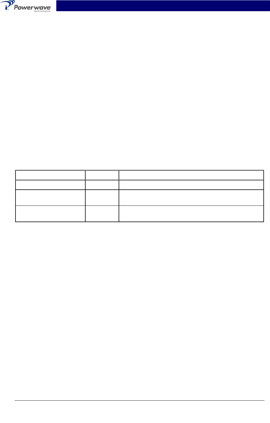
5-2 Periodic Maintenance
Periodic maintenance tasks, performance intervals, and the appropriate actions to be taken are
listed in table 5-1.
Table 5-1 Periodic Maintenance
Task Interval Action
Inspection:
Cables & Connectors 12 Months Inspect signal and power cables for frayed insulation.
Check RF connectors to be sure that they are tight.
Performance Tests No periodic maintenance is necessary beyond that
recommended by the base station manufacturer.
5-3 Module Field Replacement
The SPA9329-35N power booster amplifier modules can be replaced in the field on site by a
qualified technician with experience maintaining RF power amplifiers and similar equipment.
To replace a power amplifier module, proceed as follows:
1. Set the amplifier module DC power ON–OFF switches to OFF.
2. Disconnect the DC power cable from the amplifier module.
3. Disconnect the RF IN cables.
4. Disconnect the RF OUT cable.
5. Carefully remove the amplifier module.
6. Install replacement amplifier module in reverse order.
Copyright Powerwave Technologies, Inc., July 2003. All rights reserved
044-05125 Rev. B 5-1 July 2003
PRELIMINARY

SPA9329-35N Installation & Service Manual
Section 6 Troubleshooting
6-1 Introduction
This section contains a list of problems and suggested actions that may correct problems en-
countered with the SPA9329-35N Two-Channel Power Booster Amplifier module. If the sug-
gested corrective action does not eliminate the problem, please contact your Powerwave field
representative or the factory for further instructions.
NOTE
Check your sales order and equipment warranty before attempting to service or re-
pair the unit. Do not break the seals on equipment under warranty or the warranty will
be null and void. Do not return equipment for warranty or repair service until proper
shipping instructions are received from the factory.
6-2 Troubleshooting
Refer to table 6-1 for troubleshooting suggestions.
Table 6-1 Troubleshooting
Problem Suggested Corrective Action
Amplifier Module Inoperative Check for proper power supply voltage and that power input
connector is properly seated in mating connector.
Amplifier Module Not Enabled Check that the channel ON–OFF power switch is set to the
ON position.
6-3 Return For Service Procedures
When returning products to Powerwave, following the guidelines in the paragraphs that follow will
ensure optimum response.
6-3.1 Obtaining An RMA
A Return Material Authorization (RMA) number must be obtained prior to returning equipment to
the factory for service. Please contact our Repair Department at (888) 797-9283 or (714) 466-
1000 to obtain this number, or FAX your request to (714) 466-5816. Failure to obtain this RMA
number may result in delays in receiving repair service.
6-3.2 Repackaging For Shipment
To ensure safe shipment of the amplifier, it is recommended that the package designed for the
amplifier (original packaging material) be used for reshipment. If it is not available, contact
Powerwave’s Customer Service Department for the proper packing materials and information.
Copyright Powerwave Technologies, Inc., July 2003. All rights reserved
044-05125 Rev. B 6-1 July 2003
PRELIMINARY