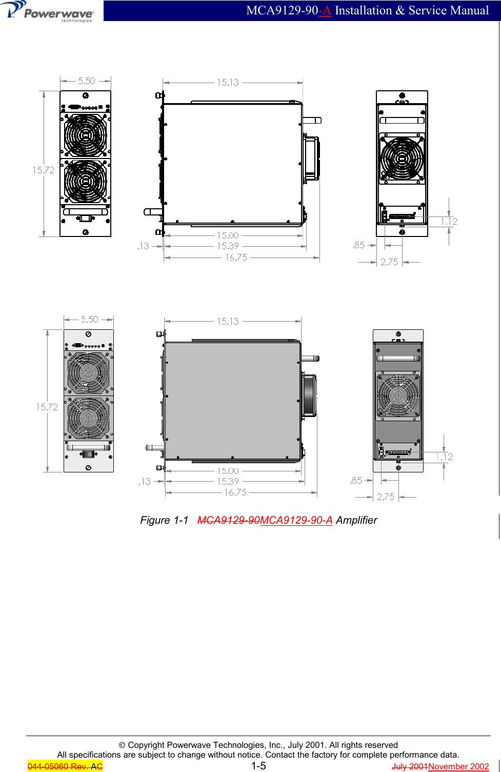
Powerwave Technologies 5JS0063 Amplifier, MCA9129-90-A User Manual Cobra manual Section 1

Powerwave Technologies Inc Amplifier, MCA9129-90-A Cobra manual Section 1

Manual

 MCA9129-90-A Installation & Service ManualÓ Copyright Powerwave Technologies, Inc., July 2001. All rights reservedAll specifications are subject to change without notice. Contact the factory for complete performance data.044-05060 Rev. AC1-1 July 2001November 2002Section 1  General Description1-1  IntroductionThis manual contains information and procedures for installation, operation, and maintenance ofPowerwave’s MCA9129-90MCA9129-90-A multicarrier cellular amplifier.  The manual is organ-ized into six sections as follows:Section 1. General DescriptionSection 2. InstallationSection 3. Operating InstructionsSection 4. Principles of OperationSection 5. MaintenanceSection 6 Troubleshooting1-2  General DescriptionThe MCA9129-90MCA9129-90-A (see figure 1-1) is a linear, feed-forward power amplifier thatoperates in the 25 MHz frequency band from 869 MHz to 894 MHz. The amplifier can simultane-ously transmit multiple frequencies, with better than -65 dBc third order intermodulation distortion(IMD) at 100 watts output, or –60 dBc IMD at 120 watts output. It is designed for use in an ampli-fier system that is modular in design, and is ideally suited for use in AMPS/TDMA/CDMA basestations. When used in a subrack employing four MCA9129-90MCA9129-90-A amplifiers, thesystem offers up to 360 watts output at–65dBc IMD performance level (430 watts output at –60dBc IMD). The plug-in Model MCA9129-90MCA9129-90-A amplifier modules can each provide 120 watts of power and function com-pletely independently of each other. The amplifier modules are designed for parallel operation toproduce high peak power output and backup redundancy for remote applications. All solid-state,the system is designed to provide trouble-free operation with minimum maintenance. The sys-tem's modular construction and unique and highly effective LED-based operational status andfault indicators help minimize downtime. The turn-on and turn-off sequences of voltages are fullyautomatic, as is overload protection and recycling. Inadvertent operator damage from front panelmanipulation is virtually impossible.Each amplifier module has a status connector that allows the host system to monitor the amplifiermodule performance. The front panel of each amplifier module has unit level status/fault indica-tors and an RF on/off/reset switch. Primary power for the amplifier is +27 Vdc. Cooling for eachplug-in amplifier module is provided by three fans, two mounted on the front and one on the rearof the module.  The fans draw outside air through the front of the module and exhaust hot air outthrough the rear of the module.1-3  Functional and Physical SpecificationsFunctional and physical specifications for the amplifier are listed in tables 1-2 and 1-3.1-4  Equipment ChangesPowerwave Technologies, Inc. reserves the right to make minor changes to the equipment, in-cluding but not necessarily limited to component substitution and circuitry changes. Changes thatimpact this manual may subsequently be incorporated in a later revision of this manual. To thatend, we ask that you, our customer, share with us any information acquired in field situations thatwould enhance this manual.
 MCA9129-90-A Installation & Service ManualÓ Copyright Powerwave Technologies, Inc., July 2001. All rights reservedAll specifications are subject to change without notice. Contact the factory for complete performance data.044-05060 Rev. AC1-2 July 2001November 20021-5  Ordering InformationTable 1-1 following gives the part numbers and descriptions to be used when ordering either anentire amplifier or replacement fans.Table 1-1   Major Amplifier ComponentsModel Number DescriptionMCA9129-90MCA9129-90-A100 W 869-894 MHz MCPA Module.800-01024-001800-01779-001Front fan assembly, large.800-01025-001800-01779-002Front Rear fan assembly, small800-00781-002 Rear fan assembly. NOTEA quality transmit filter or duplexer must be installed after this amplifier to ensureFCC Type Acceptance of the amplifier. The filter/duplexer should be rated for at least500 Watts average power and 5000 Watts instaneous power (minimum) when fouramplifiers per subrack are installed.Table 1-2   MCA9129-90MCA9129-90-A Multicarrier Cellular Amplifier FunctionalSpecifications, 100 WattsFrequency Range 869-894 MHz (25 MHz Bandwidth)Total Maximum Input Power -12 dBmTotal Output Power 100 W typical (1 Module)BTUs @ 100 W 3813Intermodulation Distortionand In-Band Spurious:-65 dBc (Min) @ +24  +26 to +28 Vdc @ 100 Watts(-55 dBc (Min) @ +23 to + 24 Vdc)RF Gain at 880 MHz 62 dBGain Flatness: ± 0.7 dB @ 27 Vdc ±1 VdcGain Variation Over Temperature: ±0.3 dB from 23 to 30 VdcOutput Protection: Mismatch ProtectedInput Port Return Loss: -14 dB (Min)Harmonics: Better than -50 dBcOut of Band Spurious: Better than -60 dBcDuty Cycle: ContinuousDC Input Power: +27 Vdc ± 1 Vdc, 45 36 Amps Max @ 100 WattsOperational +21 Vdc to 30 VdcOperating Temperature: 0 ºC. to +50 ºC.Storage Temperature: -40 ºC. to +85 ºC.Operating Humidity: 5 % - 95 % Relative Humidity (Noncondensing)Storage Humidity: 5 % - 95 % Relative Humidity (Noncondensing)DC Input, Summary Alarm, and RFInput / Output Connectors:21-Pin D-Subminiature Combo Connector plus single-pin D-Sub connector for additional DC capability.Weight 45 poundsDimensions: 15.72” (9U) High, 5.50” Wide, 17.1116.75” Deep
 MCA9129-90-A Installation & Service ManualÓ Copyright Powerwave Technologies, Inc., July 2001. All rights reservedAll specifications are subject to change without notice. Contact the factory for complete performance data.044-05060 Rev. AC1-3 July 2001November 2002
 MCA9129-90-A Installation & Service ManualÓ Copyright Powerwave Technologies, Inc., July 2001. All rights reservedAll specifications are subject to change without notice. Contact the factory for complete performance data.044-05060 Rev. AC1-4 July 2001November 2002NOTEA quality transmit filter or duplexer must be installed after this amplifier to ensureFCC Type Acceptance of the amplifier. The filter/duplexer should be rated for at least500 Watts average power and 5000 Watts instaneous power (minimum) when fouramplifiers per subrack are installed.Table 1-3   MCA9129-90MCA9129-90-A Multicarrier Cellular Amplifier (FCC Tested @ 120Watts)Frequency Range 869-894 MHz (25 MHz Bandwidth)Total Maximum Input Power -11   -11.2dBmTotal Output Power 120 W typical (1 Module)BTUs @ 120 W 4381Intermodulation Distortionand In-Band Spurious:-60 dBc (MinMax) @ +24 +26 to +28 Vdc @ 120 Watts(-55 dBc (Min) @ +23 to + 24 Vdc)RF Gain at 880 MHz 62 dBGain Flatness: ± 0.7 dB @ 27 Vdc ±1 VdcGain Variation Over Temperature: ±0.3 dB from 23 to 30 VdcOutput Protection: Mismatch ProtectedInput Port Return Loss: -14 dB (Min)Harmonics: Better than -50 dBcOut of Band Spurious: Better than -60 dBcDuty Cycle: ContinuousDC Input Power: +27 Vdc ± 1 Vdc, 52  40 Amps Max @ 120 WattsOperational +21 Vdc to 30 VdcOperating Temperature: 5  0ºC. to +40 ºC.Storage Temperature: -40 ºC. to +85 ºC.Operating Humidity: 5 % - 95 % Relative Humidity (Noncondensing)Storage Humidity: 5 % - 95 % Relative Humidity (Noncondensing)DC Input, Summary Alarm, and RFInput / Output Connectors:21-Pin D-Subminiature Combo Connector plus single-pin D-Sub connector for additional DC capability.Weight 45 poundsDimensions: 15.72” (9U) High, 5.50” Wide, 17.1116.75” Deep
 MCA9129-90-A Installation & Service ManualÓ Copyright Powerwave Technologies, Inc., July 2001. All rights reservedAll specifications are subject to change without notice. Contact the factory for complete performance data.044-05060 Rev. AC1-5 July 2001November 2002Figure 1-1   MCA9129-90MCA9129-90-A Amplifier
 MCA9129-90-A Installation & Service ManualÓ Copyright Powerwave Technologies, Inc., July 2001. All rights reserved044-05060 Rev. C 2-1 July 2001November 2002Section 2  Installation2-1  IntroductionThis section contains unpacking, inspection, and installation instructions / recommendations forthe model MCA9129-90MCA9129-90-A multicarrier cellular amplifier.  It is important that the li-censee perform the following tasks correctly and in good faith:1.  Carefully read all material in this section prior to equipment unpacking or installation.2.  Also, read and review the operating procedures in Section 3 prior to installing the equipment.3.  If applicable, carefully review the Federal Communications Commission (FCC) rules as theyapply to your installation.  DON'T TAKE CHANCES WITH YOUR LICENSE.2-2  Site SurveyPowerwave Technologies recommends that site surveys be performed by qualified individuals orfirms prior to equipment ordering or installation. Performing a detailed site survey will reduce oreliminate installation and turn-up delays caused by oversights. A general site survey form is pro-vided in Appendix A. This form is commonly used by Powerwave Field Engineers and may beused as a guide. Pay particular attention to power plant capacity, air conditioning needs, floorspace, and RF/DC cabling/breaker requirements.2-3  Electrical Service RecommendationsPowerwave Technologies recommends that proper AC line conditioning and surge suppressionbe provided on the primary AC input to the +27 Vdc power source.  All electrical service should beinstalled in accordance with the National Electrical Code, any applicable state or local codes, andgood engineering practice.  Special consideration should be given to lightning protection of allsystems in view of the vulnerability of most transmitter sites to lightning.  Lightning arrestors arerecommended in the service entrance.  Straight, short ground runs are recommended.  The elec-trical service must be well grounded.Each amplifier system should have its own circuit breaker (70-amp minimum), so a failure in onedoes not shut off the whole installation.  Circuit breakers should be thermal type, capable of han-dling the anticipated inrush current, in a load center with a master switch.  See table 2-1.A typical three-sector site will utilize three MCR4109-1 amplifier subracks, each housing up to fourMCA9129-90MCA9129-90-A amplifiers. The power plant should be able to support the 540 amps432 amps of current required by this equipment, plus the remaining base station equipment. Apower plant of less than 800 amps is probably not sufficient. Since all the amplifiers are not run-ning at full capacity at the same time in normal operation, table 2-1 describes the current load fora 3 sector (70%), 2 sector (80%) and omni (90%) site. Based on this table, an 800 amp powerplant may suffice.Battery backup or UPS systems should be installed in remote sites or in sites which experiencebrownout conditions or generator switchovers.  Adding this equipment should eliminate the needfor site visits by technicians after brownouts or power outages. Battery backup systems also pro-vide excellent DC filtering as a side benefit.
 MCA9129-90-A Installation & Service ManualÓ Copyright Powerwave Technologies, Inc., July 2001. All rights reserved044-05060 Rev. C 2-2 July 2001November 2002Table 2-1   Averaged DC Current LoadAmplifierPowerNo. OfAmplifiers3 SectorAveraged Current2 SectorAveraged Current1 SectorAveraged Current100 12 378100 8252 288100 4126 144 162100 131.5 36 40.52-4  Air ConditioningEach MCA9129-90MCA9129-90-A amplifier generates 3804 BTUs of heat at full power. A fullypopulated MCR4109-1 operating at full power will generate 15,217 BTUs of heat. A full three-sector site employing three fully populated MCR4109-1 subracks will generate 45,652 BTUs ofheat at full power (360W per subrack). A five-ton air conditioner is needed to cool this Powerwaveequipment. A full three-sector site probably needs at least a five-ton air conditioner to cool all ofthe site's equipment, based on heat load averaging as described in table 2-2. Since all the ampli-fiers are not running at full capacity at the same time in normal operation, table 2-2 describes theheat load for a 3 sector (70%), 2 sector (80%) and omni (90%) site. Perform a site survey to de-termine actual air conditioning needs.Table 2-2   Averaged Heat LoadingAmplifierPowerNo. OfAmplifiers3 Sector AveragedBTU's2 Sector AveragedBTU's1 Sector Aver-aged BTU's100 12 31,956.8100 821,304.5 24,348.0100 410,652.3 12,174.0 13,695.8100 12,663.1 3,043.5 3,423.92-5  Unpacking and InspectionThis equipment has been operated, tested, and calibrated at the factory.  Only in the event of se-vere shocks or other mistreatment should any substantial readjustment be required.  Carefullyunpack each piece of equipment after it has reached the installation site and is approximately inplace.  Carefully open the several amplifier system containers and remove the subracks, amplifiermodules, input combiners, and miscellaneous interconnect cables and hardware.  Retain allpacking material that can be reassembled in the event that the unit must be returned to the fac-tory.CAUTIONExercise care in handling equipment during inspection to pre-vent damage caused by rough or careless handling.Visually inspect the cabinet and all modules for damage that may have occurred during shipment.Check for evidence of water damage, bent or warped chassis, loose screws or nuts, or extrane-ous packing material in the connectors or fans.  Inspect male connectors on modules and har-nesses for bent connector pins.  If the equipment is damaged, a claim should be filed with the car-rier once the extent of any damage is assessed.  We cannot stress too strongly the importance ofIMMEDIATE careful inspection of the equipment and the subsequent IMMEDIATE filing of thenecessary claims against the carrier if necessary.  If possible, inspect the equipment in the pres-ence of the delivery person.  If the equipment is damaged, the carrier is your first area of re-course.  If the equipment is damaged and must be returned to the factory, write or phone for areturn authorization.  Powerwave may not accept returns without a return authorization.  Claims
 MCA9129-90-A Installation & Service ManualÓ Copyright Powerwave Technologies, Inc., July 2001. All rights reserved044-05060 Rev. C 2-3 July 2001November 2002for loss or damage may not be withheld from any payment to Powerwave, nor may any paymentdue be withheld pending the outcome thereof.  WE CANNOT GUARANTEE THE FREIGHTCARRIER'S PERFORMANCE.2-6  Installation Instructions (Refer to figures 1-1 and 2-1)The MCA9129-90MCA9129-90-A amplifier module is designed for installation in a subrack thatpermits access to the rear of the subrack for connection of DC power, RF, and monitor cables.To install the amplifier proceed as follows:1.  Install the amplifier subrack in the equipment rack and secure in place based the subrackinstallation manual instructions.2.  Connect the antenna cable to the output of the subrack.3.  Connect the transceiver output(s) to the input of the subrack. Refer to tables 1-1 and 1-2 forproper RF input levels.4.  Connect the alarm cable(s) to the subrack.WARNINGVerify that all circuit breaker switches supplying power to the subrack are in the OFFposition.  Turn off external primary DC power before connecting DC power cables.5.  Connect positive primary power and negative primary power to the subrack.  Tighten thesubrack power connections.WARNINGDo not slam amplifiers into the subracks.  Forcing the amplifier into the subrack at toofast a rate may cause the pins on the 21-pin D-sub connector of the amplifier to be-come recessed or broken.  The use of too much force while installing the amplifiermay also cause the splitter / combiner module of the MCR4109-1 to become poorlyaligned resulting in the inoperation of an amplifier installed in one of the two outerslots.6.  Inspect the 21-pin D-sub connector on the rear of each amplifier before inserting it into thesubrack.  Verify that all pins are straight, no pins are recessed, and the alignment shield isnot bent.  At the front of the subrack, install the plug-in amplifier modules.7.  After verifying that the front panel power ON / OFF switch is in the OFF position, gently installthe plug-in amplifier modules in the subrack. Tighten top and bottom thumbscrews until theyare finger tight. Use a slotted screwdriver to tighten the thumbscrews an 1/8th to a 1/4 turnpast finger tight.8.  Check your work before applying DC voltage to the system.  Make certain all connections aretight and correct.9.  Measure primary DC input voltage.  DC input voltage should be  +27 Vdc ±1.0 Vdc.  If the DCinput voltage is above or below the limits, call and consult Powerwave before you turn onyour amplifier system.10.  Refer to section 3 for initial turn-on and checkout procedures.
 MCA9129-90-A Installation & Service ManualÓ Copyright Powerwave Technologies, Inc., July 2001. All rights reserved044-05060 Rev. C 2-4 July 2001November 20022-7  Multifunction ConnectorThe status, alarm, control, and power connections on the amplifier connectors are made througha 21-pin D-Sub male combo connector and supplemental single-pin male D-Sub connector (figure2-1) and are listed and described in table 2-3.Figure 2-1   Amplifier Connectors (on Rear of MCA9129-90MCA9129-90-A Module)Table 2-3   Amplifier Module Status, Alarm, Control, and Power ConnectionsPin Function Description21-Pin D-Sub Male ComboA1 RF Input Coaxial ContactA2 Power Input +27 Vdc (Power Contact)A3 Ground Ground (Power Contact)A4 RF Output Coaxial Contact1 Ground Ground2 RS 485 +RxD Serial Communication Data In3RS 485 -RxD Serial Communication Data In4 RS 485 +TxD Serial Communication Data Out5RS 485 -TxD Serial Communication Data Out6NA7NA8 Fan Fail TTL signal normally low.  A high indicates one or bothof the  fans havefailed9 Forward Power Monitor An analog DC signal representing the RF output power of the MCA. Thevoltage is 4 volts ± 100 mV at the maximum rated output power.10 NA11 Average Power Input An analog  DC voltage representing the average detected power of allthe MCAs in a subrack.  This voltage is derived from dividing the sum ofall the forward power voltages in a subrack by the number of enabledMCAs.  This voltage is used by the MCA to determine a low power fault.12 Address A0 Amp Address A0;  Ground for high, float for low13 Summary Fault TTL signal normally low.  A high level indicates that the MCA has beendisabled by a recurring alarm fault.14 Address A1 Amp Address A1;  Ground for high, float for low15 Module Detect Ground potential.  Informs the subrack that an MCA is plugged in.16 Bias InputNA TTL signal normally low for an enabled MCPA.  A high level willdisable the MCPA.17 FP Disable Output TTL signal, low if the front panel switch is in the ON position.  A highlevel indicates the front panel switch in the OFF position.Single-Pin D-Sub Male1 Power Input +27 Vdc (Power Contact)
 MCA9129-90-A Installation & Service ManualÓ Copyright Powerwave Technologies, Inc., July 2001. All rights reserved044-05060 Rev. C 3-1 July 2001November 2002Section 3  Operating Instructions3-1  IntroductionThis section contains operating instructions for the Multicarrier Cellular Amplifier.3-2  Location And Function Of Amplifier Module Controls And IndicatorsThe location and function of the plug-in amplifier module controls and indicators is shown in figure3-1 and is described in detail in paragraphs 3-3 through 3-3.14.Figure 3-1.  MCA9129-90 Amplifier Module Controls and Indicators3-3  Controls And Indicators
 MCA9129-90-A Installation & Service ManualÓ Copyright Powerwave Technologies, Inc., July 2001. All rights reserved044-05060 Rev. C 3-2 July 2001November 20023-3.1  27V Indicator (+27VDC)Green LED.  When lit, indicates that the +27Vdc supply is greater than +21Vdc and less than+30Vdc.  The indicator will blink if the voltage is 28Vdc to 30Vdc. If the voltage source drops be-low +21V a timer is started and the DC fail counter is incremented.  After five seconds the voltageis analyzed, if still faulted the counter is incremented.  If the count equals 25 before the timerreaches 15 minutes, the MCPA will enter fault mode.  Fault mode will disable the MCPA.  The+27V indicator will turn off, the DC FAIL and LPA DISAB indicators will illuminate and a summaryfault will occur signaling the shelf that the MCPA is disabled.  In fault mode the LED indicationsare latched.  Toggling the reset switch will enable the MCPA and clear the summary alarm andlatched indicators.  If 15 minutes elapse before the counter reaches 25, the counter and timer willreset to zero.  If the DC input voltage exceeds +30 volts, the MCA will be disabled instantane-ously, as indicated by the illumination of the LPA DISAB indicator.  The +27V and DC FAIL indi-cators will alternatively blink at a 1Hz rate.  A timer is started and the DC fail counter is incre-mented.  After five seconds the voltage is measured.  If the fault exists the counter is incre-mented.  If the count equals five before the timer reaches 15 minutes, the MCPA will enter faultmode.  The +27V indicator will turn off, the DC FAIL and LPA DISAB indicators will illuminate anda summary fault will occur signaling the shelf that the MCPA is disabled. Toggling the reset switchwill enable the MCPA and clear the summary alarm and latched indicators.  If 15 minutes elapsebefore the counter reaches five, the counter and timer will reset to zero.
 MCA9129-90-A Installation & Service ManualÓ Copyright Powerwave Technologies, Inc., July 2001. All rights reserved044-05060 Rev. C 3-3 July 2001November 20023-3.2  +15V Indicator (+15VDC)Green LED.  When lit, indicates that the +15Vdc supply is greater than +14Vdc and less than+16Vdc.  If the voltage source varies out of its operating window, a timer is started and the DC failcounter is incremented.  After five seconds the voltage is analyzed, if still faulted the counter is in-cremented.  If the count equals 25 before the timer reaches 15 minutes, the MCPA will enter faultmode.  Fault mode will disable the MCPA.  The +15V indicator will turn off, the DC FAIL and LPADISAB indicators will illuminate and a summary fault will occur signaling the shelf that the MCPAis disabled.  In fault mode the LED indications are latched.  Toggling the reset switch will enablethe MCPA and clear the summary alarm and latched indicators.  If 15 minutes elapse before thecounter reaches 25, the counter and timer will reset to zero.3-3.3  +5V Indicator (+5VDC)Green LED.  When lit, indicates that the +5Vdc supply is greater than +4.5Vdc and less than+5.5Vdc.  If the voltage source varies out of its operating window, a timer is started and the DC failcounter is incremented.  After five seconds the voltage is analyzed, if still faulted the counter is in-cremented.  If the count equals 25 before the timer reaches 15 minutes, the MCPA will enter faultmode.  Fault mode will disable the MCPA.  The +5V indicator will turn off, the DC FAIL and LPADISAB indicators will illuminate and a summary fault will occur signaling the shelf that the MCPAis disabled.  In fault mode the LED indications are latched. Toggling the reset switch will enablethe MCPA and clear the summary alarm and latched indicators.  If 15 minutes elapse before thecounter reaches 25, the counter and timer will reset to zero.3-3.4  –5V Indicator (–5VDC)Green LED.  When lit, indicates that the -5Vdc supply is greater than -5.5Vdc and less than -4.5Vdc.  If the voltage source varies out of its operating window, a timer is started and the DC failcounter is incremented.  After five seconds the voltage is analyzed, if still faulted the counter is in-cremented.  If the count equals 25 before the timer reaches 15 minutes, the MCPA will enter faultmode.  Fault mode will disable the MCPA.  The -5V indicator will turn off, the DC FAIL and LPADISAB indicators will illuminate and a summary fault will occur signaling the shelf that the MCPAis disabled.  In fault mode the LED indications are latched.  Toggling the reset switch will enablethe MCPA and clear the summary alarm and latched indicators.  If 15 minutes elapse before thecounter reaches 25, the counter and timer will reset to zero.3-3.5  3-3.1   RESET SwitchThree position switch:Down Position – Has no effect Disabled.Center Position - Normal amplifier on position.RESET (up position) - When toggled to reset position, all the green LED indicators will turnoff and all the red Status LED indicators will illuminate momentarily (LED test); this will alsoreset the fault latches.  Then a series of fault LEDs will illuminate for 2 seconds to illustrateconfiguration type.  If the switch is held in the reset position, a microcontroller reset will occur.This will be verified by the LEDs toggling state again.  The switch is spring loaded to return tothe normal ON position when released.  If a fault occurs and the MCA is disabled, the alarmscan be cleared and the MCA enabled by this reset position.  The functions of the switch aredisabled for five seconds after a power-up condition.3-3.6  3-3.2   Over Power Indicator (OVER PWR)Red LED.  When blinking,illuminated, indicates the output power from the amplifier has ex-ceedeedd 120 52dBmwatts.  When lit, indicates the output power from the amplifier exceeded
 MCA9129-90-A Installation & Service ManualÓ Copyright Powerwave Technologies, Inc., July 2001. All rights reserved044-05060 Rev. C 3-4 July 2001November 2002260 watts.  If an over power condition occurs the MCA is immediately disabled.  Theand the LPADISAB indicator will illuminate and the OVER PWR indicator will blink at a 1Hz rate.  A timer isstarted and the over power fault counter is incremented.  After five seconds the MCA is enabledand the fault is analyzed.  If the fault exists, the MCA is again disabled and the counter is incre-mented.  If the count equals five before the timer reaches 15 minutes, the MCPA will enter faultmode.  Fault mode will disable the MCPA.  The OVER PWR and LPA DISAB indicators will illumi-nate and a summary fault will occur signaling the shelf that the MCPA is disabled.  In fault modethe LED indications are latched.  Toggling the reset switch will enable the MCPA and clear thesummary alarm and latched indicators.  If 15 minutes elapse before the counter reaches five, thecounter and timer will reset to zero.3-3.7  3-3.3   High Temperature Indicator (HIGH TEMP)Red LED.  When lit, indicates that the main amplifier heat sinkbase plate temperature has ex-ceeded 750 °C. If a high temperature condition occurs a timer is started and the high temperaturefault counter is incremented.  After five seconds the fault is analyzed.  If the fault exists, thecounter is incremented.  If the count equals 25 before the timer reaches 15 minutes or if the basetemperature exceeds 85 °C, the MCPA will enter fault mode.  Fault mode will disable the MCPA.The HIGH TEMP and LPA DISAB indicators will illuminate and a summary fault will occur signal-ing the shelf that the MCPA is disabled.  In fault mode the LED indications are latched If the tem-perature drops below 65 °C, the amplifier will recover to the original enabled state and the alarmcondition will be cleared.  Toggling the reset switch will enable the MCPA and clear the summaryalarm and latched indicators.  If 15 minutes elapse before the counter reaches 25, the counterand timer will reset to zero.3-3.8  3-3.4   VSWR Indicator (VSWR)Red LED.  When lit, indicates that the reflected power detected at the amplifier output exceeds 7046.5 dBmwatts.  If a VSWR condition occurs a timer is started and the VSWR fault counter is in-cremented.  After five seconds the fault is analyzed.  If the fault exists, the counter is incremented.If the count equals 25 before the timer reaches 15 minutes or if the reflected power level exceeds150W, the MCPA will enter fault mode.  Fault mode will disable the MCPA.  The VSWR and LPADISAB indicators will illuminate and a summary fault will occur signaling the shelf that the MCPAis disabled.  In fault mode the LED indications are latched. Toggling the reset switch will enablethe MCPA and clear the summary alarm and latched indicators.  If 15 minutes elapse before thecounter reaches 25, the counter and timer will reset to zero.3-3.9  DC Fail Indicator (DC FAIL)Red LED.  When lit, indicates that one of the internal DC voltages dropped below or exceeded thesafe threshold level (+21 V<+27 V<+30 V, +14 V<+15 V<+16 V, +4.5 V<+5 V<+5.5 V, or-5.5 V<-5 V<-4.5 V).  If a DC fail condition occurs a timer is started and the DC fail counter is in-cremented.  After five seconds the fault is analyzed.  If the fault exists, the counter is incremented.If the count equals 25 before the timer reaches 15 minutes, the MCPA will enter fault mode.  Faultmode will disable the MCPA.  The green indicator representing the invalid voltage will turn-off, theDC FAIL and LPA DISAB indicators will illuminate and a summary fault will occur signaling theshelf that the MCPA is disabled.  In fault mode the LED indications are latched.  Toggling the re-set switch will enable the MCPA and clear the summary alarm and latched indicators. If 15 min-utes elapse before the counter reaches 25, the counter and timer will reset to zero.  If the DC in-put voltage exceeds +30 volts, the MCA will be disabled instantaneously, as indicated by the illu-mination of the LPA DISAB indicator.  The +27V and DC FAIL indicators will alternatively blink at a1Hz rate.  A timer is started and the DC fail counter is incremented.  After five seconds the voltageis measured.  If the fault exists the counter is incremented.  If the count equals five before thetimer reaches 15 minutes, the MCPA will enter fault mode.  The +27V indicator will turn off, theDC FAIL and LPA DISAB indicators will illuminate and a summary fault will occur signaling theshelf that the MCPA is disabled. Toggling the reset switch will enable the MCPA and clear the
 MCA9129-90-A Installation & Service ManualÓ Copyright Powerwave Technologies, Inc., July 2001. All rights reserved044-05060 Rev. C 3-5 July 2001November 2002summary alarm and latched indicators.  If 15 minutes elapse before the counter reaches five, thecounter and timer will reset to zero.
 MCA9129-90-A Installation & Service ManualÓ Copyright Powerwave Technologies, Inc., July 2001. All rights reserved044-05060 Rev. C 3-6 July 2001November 20023-3.10  3-3.5   Fan Fail Indicator (FAN FAIL)Red LED.  When lit, indicates that either the upper front or rear one or more fans haves failed.The lower front fan is not monitored for failure.  If one fan fails, the FAN FAIL indicator will light Ifthe fan speed is below the threshold read at IOC2, 3, 6 or 7, the fan fail alarm LED will be illumi-nated and a TTL high signal (+5Vdc) will be reported at pin 8 on the back plane connector. Fainfailure will not trigger a summary fault condition..  If both fans fail, the FAN FAIL indicator will light, a timer is started, and the fan fail counter is in-cremented.  After five seconds the fault is analyzed.  If the fault exists, the counter is incremented.If the count equals 25 before the timer reaches 15 minutes, the MCPA will enter fault mode.  Faultmode will disable the MCPA.  The FAN FAIL and LPA DISAB indicators will illuminate and asummary fault will occur signaling the shelf that the MCPA is disabled.  In fault mode the LED in-dications are latched.  Toggling the reset switch will enable the MCPA and clear the summaryalarm and latched indicators.  If 15 minutes elapse before the counter reaches 25, the counterand timer will reset to zero.  Indicator is applicable to the large front and rear fans, not to the smallfront fan.Loop Indicator (LOOP FAIL)Red LED.  When lit, indicates that one of the loop control voltages has transitioned above or be-low safe operating limits.  If a loop fail condition occurs a timer is started and the loop fail counteris incremented.  After five seconds the fault is analyzed.  If the fault exists, the counter is incre-mented.  If the count equals 25 before the timer reaches 15 minutes, the MCPA will enter faultmode.  Fault mode will disable the MCPA.  The LOOP and LPA DISAB indicators will illuminateand a summary fault will occur signaling the shelf that the MCPA is disabled.  In fault mode theLED indications are latched.  Toggling the reset switch will enable the MCPA and clear the sum-mary alarm and latched indicators.  If 15 minutes elapse before the counter reaches 25, thecounter and timer will reset to zero.3-3.12  Low Power Indicator (LOW PWR)Red LED.  When lit, indicates that the RF power output from the amplifier dropped -2dB (-1,+0dB) below the average power output of all amplifier modules in the rack.  If a low power condi-tion occurs a timer is started and the low power fault counter is incremented.  After five secondsthe fault is analyzed.  If the fault exists, the counter is incremented.  If the count equals 25 beforethe timer reaches 15 minutes, the MCPA will enter fault mode.  Fault mode will disable the MCPA.The LOW PWR and LPA DISAB indicators will illuminate and a summary fault will occur signalingthe shelf that the MCPA is disabled.  In fault mode the LED indications are latched. Toggling thereset switch will enable the MCPA and clear the summary alarm and latched indicators. If 15 min-utes elapse before the counter reaches 25, the counter and timer will reset to zero.3-3.13  3-3.6   LPA Disable Indicator (LPA DISAB.) STATUS IndicatorGreen/Red LED.  When lit, indicates that the MCPA was disabled due to an internal fault or bypositioning the disable switch in the down position. or by the shelf performing the sleep modefunction.  If a fault indicator does not accompany the LA DISAB indicator, the sleep mode functionis active.The status LED is green under normal operating conditions.3.3.7 Power Circuit Breaker (OFF / ON)Rocker style circuit breaker, which controls DC power to amplifier. The circuit breaker is rated for100 amps, with amplifier thermal impact considered.
 MCA9129-90-A Installation & Service ManualÓ Copyright Powerwave Technologies, Inc., July 2001. All rights reserved044-05060 Rev. C 3-7 July 2001November 20023-4  Initial Start-Up And Operating ProceduresThe only operating controls on each amplifier module are the rocker-style power switch and theRESET switch.WARNINGAlways turn the amplifier off when disconnecting and reconnecting RF interface ca-bles.  Failure to do so may cause damage to the amplifier and/or personal injury.To perform the initial start-up, proceed as follows:1.  Verify that all input and output cables are properly connected.CAUTIONBefore applying power, make sure that the input and output of the amplifier are prop-erly terminated at 50 ohms.  Do not operate the amplifier without a load attached.  Re-fer to tables 1-1and 1-2 for input power requirements.  Excessive input power maydamage the amplifierNOTEThe output coaxial cable between the amplifier and the antenna must be 50 ohm co-axial cable.  Use of any other cable, will distort the output.2.  Verify that the amplifier’s front panel power rocker switch is in the OFF position.3.  Turn on the power supply that provides +27 Vdc to the amplifier system.  Do not apply an RFsignal to the amplifier system.4.  Set the amplifier’s front panel power rocker switch to the ON position.5.  Visually check the indicators on each amplifier module, and verify that the following indicatorsare as follows:A.  LPA DISAB.  Indicator (red) should turn off after 2.5 seconds. Status indicator should il-luminate green immidiately upon startup.B.  The +27VDC, +15VDC, +5VDC and -5VDC indicators (green) on all amplifier modulesshould be on. The VSWR, Over Power, High Temp and Fan Fail LEDs should be off.6.  Follow the power setting procedure set forth in the amplifier subrack or system integrationmanual. Turn on external exciter/transceiver and apply RF input signals.
 MCA9129-90-A Installation & Service ManualÓ Copyright Powerwave Technologies, Inc., July 2001. All rights reserved044-05060 Rev. C 4-1 July 2001November 2002Section 4  Principles of Operation4-1  IntroductionThis section contains a functional description of the Multicarrier Cellular Amplifier.4-2  RF Input SignalThe maximum input power for all carrier frequencies should not exceed the limits specified in ta-ble 1-2.  For proper amplifier loop balance, the out of band components of the input signals shouldnot exceed -40 dBc.  The input VSWR should be 2:1 maximum (or better).4-3  RF Output LoadThe load impedance should be as good as possible (1.5:1 or better) in the working band for goodpower transfer to the load.  If the amplifier is operated into a filter, it will maintain its distortioncharacteristics outside the signal band even if the VSWR is infinite, provided the reflected powerdoes not exceed one watt.  A parasitic signal of less than one watt incident on the output will notcause distortion at a higher level than the normal forward distortion (i.e. -65 dBc).4-4  System Functional DescriptionThe MCA9129-90MCA9129-90-A amplifier is a linear, feed-forward power amplifier that operatesin the 25 MHz frequency band from 869 MHz to 894 MHz.  A typical four-module system is shownin figure 4-1.  The power output specification is listed in table 1-2.  Each amplifier is a self-contained plug-in module and is functionally independent of the other amplifier modules.  Theamplifier modules are designed for parallel operation to achieve high peak power output, and forredundancy in unmanned remote locations. Each amplifier in the system can simultaneouslytransmit multiple carrier frequencies, at an average total power output of 90 watts (1 amplifiermodule in a subrack unit) to 360 watts (4 amplifier modules), with -65 dBc third order intermodula-tion distortion (IMD). Each amplifier in the system has been FCC tested to simultaneously transmitmultiple carrier frequencies, at an average total power output of 108 watts (1 amplifier module in asubrack unit) to 430 watts (4 amplifier modules), with -60 dBc third order intermodulation distortion(IMD).  Refer to the MCR4109-1 subrack installation and service manual (044-05061) for com-plete system level power and IMD specifications.The output from each amplifier is an amplified composite signal of approximately 100 watts at–65dBc IMD (120 watts at –60dBc IMD) before combiner losses.  All phase and gain correctionsare performed on the signal(s) in the individual amplifier modules.  In a four -module system, theamplifier outputs are fed to a power combiner and combined to form a composite RF output of upto 360 watts at –65dBc IMD (430 watts at –60dBc IMD).  Each amplifier module has an alarm anddisplay board that monitors the amplifier performance.  If a failure or fault occurs in an amplifiermodule, it is displayed on the individual amplifier front panel.
 MCA9129-90-A Installation & Service ManualÓ Copyright Powerwave Technologies, Inc., July 2001. All rights reserved044-05060 Rev. C 4-2 July 2001November 2002  Amplifier Subrack Amplifier Subrack MCA9129-90-ARS-485 Alarm Interface VVA C o m b i n e r True RMS Gain Adjust SplitterMicro Processor (DC, RF Relay, Alarms) ISO ISOISOISOISOSampleAlarmAlarmAlarmAlarmCtrl 4x +27VDC 4x Ground RF Input RF OutputForm-C Alarms MCA9129-90-AMCA9129-90-AMCA9129-90-A Amplifier Subrack AmplifierSubrackMCA9129-90RS-485 AlarmInterfaceVVA CombinerTrueRMSGain AdjustSplitterMicroProcessor(DC,RF Relay,Alarms)ISOISOISOISOISOSampleAlarmAlarmAlarmAlarmCtrl4x +27VDC4x GroundRF InputRF OutputForm-C AlarmsMCA9129-90MCA9129-90MCA9129-90Figure 4-1   MCA9129-90MCA9129-90-A Four Module Amplifier System4-5  MCA9129-90MCA9129-90-A Amplifier ModuleThe amplifier module, figure 4-2, has an average output of 120 watts power (1200 watts peakpower) with intermodulation products suppressed to better than -65 dBc below carrier levels at100 watts output, -60 dBc at 120 watts output.  The amplifier provides an amplified output signalwith constant gain and phase by adding approximately 30 dB of distortion cancellation on the out-put signal.  Constant gain and phase is maintained by continuously comparing active paths withpassive references, and correcting for small variations through the RF feedback controls.  All gain
 MCA9129-90-A Installation & Service ManualÓ Copyright Powerwave Technologies, Inc., July 2001. All rights reserved044-05060 Rev. C 4-3 July 2001November 2002and phase variations, for example those due to temperature, are reduced to the passive referencevariations.  The amplifier module is comprised of:PreamplifiersMain amplifierError amplifierTwo feed-forward loops with phase-shift and gain controlsDC/DC power regulatorAlarm monitoring, control and display panelThe main amplifier employs class AB amplification for maximum efficiency.  The error amplifierand feed forward loops are employed to correct signal nonlinearities introduced by the class ABmain amplifier.  The error amplifier operates in class AB mode.  The RF input signals are ampli-fied by a preamp and coupled to an attenuator and phase shifter in the first feed-forward loop.The main signal is phase shifted by 180 degrees and amplified in the premain amplifier.  The out-put from the premain amplifier is fed to the class AB main amplifier.  The output from the mainamplifier is typically 120 140 watts.  The signal is output to several couplers and a delay linefilter.The signal output from the main amplifier is sampled using a coupler, and the sample signal iscombined with the main input signal and input to the second feed-forward loop.  The error signal isattenuated, phase shifted 180 degrees, then fed to the error amplifier where it is amplified to alevel identical to the sampled output from the main amplifier.  The output from the error amplifieris then coupled back and added to the output from the main amplifier.  The control loops continu-ously make adjustments to cancel out any distortion in the final output signals.The primary function of the first loop is to provide an error signal for the second loop.  The primaryfunction of the second loop is to amplify the error signal to cancel out spurious products devel-oped in the main amplifier.  The input signal is amplified by a preamplifier and fed to a coupler anddelay line.  The signal from the coupler is fed to the attenuator and phase shifter in the 1st loop.The first loop control section phase shifts the main input signals by 180 degrees and constantlymonitors the output for correct phase and gain.
 MCA9129-90-A Installation & Service ManualÓ Copyright Powerwave Technologies, Inc., July 2001. All rights reserved044-05060 Rev. C 4-4 July 2001November 2002 Pre Amp PreMainMainAmpErrorAmpDelay Feed Forward Loop control2nd LoopPhase & Gain1st Loop Phase & Gain Delay Alarms & Display+15   +5    -5 Power Supply -40dB -8.5dB -40dBRF OutRFLPWRFWDPWRFront PanelSmart Rack+27VDCPreAmpPreMainMainAmpErrorAmpDelayFeed Forward Loop control2nd LoopPhase & Gain1st LoopPhase & Gain DelayAlarms & Display+15   +5    -5Power Supply-30dB -10dB-40dBRF OutRFLPWRFWDPWRFront PanelSmart Rack+27VDCFigure 4-2   MCA9129-90MCA9129-90-A Power Amplifier Module Functional Block DiagramThe 2nd loop control section obtains a sample of the distortion added to the output signals by themain amplifiers, phase shifts the signals by 180 degrees, then feeds it to the error amplifier.There it is amplified to the same power level as the input sample and coupled on to the main out-put signal.  The final output is monitored by the 2nd loop and adjusted to ensure that the signaldistortion and IMD on the final output is canceled out.4-5.1   Main AmplifierThe input and output of the amplifier employ three-stage, class AB amplifiers which provide ap-proximately 30 15 dB of gain in the 25 MHz frequency band from 869 MHz to 894 MHz.  The am-plifier operates on +27 Vdc, and a bias voltage of +5 +12 Vdc, and is mounted directly on a heatsink which is temperature monitored by a digital thermostat IC.  If the heat sink temperature ex-ceeds 92 85 °C, the thermostat opens and a high temperature fault occurs.  The alarm logic con-trols the +5 12 Vdc bias voltage that shuts down the amplifier.
 MCA9129-90-A Installation & Service ManualÓ Copyright Powerwave Technologies, Inc., July 2001. All rights reserved044-05060 Rev. C 4-5 July 2001November 20024-5.2   Error AmplifierThe main function of the error amplifier is to sample and amplify the signal distortion level gener-ated by the main amplifier, to a level that cancels out the distortion and IMD when the error signalis coupled onto the main signal at the amplifier output.  The error amplifier is a class AB amplifier,has 50 15 dB of gain.  The amplifier operates on +27 Vdc and a bias voltage of +15 +12Vdc andis mounted directly on a heat sink.
 MCA9129-90-A Installation & Service ManualÓ Copyright Powerwave Technologies, Inc., July 2001. All rights reserved044-05060 Rev. C 4-6 July 2001November 20024-5.3   Amplifier MonitoringIn the main and error amplifier modules, all normal variations are automatically compensated forby the feedforward loop control.  However, when large variations occur beyond the adjustmentrange of the loop control, a loop fault will occur.  The alarms are displayed in the front panel indi-cators and output via a 21-pin connector on the rear of the module to the subrack summary boardfor subsequent remote monitoring.4-5.4   Amplifier Module CoolingAlthough each amplifier module contains its own heat sink, It is cooled with forced air.  Three fansfor are used for forced air cooling and redundancy.  The fans are located on the front and rear ofthe amplifier module, draw air in through the rear of the amplifier, and exhaust hot air out the frontof the module.  The lower front fan is not monitored for failure as are the other two.  The fans arefield replaceable (refer to paragraph 5-6.2).4-6  Power DistributionPrimary DC power for the system is provided by the host system to the subrack.  The subracksupplies each amplifier module with +27 Vdc directly and via the RF power splitter/combiner.  Theamplifier module has linear and switching regulators that generates required DC voltages such asa DC/DC converter that converts the +27 Vdc to +15 Vdc, +5 Vdc, +9V and -5 Vdc from +27Vdc.4-7  IntermodulationThe MCA9129-90MCA9129-90-A amplifier is designed to deliver a 120-watt composite averageanalog power, multicarrier signal, occupying a bandwidth less than or equal to 25 MHz, in thebandwidth from 869-894 MHz.  The maximum average power for linear operation, and thus theamplifier efficiency, will depend on the type of signal amplified.4-7.1   Two-Tone IntermodulationWhen measured with two equal CW tones spaced anywhere from 30 kHz to 25 MHz apart, and atany power level up to the peak power, the third order intermodulation products will be below-65 dBc at 100 watts output, below –60 dBc at 120 watts output.4-7.2   Multitone IntermodulationAdding more tones to the signal will lower individual intermodulation products.  If the frequenciesare not equally spaced, the level of intermodulation products gets very low.  When the frequenciesare equally spaced, those products fall on top of each other on the same frequency grid.  The av-erage power of all intermodulation beats falling on the same frequency is called the composite in-termodulation; it is -65 dBc @ 100 W output, -60 dBc @ 120 W output, or better, with a maximumof one MHz channel spacing.
 MCA9129-90MCA9129-90-A Installation & Service ManualÓ Copyright Powerwave Technologies, Inc., July 2001. All rights reserved044-05060 Rev. C 5-1 July 2001November 2002Section 5  Maintenance5-1  IntroductionThis section contains periodic maintenance and performance test procedures for the MulticarrierCellular Amplifier.  It also contains a list of test equipment required to perform the identified tasks.NOTECheck your sales order and equipment warranty before attempting to service or repairthe unit.  Do not break the seals on equipment under warranty or the warranty will benull and void.  Do not return equipment for warranty or repair service until propershipping instructions are received from the factory.5-2  Periodic MaintenancePeriodic maintenance requirements are listed in table 5-1. Table 5-1 also lists the intervals atwhich the tasks should be performed.WARNINGWear proper eye protection to avoid eye injury when using compressed air.Table 5-1   Periodic MaintenanceTask Interval ActionCleaningAir Vents 30 Days Inspect and clean per paragraph 5-4InspectionCables andConnectors12MonthsInspect signal and power cables for frayed insulation.  CheckRF connectors to be sure that they are tight.Performance Tests 12MonthsPerform annual tests in accordance with individual manualsfor amplifiers.5-3  Test Equipment Required For TestTest equipment required to test the amplifier system is listed in Table 5-2.  Equivalent test equip-ment may be substituted for any item, keeping in mind that a thermistor type power meter is re-quired.NOTEAll RF test equipment must be calibrated to 0.05 dB resolution.  Any deviation fromthe nominal attenuation must be accounted for and factored into all output readings.
 MCA9129-90MCA9129-90-A Installation & Service ManualÓ Copyright Powerwave Technologies, Inc., July 2001. All rights reserved044-05060 Rev. C 5-2 July 2001November 2002Table 5-2   Test Equipment RequiredNomenclature Manufacturer ModelSignal Generator (4 each) H.P.RDL 8656BIMD-801D-03A20 dB Attenuator, 250 500 Watt Tenuline Weinschel WA53-20-3420 dB Attenuator, 20 Watt (2 each) TenulineSpectrum Analyzer H.P. 8560ECoax Directional Coupler H.P. 778DPower Meter / Sensor H.P. 437B / 8481AVariable AttenuatorFour Tone CombinerNetwork Analyzer H.P. 8753C8753ESCurrent Probe Agilent 1146A5-4  Cleaning Air Inlets/OutletsThe air inlets and outlets should be cleaned every 30 days.  If the equipment is operated in a se-vere dust environment, they should be cleaned more often as necessary.  Turn off DC powersource before cleaning fans.  If dust and dirt are allowed to accumulate, the cooling efficiency maybe diminished.  Using either compressed air or a brush with soft bristles, loosen and remove ac-cumulated dust and dirt from the air inlet panels.5-5  Performance TestPerformance testing should be conducted every 12 months to ensure that the amplifier systemmeets the operational specifications listed in table 5-3.  Also verify system performance after anyamplifier module is replaced in the field.  The test equipment required to perform the testing islisted in table 5-2, and the test setup is shown in figure 5-1.NOTEThe frequencies used in this test are typical for an amplifier with a 25-MHz band from869 MHz to 894 MHz.  Select evenly spaced F1, F2, F3, and F4 frequencies, thatcover the instantaneous bandwidth of your system.5-5.1   Amplifier Performance TestThis test is applicable to a subrack equipped with one to four plug-in MCA9129-90MCA9129-90-Aamplifier modules.  Perform the tests applicable to your system.  To perform the test, proceed asfollows:1.  Connect test equipment to the subrack as shown in figure 5-1.NOTEDo not apply any RF signals at this time.2.  Turn on all four signal generators and set frequency F1 to 880, 881, 882, 883, 884, 885, 886and 887 MHz., F2 to 881 MHz, F3 to 882 MHz, and F4 to 883 MHz.  Adjust each signal gen-erator output so that the composite power equals –12dBm.sum power output from all foursignal generators equals -4 dBm at the output of the 4-way combiner.5-5.1.1   Single Amplifier IMD Test3.  Adjust attenuator for an input signal at –l2  -12dBm.  Reset channel 1 amplifier with the frontpanel ON/OFF/RESET switch, and set switch to ON.  Set amplifiers 2, 3, and 4 to OFF.  Ad-
 MCA9129-90MCA9129-90-A Installation & Service ManualÓ Copyright Powerwave Technologies, Inc., July 2001. All rights reserved044-05060 Rev. C 5-3 July 2001November 2002just variable attenuator to set amplifier power output on power meter to 90 watts.  MeasureIMD on spectrum analyzer.  IMD should be -65 dBc max.  Record test data in table 5-3.Switch tested amplifier to OFF.4.  Repeat step 3 for amplifiers 2, 3, and 4, as applicable, for each plug-in amplifier module.5-5.1.2   Two Amplifier IMD Test5.  Reset and turn on channel 1 and 2 amplifier modules, and turn off channel 3 and 4 amplifi-ers.  Adjust the variable attenuator to set power output on power meter to 180 watts. Meas-ure IMD on spectrum analyzer.  IMD should be -65 dBc maximum.  Record test data in table5-3.6.  Reset and turn on channel 1 and 3 amplifiers, and turn off channel 2.  Adjust the variable at-tenuator to set power output on power meter to 180 watts.  Measure IMD on spectrum ana-lyzer.  IMD should be -65 dBc maximum.  Record test data in table 5-3.7.  Reset and turn on channel 1 and 4 amplifiers and turn off channel 3.  Adjust the variable at-tenuator to set power output on power meter to 180 watts.  Measure IMD on spectrum ana-lyzer.  IMD should be -65 dBc maximum.  Record test data in table 5-3.8.  Reset and turn on channel 2 and 3 amplifiers, and turn off channel 1.  Adjust the variable at-tenuator to set power output on power meter to 180 watts.  Measure IMD on spectrum ana-lyzer.  IMD should be -65 dBc maximum.  Record test data in table 5-3.9.  Reset and turn on channel 2 and 4 amplifiers, and turn off channel 3.  Adjust the variable at-tenuator to set power output on power meter to 180 watts.  Measure IMD on spectrum ana-lyzer.  IMD should be -65 dBc maximum.  Record test data in table 5-3.10.  Reset and turn on channel 3 and 4 amplifiers, and turn off channel 2.  Adjust the variable at-tenuator to set power output on power meter to 180 watts.  Measure IMD on spectrum ana-lyzer.  IMD should be -65 dBc maximum.  Record test data in table 5-3.5-5.1.3   Three Amplifier IMD Test11.  Reset and turn on channel 1, 2 and 3 amplifiers, and turn off channel 4.  Adjust the variableattenuator to set power output on power meter to 270 watts.  Measure IMD on spectrumanalyzer.  IMD should be -65 dBc maximum.  Record test data in table 5-3.12.  Reset and turn on channel 1, 2 and 4 amplifiers, and turn off channel 3.  Adjust the variableattenuator to set power output on power meter to 270 watts. .  Measure IMD on spectrumanalyzer.  IMD should be -65 dBc maximum.  Record test data in table 5-3.13.  Reset and turn on channel 1, 3 and 4 amplifiers, and turn off channel 2.  Adjust the variableattenuator to set power output on power meter to 270 watts.  Measure IMD on spectrumanalyzer. IMD should be -65 dBc maximum.  Record test data in table 5-3.14.  Reset and turn on channel 2, 3 and 4 amplifiers, and turn off channel 1.  Adjust the variableattenuator to set power output on power meter to 270 watts.  Measure IMD on spectrumanalyzer.  IMD should be -65 dBc maximum.  Record test data in table 5-3.5-5.1.4   Four Amplifier IMD And Current Test15.  Reset and turn on channel 1, 2, 3, and 4 amplifiers.  Adjust the variable attenuator to setpower output on power meter to 360 watts.  Measure IMD on spectrum analyzer.  IMD shouldbe -65 dBc maximum.  Record test data in table 5-3.16.  With the power amplifier set at 360 watts power output, use the current probe (magnetic fieldtype) and measure the dc current flow from the +27 Vdc power source.  Current should be180 144 amps maximum.  Record test data in table 5-3.
 MCA9129-90MCA9129-90-A Installation & Service ManualÓ Copyright Powerwave Technologies, Inc., July 2001. All rights reserved044-05060 Rev. C 5-4 July 2001November 20025-5.1.5   Harmonics Test17.  With the power amplifier set at 360 watts power output, use the spectrum analyzer and checkthe frequency band from 869 MHz to 894 MHz for harmonics.  Harmonics should be -50 dBcmaximum.  Record test data in table 5-3.5-5.1.6   Spurious Test18.  With the power amplifier set at 360 watts power output, use the spectrum analyzer and checkthe frequency band from 869 MHz to 894 MHz for spurious signals.  Spurious signals shouldbe -65 dBc maximum.  Record test data in table 5-3.5-5.1.7   Gain Test19.  Disconnect spectrum analyzer from test setup, and connect the network analyzer.20.  Set network analyzer as follows:A.  Power output to -–4 -12 dBm.B.  Frequency start to 869 MHz.C.  Frequency stop to 894 MHz.D.  Normalize the network analyzer for gain and return loss.21.  Reset and turn on the channel 1 amplifier, turn off channel 2, 3 and 4 amplifiers.  Check thegain across the band from 869 MHz to 894 MHz.  Gain should be as specified in table 1-2 ±1dB.  Record test data in table 5-3.22.  Turn off the channel 1 amplifier and reset and turn on the channel 2 amplifier.  Check thegain across the band from 869 MHz to 894 MHz.  Gain should be as specified in table 1-2 ±1dB.  Record test data in table 5-3.23.  Repeat steps 21 and 22 and individually check and record the gain of each amplifier modulein the system.  Record test data in table 5-3.24.  Refer to table 5-3.  Collectively reset and turn on the amplifier modules in groups of two threeand four, as shown in table 5-3, and check the gain of each group.  The minimum/maximumgain of each group of amplifiers should be within the limits shown in table 5-3.  Record testdata in table 5-3.5-5.1.8   Input Return Loss Test25.  Reset and turn on all amplifier modules in the main frame.  Read and record the S11 returnloss measurement on network analyzer.  Record test data in table 5-3.
 MCA9129-90MCA9129-90-A Installation & Service ManualÓ Copyright Powerwave Technologies, Inc., July 2001. All rights reserved044-05060 Rev. C 5-5 July 2001November 2002Figure 5-1   Amplifier System Test Setup Diagram
 MCA9129-90MCA9129-90-A Installation & Service ManualÓ Copyright Powerwave Technologies, Inc., July 2001. All rights reserved044-05060 Rev. C 5-6 July 2001November 2002Table 5-3   Multicarrier Cellular Amplifier Test Data SheetDATE _________________________________MODULE #1 S/N ________________________ MODULE #2 S/N ________________________MODULE #3 S/N ________________________ MODULE #4 S/N ________________________TEST CONDITIONS:Load and Source Impedance:  50 OhmsVSWR:  < 1.2:1Supply Voltage:  +27 Vdc ±0.1 VdcTEST SPECIFICATION MIN MAX DATA4 8-TONE IMDOne ModuleVcc = 27 VdcPO = 90 WFreq.: 880, 881, 882, 883 - 887MHz-65 dBc12344 8 -TONEIMDTwo ModulesVcc = 27 VdcPO = 180 WFreq.: 880, 881, 882, 883 - 887MHz-65 dBc 1,2 1,3 1,4 2,3 2,4 3,44 8 -TONEIMDThree ModulesVcc = 27 VdcPO = 270 WFreq.: 880, 881, 882, 883 - 887MHz-65 dBc 1,2,3 1,2,4 1,3,4 2,3,44 8 -TONEIMDFour ModulesVcc = 27 VdcPO = 360 WFreq.: 880, 881, 882, 883 - 887MHz-65 dBc AllRF GainOne ModuleVcc = 27 VdcPO = 90 WFreq. = 880 MHzTable 1-2-1 dBTable 1-2+1 dB1234RF GainTwo ModulesVcc = 27 VdcPO = 180 WFreq. = 880 MHzTable 1-2-1 dBTable 1-2+1 dB1,2 1,3 1,4 2,3 2,4 3,4RF GainThree ModulesVcc = 27 VdcPO = 270 WFreq. = 880 MHzTable 1-2-1 dBTable 1-2+1 dB1,2,3 1,2,4 1,3,4 2,3,4RF GainFour ModulesVcc = 27 VdcPO = 360 WFreq. = 880 MHzTable 1-2-1 dBTable 1-2+1 dBAllHarmonics Vcc = 27 VdcPO = 360 W869 - 894 MHz Band-50 dBc AllSpurious Vcc = 27 VdcPO =360 W869 - 894 MHz Band-65 dBc AllGain Flatness Vcc = 27 VdcPO =360 W869 - 894 MHz Band±0.7 dB AllInput ReturnLossVcc = 27 VdcPO = 360 W869-894 MHz Band-18 dB AllDC Power Vcc = 27 VdcPO = 360 W4  8 Tones180 144AmpsAllPASS ___________________________________ FAIL ___________________________________Tested by ________________________________
 MCA9129-90MCA9129-90-A Installation & Service ManualÓ Copyright Powerwave Technologies, Inc., July 2001. All rights reserved044-05060 Rev. C 5-7 July 2001November 20025-6  Field Replaceable Parts And ModulesThe following parts and modules can be replaced in the field on site by a qualified technician withexperience maintaining RF power amplifiers and similar equipment:1.  MCA9129-90MCA9129-90-A Power Amplifier Modules2. Cooling Fans5-6.1   MCA9129-90MCA9129-90-A Power Amplifier ModuleTo replace a power amplifier module, proceed as follows:1.  Set ON/OFF/RESET switch on the front panel of the amplifier module to OFF.2.  Loosen two screws that secure amplifier module to subrack.CAUTIONWhen removing the amplifier from the subrack, it is very important to support the am-plifier such that the rear of the module does not suddenly drop when the guide raildisengages from the track.  A drop such as this could damage the rear multipin con-nector.3.  With steady even pressure, use handle on front of amplifier to pull module out of subrack.5-6.2   Cooling FansTo replace a cooling fan, proceed as follows:1.  Remove amplifier module from subrack; see paragraph 5-6.1 preceding.2.  Pull out snap fasteners that secure fan to amplifier module.  Disconnect fan power connectorfrom amplifier module.3.  Install replacement in reverse order of steps 1 and 2 above.
MCA9129-90MCA9129-90-A Installation & Service ManualÓ Copyright Powerwave Technologies, Inc., July 2001. All rights reserved044-05060 Rev. C 6-1 July 2001November 2002Section 6  Troubleshooting6-1  IntroductionThis section contains a list of problems and a few suggested actions that may correct the prob-lem.  If the suggested corrective action does not eliminate the problem, please contact your Pow-erwave field representative or the factory for further instructions.NOTECheck your sales order and equipment warranty before attempting to service or repairthe unit. Do not break the seals on equipment under warranty or the warranty will benull and void.  Do not return equipment for warranty or repair service until propershipping instructions are received from the factory.6-2    TroubleshootingThe ON/RESET switch can clear many alarm faults.  It is located on the front panel of the faultedamplifier module.  An attempt to reset the fault should be your first course of action. 24 Hour tech-nical support service is available at our main phone number 888-797-9283 or 714-466-1000; se-lect the "System Operator Technical Support" option to receive assistance from Powerwave's Ap-plications Support Group.The following are general guidelines established to aid Field Engineers or Cell Site Technicians inthe proper method of Powerwave equipment fault resolution by fault mode.6-2.1   DC Voltage Indicators Not Status Lamp not Illuminated1.  Check the front panel ON/OFF switch.2.  Check the power plant circuit breaker.3.  Check for +27 + 1.0 VDC at the amplifier subrack input.A.  If the voltage is low, verify that all DC connections between the power plant and the am-plifier subrack are tight.B.  If the voltage is correct,1.  Remove the amplifier from the subrack slot and move the amplifier to another am-plifier subrack slot.2.  Check the voltage on the power pins of the mating amplifier and amplifier subrackconnector.3.  Verify that the amplifier DC connections are not damaged.4.  Return the amplifier to the factory for repair.6-2.2   OVER PWR Illuminated or Blinking1.  If all the amplifiers in a given amplifier subrack are in Over Pwr and the LPA DisableStatusLED is illuminate, then the input RF power level is too high and the amplifiers have been dis-abled. RF power may be incorrectly set during equipment commissioning. This may be dueto a faulty jumper cable. Verify the amplifier subrack output cables, transmit filter, and direc-tional coupler are in proper working order. The loss between the amplifier subrack and thehatch plate is typically less than 2.0 dB.
MCA9129-90MCA9129-90-A Installation & Service ManualÓ Copyright Powerwave Technologies, Inc., July 2001. All rights reserved044-05060 Rev. C 6-2 July 2001November 20022.  If all the amplifiers in a given amplifier subrack are in Over Pwr and the LPA DisableStatusLED is not illuminated, then the input RF power level is too high. The amplifier subrack is at-tempting to maintain a safe power output level (smart subracks with True RMS power de-tectors and voltage variable attenuators only). This may be validated by checking the APCLED on the subrack for a blinking state. RF power may be incorrectly set during equipmentcommissioning. This may be due to a faulty jumper cable. Verify the amplifier subrack outputcables, transmit filter, and directional coupler are in proper working order. The loss betweenthe amplifier subrack and the hatch plate is typically less than 2.0 dB.3.  If only one or two amplifiers in a given amplifier subrack are in Over Pwr and the LPA Dis-ableStatus LED is blinkingis illuminated after disabling or removing an amplifier, then theamplifier subrack is probably in Sleep ModeConstant Gain Mode.(smart subracks with TrueRMS power detectors and voltage variable attenuators only).A.  The input power level must be adjusted to compensate for the loss of any module whenin constant gain mode. Pressing the On/Off/Reset switch momentarily in the Up positionor cycling DC power on the amplifier should bring the amplifier back on-line.B.  Sleep ModeConstant gain firmware may be disabled in the field with a PC interface andsoftware available from Powerwave.4.  Move the amplifier to another slot in a different subrack, if available. Mark the amplifier with asticker or place a tie wrap on the handle to identify the amplifier. Monitor for future failure.A.  If the same amplifier fails again, return the amplifier to the factory for repair.B.  If the replacement amplifier in the original subrack fails, replace the amplifier subrack.6-2.3   HIGH TEMP Illuminated1.  If an amplifier is in HIGH TEMP and the LPA DisableStatus LED is illuminate, then the ampli-fier heat sinkmain amp base plate temperature is too high. This may be due to:A.  High ambient temperature.B. Fan failure.C.  Insufficient air-volume capacity. Most of Powerwave’s amplifiers require a certainamount of free-space to allow proper airflow.2.  Correct the heat problem, then reset the amplifier by momentarily pressing the Reset buttonon the amplifier front panel up.6-2.4   VSWR Illuminated1.  If all the amplifiers in a given amplifier subrack are in VSWR and the LPA DisableStatus LEDis illuminate, then the output RF reflected power level is too high and the amplifiers havebeen disabled. This may be due to a faulty jumper cable or transmit filter. Verify the amplifiersubrack output cables, transmit filter, and directional coupler are in proper working order. Theloss between the amplifier subrack and the hatch plate is typically less than 2.0 dB. This faultnormally occurs during site or just following site power setting and normally takes about 10 to15 minutes to reveal itself. This fault may not occur at low power levels (i.e. when just one ortwo channels are up).2.  If one amplifier in a given amplifier subrack is in VSWR and the LPA Disable LED is illumi-nated, then the output RF reflected power level is too high for that amplifier. This may be duetoA.  A damaged or recessed amplifier RF output connector. Return the amplifier to the fac-tory for repair.Mishandling of the amplifier normally causes recessed pins. Before installing an ampli-fier, look at the D-sub connector to ensure none of the pins are recessed, bent or that
MCA9129-90MCA9129-90-A Installation & Service ManualÓ Copyright Powerwave Technologies, Inc., July 2001. All rights reserved044-05060 Rev. C 6-3 July 2001November 2002the outer connector shield is not damaged. When installing the amplifier, do not forcethe amplifier into the slot. Gentle even pressure is all that is needed to properly seat theamplifier.B.  Improper seating of the amplifier.1.  Ensure the amplifier thumbscrews are properly tightened.2.  Try seating the amplifier in another subrack slot.3.  Try seating the amplifier in a subrack in another sector.6-2.5  DC FAIL IlluminatedIf an amplifier is in DC FAIL and the LPA Disable LED is illuminate, then one of the four amplifierDC voltages is either out of tolerance or not present. Return the amplifier to the factory for repair.6-2.6  6-2.5   FAN FAIL IlluminatedIf an amplifier is in FAN FAIL, then the one or more of the amplifier’s cooling fans has failed. Re-place the fan.Model MCA9129-90MCA9129-90-A AmplifiersA single A fan failure does not cause the amplifier to shut down.Two failed large fans cause the amplifier to shut down. These amplifiers have a small fan onthe front lower panel. The smaller front fan’s performance is not monitored.6-2.7  6-2.6   LOOP FAIL IlluminatedLoop Fail is always accompanied by LPA Disable LED illuminated. This may be due to1.  Inability of the amplifier to maintain a 180° phase shift between the first and second loops.2.  A damaged error amplifier. This can be caused byA.  Out of band spurious or intermods being applied at too high of a level at the amplifier in-put port. An input band-pass filter may be necessary to correct this problem.B.  Disconnecting amplifier RF output cables while the amplifier is still turned on. Alwaysturn the amplifier off when moving output RF cables from the hatch plate to test equip-ment and back again.3.  Improper power balance between amplifiers in a given subrack.A.  Ensure the amplifier thumbscrews are properly tightened. Reset the amplifier by mo-mentarily pressing the Reset button on the amplifier front panel up.B.  Try seating the amplifier in another subrack slot.C.  Try seating the amplifier in a subrack in another sector.6-2.8  6-2.7   LOW PWR IlluminatedLow Power is always accompanied by the LPA Disable LED illuminated. This is due to the gain ofeither the internal preamplifier or main amplifier being 0.5 dB (typically) or more below the ampli-fier specification. The amplifier should be returned to the factory.6-2.9  6-2.8   LPA DISABLEStatus LED Illuminated Only1.  LPA DisableStatus LED only illuminated indicates that the amplifier RF section is disabled.This may be due to the following:
MCA9129-90MCA9129-90-A Installation & Service ManualÓ Copyright Powerwave Technologies, Inc., July 2001. All rights reserved044-05060 Rev. C 6-4 July 2001November 2002A.  An accompanied alarm indicating a critical amplifier fault (i.e. Loop Fail fault). Such as:· Loop Fail· DC Fail· Input Overdrive· Low Power·  Error Amp Over CurrentFor the alarm conditions above, the DB-9 connector on the front panel must be inter-faced via RS-232 with a PC to determine exact cause for shutdown. This information isaccessible with a Powerwave GUI interface program and the flight recorder provided inthe amplifier software.B.  The front panel disable switch is in the down position.B.A response to a subrack command, purposely inhibiting the amplifier (i.e. Sleep Mode acti-vation)C.Improper seating of the amplifier in the subrack.2.  Ensure the amplifier thumbscrews are properly tightened. Reset the amplifier by momentarilypressing the Reset button on the amplifier front panel up.3.  Try seating the amplifier in another subrack slot.4.  Try seating the amplifier in a subrack in another sector.6-3    Return for Service ProceduresWhen returning products to Powerwave, the following procedures will ensure optimum response.6-3.1   Obtaining an RMAA Return Material Authorization (RMA) number must be obtained prior to returning equipment tothe factory for service.  Please contact our Repair Department at (888) 797-9283 or (714) 466-1000 to obtain this number, or FAX your request to (714) 466-5816.  Failure to obtain this RMAnumber may result in delays in receiving repair service.6-3.2   Repackaging for ShipmentTo ensure safe shipment of the amplifier, it is recommended that the package designed for theamplifier be used.  The original packaging material is reusable.  If it is not available, contact ourRepair Department for packing materials and information.

Navigation menu