Powerwave Technologies 5JS0063 Amplifier, MCA9129-90-A User Manual Cobra manual Section 1
Powerwave Technologies Inc Amplifier, MCA9129-90-A Cobra manual Section 1
Manual

MCA9129-90-A Installation & Service Manual
Ó Copyright Powerwave Technologies, Inc., July 2001. All rights reserved
All specifications are subject to change without notice. Contact the factory for complete performance data.
044-05060 Rev. AC1-1 July 2001November 2002
Section 1 General Description
1-1 Introduction
This manual contains information and procedures for installation, operation, and maintenance of
Powerwave’s MCA9129-90MCA9129-90-A multicarrier cellular amplifier. The manual is organ-
ized into six sections as follows:
Section 1. General Description
Section 2. Installation
Section 3. Operating Instructions
Section 4. Principles of Operation
Section 5. Maintenance
Section 6 Troubleshooting
1-2 General Description
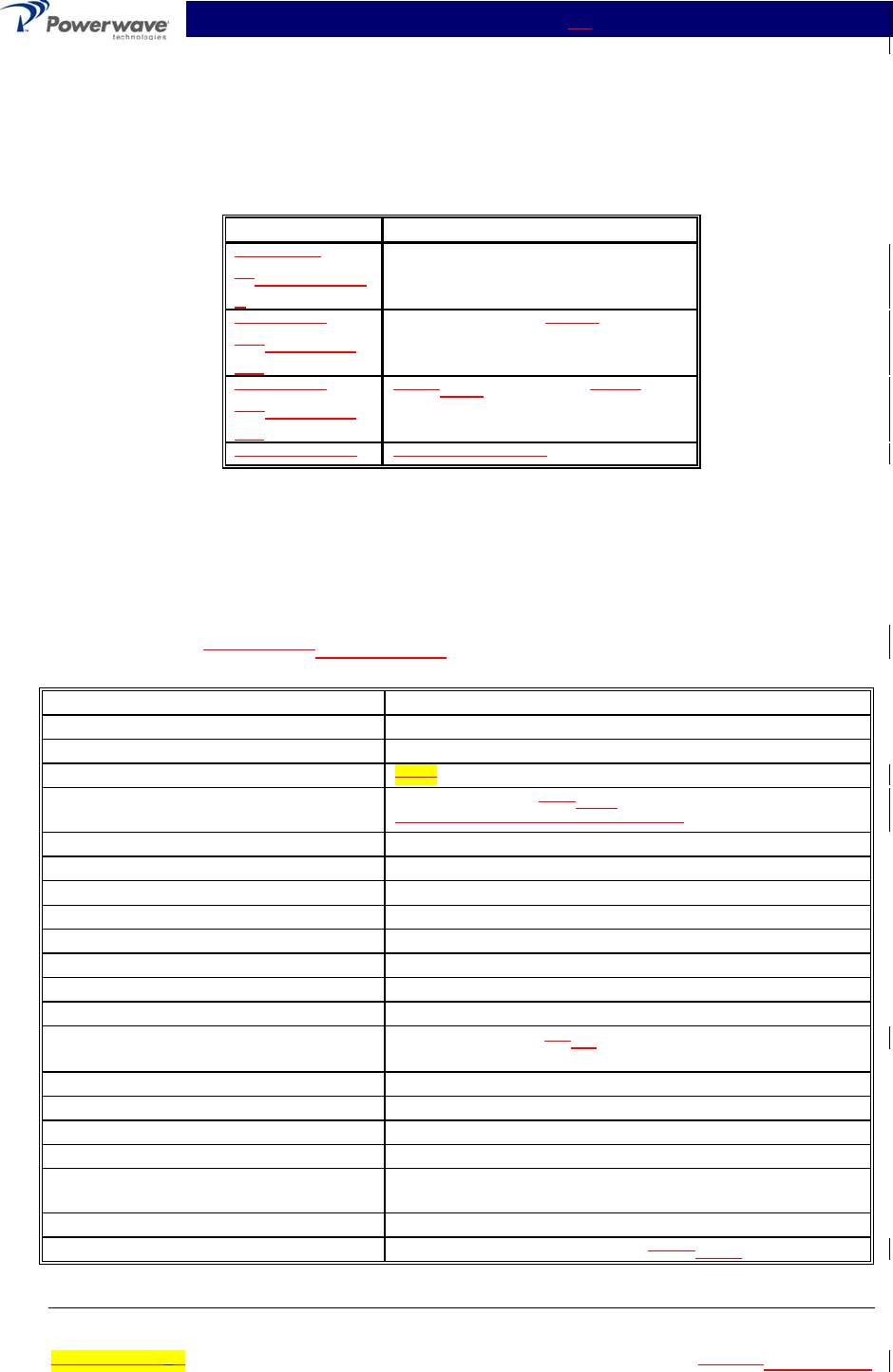
The MCA9129-90MCA9129-90-A (see figure 1-1) is a linear, feed-forward power amplifier that
operates in the 25 MHz frequency band from 869 MHz to 894 MHz. The amplifier can simultane-
ously transmit multiple frequencies, with better than -65 dBc third order intermodulation distortion
(IMD) at 100 watts output, or –60 dBc IMD at 120 watts output. It is designed for use in an ampli-
fier system that is modular in design, and is ideally suited for use in AMPS/TDMA/CDMA base
stations. When used in a subrack employing four MCA9129-90MCA9129-90-A amplifiers, the
system offers up to 360 watts output at
–65dBc IMD performance level (430 watts output at –60dBc IMD). The plug-in Model MCA9129-
90MCA9129-90-A amplifier modules can each provide 120 watts of power and function com-
pletely independently of each other. The amplifier modules are designed for parallel operation to
produce high peak power output and backup redundancy for remote applications. All solid-state,
the system is designed to provide trouble-free operation with minimum maintenance. The sys-
tem's modular construction and unique and highly effective LED-based operational status and
fault indicators help minimize downtime. The turn-on and turn-off sequences of voltages are fully
automatic, as is overload protection and recycling. Inadvertent operator damage from front panel
manipulation is virtually impossible.
Each amplifier module has a status connector that allows the host system to monitor the amplifier
module performance. The front panel of each amplifier module has unit level status/fault indica-
tors and an RF on/off/reset switch. Primary power for the amplifier is +27 Vdc. Cooling for each
plug-in amplifier module is provided by three fans, two mounted on the front and one on the rear
of the module. The fans draw outside air through the front of the module and exhaust hot air out
through the rear of the module.
1-3 Functional and Physical Specifications
Functional and physical specifications for the amplifier are listed in tables 1-2 and 1-3.
1-4 Equipment Changes
Powerwave Technologies, Inc. reserves the right to make minor changes to the equipment, in-
cluding but not necessarily limited to component substitution and circuitry changes. Changes that
impact this manual may subsequently be incorporated in a later revision of this manual. To that
end, we ask that you, our customer, share with us any information acquired in field situations that
would enhance this manual.
MCA9129-90-A Installation & Service Manual
Ó Copyright Powerwave Technologies, Inc., July 2001. All rights reserved
All specifications are subject to change without notice. Contact the factory for complete performance data.
044-05060 Rev. AC1-2 July 2001November 2002
1-5 Ordering Information
Table 1-1 following gives the part numbers and descriptions to be used when ordering either an
entire amplifier or replacement fans.
Table 1-1 Major Amplifier Components
Model Number Description
MCA9129-
90MCA9129-90-
A
100 W 869-894 MHz MCPA Module.
800-01024-
001800-01779-
001
Front fan assembly, large.
800-01025-
001800-01779-
002
Front Rear fan assembly, small
800-00781-002 Rear fan assembly.
NOTE
A quality transmit filter or duplexer must be installed after this amplifier to ensure
FCC Type Acceptance of the amplifier. The filter/duplexer should be rated for at least
500 Watts average power and 5000 Watts instaneous power (minimum) when four
amplifiers per subrack are installed.
Table 1-2 MCA9129-90MCA9129-90-A Multicarrier Cellular Amplifier Functional
Specifications, 100 Watts
Frequency Range 869-894 MHz (25 MHz Bandwidth)
Total Maximum Input Power -12 dBm
Total Output Power 100 W typical (1 Module)
BTUs @ 100 W 3813
Intermodulation Distortion
and In-Band Spurious:
-65 dBc (Min) @ +24 +26 to +28 Vdc @ 100 Watts
(-55 dBc (Min) @ +23 to + 24 Vdc)
RF Gain at 880 MHz 62 dB
Gain Flatness: ± 0.7 dB @ 27 Vdc ±1 Vdc
Gain Variation Over Temperature: ±0.3 dB from 23 to 30 Vdc
Output Protection: Mismatch Protected
Input Port Return Loss: -14 dB (Min)
Harmonics: Better than -50 dBc
Out of Band Spurious: Better than -60 dBc
Duty Cycle: Continuous
DC Input Power: +27 Vdc ± 1 Vdc, 45 36 Amps Max @ 100 Watts
Operational +21 Vdc to 30 Vdc
Operating Temperature: 0 ºC. to +50 ºC.
Storage Temperature: -40 ºC. to +85 ºC.
Operating Humidity: 5 % - 95 % Relative Humidity (Noncondensing)
Storage Humidity: 5 % - 95 % Relative Humidity (Noncondensing)
DC Input, Summary Alarm, and RF
Input / Output Connectors:
21-Pin D-Subminiature Combo Connector plus single-
pin D-Sub connector for additional DC capability.
Weight 45 pounds
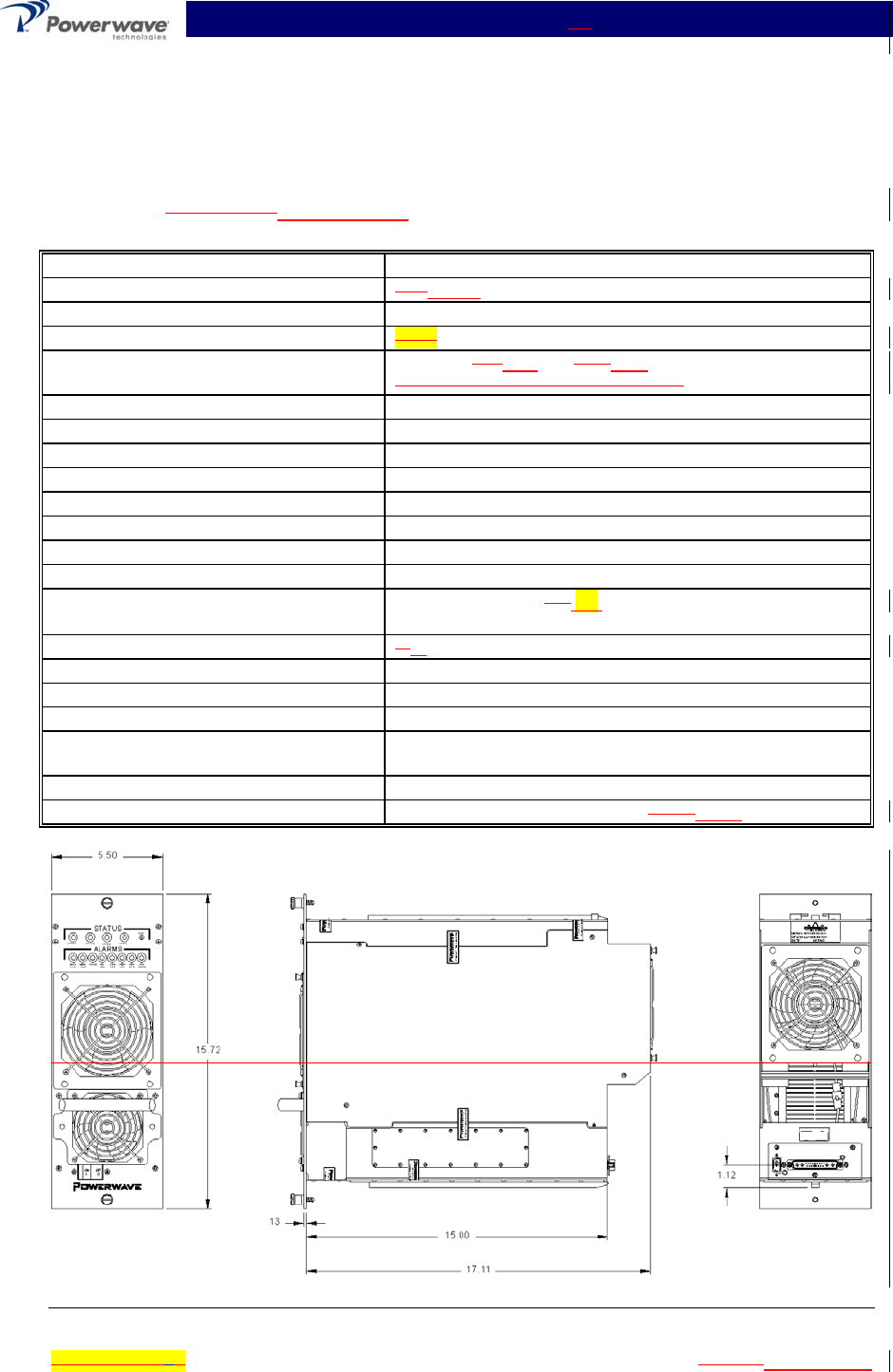
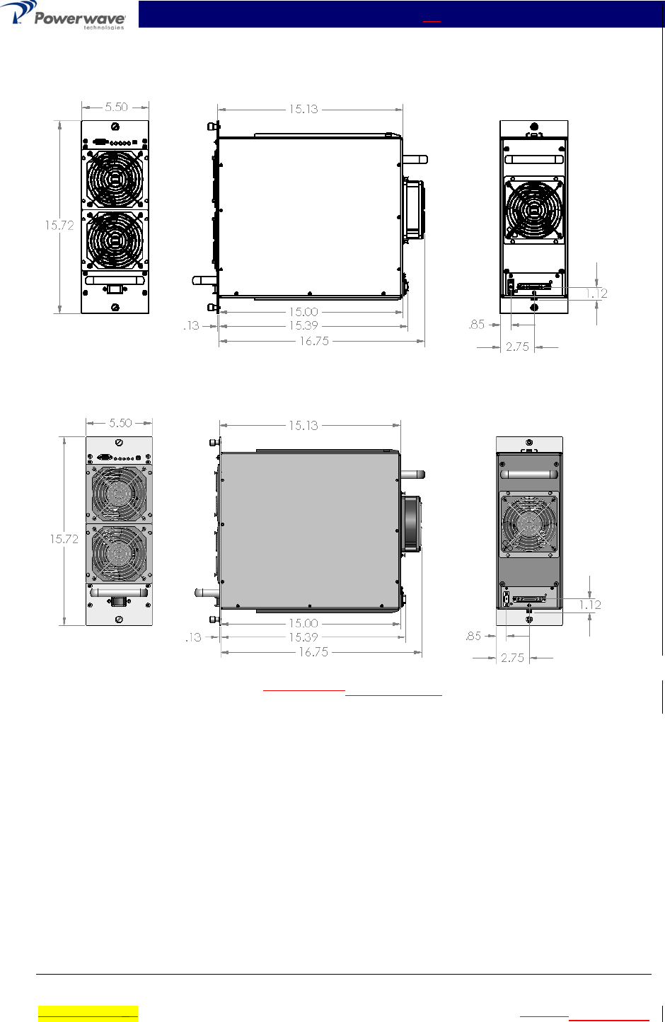
Dimensions: 15.72” (9U) High, 5.50” Wide, 17.1116.75” Deep

MCA9129-90-A Installation & Service Manual
Ó Copyright Powerwave Technologies, Inc., July 2001. All rights reserved
All specifications are subject to change without notice. Contact the factory for complete performance data.
044-05060 Rev. AC1-3 July 2001November 2002
MCA9129-90-A Installation & Service Manual
Ó Copyright Powerwave Technologies, Inc., July 2001. All rights reserved
All specifications are subject to change without notice. Contact the factory for complete performance data.
044-05060 Rev. AC1-4 July 2001November 2002
NOTE
A quality transmit filter or duplexer must be installed after this amplifier to ensure
FCC Type Acceptance of the amplifier. The filter/duplexer should be rated for at least
500 Watts average power and 5000 Watts instaneous power (minimum) when four
amplifiers per subrack are installed.
Table 1-3 MCA9129-90MCA9129-90-A Multicarrier Cellular Amplifier (FCC Tested @ 120
Watts)
Frequency Range 869-894 MHz (25 MHz Bandwidth)
Total Maximum Input Power -11 -11.2dBm
Total Output Power 120 W typical (1 Module)
BTUs @ 120 W 4381
Intermodulation Distortion
and In-Band Spurious:
-60 dBc (MinMax) @ +24 +26 to +28 Vdc @ 120 Watts
(-55 dBc (Min) @ +23 to + 24 Vdc)
RF Gain at 880 MHz 62 dB
Gain Flatness: ± 0.7 dB @ 27 Vdc ±1 Vdc
Gain Variation Over Temperature: ±0.3 dB from 23 to 30 Vdc
Output Protection: Mismatch Protected
Input Port Return Loss: -14 dB (Min)
Harmonics: Better than -50 dBc
Out of Band Spurious: Better than -60 dBc
Duty Cycle: Continuous
DC Input Power: +27 Vdc ± 1 Vdc, 52 40 Amps Max @ 120 Watts
Operational +21 Vdc to 30 Vdc
Operating Temperature: 5 0ºC. to +40 ºC.
Storage Temperature: -40 ºC. to +85 ºC.
Operating Humidity: 5 % - 95 % Relative Humidity (Noncondensing)
Storage Humidity: 5 % - 95 % Relative Humidity (Noncondensing)
DC Input, Summary Alarm, and RF
Input / Output Connectors:
21-Pin D-Subminiature Combo Connector plus single-
pin D-Sub connector for additional DC capability.
Weight 45 pounds
Dimensions: 15.72” (9U) High, 5.50” Wide, 17.1116.75” Deep
MCA9129-90-A Installation & Service Manual
Ó Copyright Powerwave Technologies, Inc., July 2001. All rights reserved
All specifications are subject to change without notice. Contact the factory for complete performance data.
044-05060 Rev. AC1-5 July 2001November 2002
Figure 1-1 MCA9129-90MCA9129-90-A Amplifier

MCA9129-90-A Installation & Service Manual
Ó Copyright Powerwave Technologies, Inc., July 2001. All rights reserved
044-05060 Rev. C 2-1 July 2001November 2002
Section 2 Installation
2-1 Introduction
This section contains unpacking, inspection, and installation instructions / recommendations for
the model MCA9129-90MCA9129-90-A multicarrier cellular amplifier. It is important that the li-
censee perform the following tasks correctly and in good faith:
1. Carefully read all material in this section prior to equipment unpacking or installation.
2. Also, read and review the operating procedures in Section 3 prior to installing the equipment.
3. If applicable, carefully review the Federal Communications Commission (FCC) rules as they
apply to your installation. DON'T TAKE CHANCES WITH YOUR LICENSE.
2-2 Site Survey
Powerwave Technologies recommends that site surveys be performed by qualified individuals or
firms prior to equipment ordering or installation. Performing a detailed site survey will reduce or
eliminate installation and turn-up delays caused by oversights. A general site survey form is pro-
vided in Appendix A. This form is commonly used by Powerwave Field Engineers and may be
used as a guide. Pay particular attention to power plant capacity, air conditioning needs, floor
space, and RF/DC cabling/breaker requirements.
2-3 Electrical Service Recommendations
Powerwave Technologies recommends that proper AC line conditioning and surge suppression
be provided on the primary AC input to the +27 Vdc power source. All electrical service should be
installed in accordance with the National Electrical Code, any applicable state or local codes, and
good engineering practice. Special consideration should be given to lightning protection of all
systems in view of the vulnerability of most transmitter sites to lightning. Lightning arrestors are
recommended in the service entrance. Straight, short ground runs are recommended. The elec-
trical service must be well grounded.
Each amplifier system should have its own circuit breaker (70-amp minimum), so a failure in one
does not shut off the whole installation. Circuit breakers should be thermal type, capable of han-
dling the anticipated inrush current, in a load center with a master switch. See table 2-1.
A typical three-sector site will utilize three MCR4109-1 amplifier subracks, each housing up to four
MCA9129-90MCA9129-90-A amplifiers. The power plant should be able to support the 540 amps
432 amps of current required by this equipment, plus the remaining base station equipment. A
power plant of less than 800 amps is probably not sufficient. Since all the amplifiers are not run-
ning at full capacity at the same time in normal operation, table 2-1 describes the current load for
a 3 sector (70%), 2 sector (80%) and omni (90%) site. Based on this table, an 800 amp power
plant may suffice.
Battery backup or UPS systems should be installed in remote sites or in sites which experience
brownout conditions or generator switchovers. Adding this equipment should eliminate the need
for site visits by technicians after brownouts or power outages. Battery backup systems also pro-
vide excellent DC filtering as a side benefit.
MCA9129-90-A Installation & Service Manual
Ó Copyright Powerwave Technologies, Inc., July 2001. All rights reserved
044-05060 Rev. C 2-2 July 2001November 2002
Table 2-1 Averaged DC Current Load
Amplifier
Power
No. Of
Amplifiers
3 Sector
Averaged Current
2 Sector
Averaged Current
1 Sector
Averaged Current
100 12 378
100 8252 288
100 4126 144 162
100 131.5 36 40.5
2-4 Air Conditioning
Each MCA9129-90MCA9129-90-A amplifier generates 3804 BTUs of heat at full power. A fully
populated MCR4109-1 operating at full power will generate 15,217 BTUs of heat. A full three-
sector site employing three fully populated MCR4109-1 subracks will generate 45,652 BTUs of
heat at full power (360W per subrack). A five-ton air conditioner is needed to cool this Powerwave
equipment. A full three-sector site probably needs at least a five-ton air conditioner to cool all of
the site's equipment, based on heat load averaging as described in table 2-2. Since all the ampli-
fiers are not running at full capacity at the same time in normal operation, table 2-2 describes the
heat load for a 3 sector (70%), 2 sector (80%) and omni (90%) site. Perform a site survey to de-
termine actual air conditioning needs.
Table 2-2 Averaged Heat Loading
Amplifier
Power
No. Of
Amplifiers
3 Sector Averaged
BTU's
2 Sector Averaged
BTU's
1 Sector Aver-
aged BTU's
100 12 31,956.8
100 821,304.5 24,348.0
100 410,652.3 12,174.0 13,695.8
100 12,663.1 3,043.5 3,423.9
2-5 Unpacking and Inspection
This equipment has been operated, tested, and calibrated at the factory. Only in the event of se-
vere shocks or other mistreatment should any substantial readjustment be required. Carefully
unpack each piece of equipment after it has reached the installation site and is approximately in
place. Carefully open the several amplifier system containers and remove the subracks, amplifier
modules, input combiners, and miscellaneous interconnect cables and hardware. Retain all
packing material that can be reassembled in the event that the unit must be returned to the fac-
tory.
CAUTION
Exercise care in handling equipment during inspection to pre-
vent damage caused by rough or careless handling.
Visually inspect the cabinet and all modules for damage that may have occurred during shipment.
Check for evidence of water damage, bent or warped chassis, loose screws or nuts, or extrane-
ous packing material in the connectors or fans. Inspect male connectors on modules and har-
nesses for bent connector pins. If the equipment is damaged, a claim should be filed with the car-
rier once the extent of any damage is assessed. We cannot stress too strongly the importance of
IMMEDIATE careful inspection of the equipment and the subsequent IMMEDIATE filing of the
necessary claims against the carrier if necessary. If possible, inspect the equipment in the pres-
ence of the delivery person. If the equipment is damaged, the carrier is your first area of re-
course. If the equipment is damaged and must be returned to the factory, write or phone for a
return authorization. Powerwave may not accept returns without a return authorization. Claims

MCA9129-90-A Installation & Service Manual
Ó Copyright Powerwave Technologies, Inc., July 2001. All rights reserved
044-05060 Rev. C 2-3 July 2001November 2002
for loss or damage may not be withheld from any payment to Powerwave, nor may any payment
due be withheld pending the outcome thereof. WE CANNOT GUARANTEE THE FREIGHT
CARRIER'S PERFORMANCE.
2-6 Installation Instructions (Refer to figures 1-1 and 2-1)
The MCA9129-90MCA9129-90-A amplifier module is designed for installation in a subrack that
permits access to the rear of the subrack for connection of DC power, RF, and monitor cables.
To install the amplifier proceed as follows:
1. Install the amplifier subrack in the equipment rack and secure in place based the subrack
installation manual instructions.
2. Connect the antenna cable to the output of the subrack.
3. Connect the transceiver output(s) to the input of the subrack. Refer to tables 1-1 and 1-2 for
proper RF input levels.
4. Connect the alarm cable(s) to the subrack.
WARNING
Verify that all circuit breaker switches supplying power to the subrack are in the OFF
position. Turn off external primary DC power before connecting DC power cables.
5. Connect positive primary power and negative primary power to the subrack. Tighten the
subrack power connections.
WARNING
Do not slam amplifiers into the subracks. Forcing the amplifier into the subrack at too
fast a rate may cause the pins on the 21-pin D-sub connector of the amplifier to be-
come recessed or broken. The use of too much force while installing the amplifier
may also cause the splitter / combiner module of the MCR4109-1 to become poorly
aligned resulting in the inoperation of an amplifier installed in one of the two outer
slots.
6. Inspect the 21-pin D-sub connector on the rear of each amplifier before inserting it into the
subrack. Verify that all pins are straight, no pins are recessed, and the alignment shield is
not bent. At the front of the subrack, install the plug-in amplifier modules.
7. After verifying that the front panel power ON / OFF switch is in the OFF position, gently install
the plug-in amplifier modules in the subrack. Tighten top and bottom thumbscrews until they
are finger tight. Use a slotted screwdriver to tighten the thumbscrews an 1/8th to a 1/4 turn
past finger tight.
8. Check your work before applying DC voltage to the system. Make certain all connections are
tight and correct.
9. Measure primary DC input voltage. DC input voltage should be +27 Vdc ±1.0 Vdc. If the DC
input voltage is above or below the limits, call and consult Powerwave before you turn on
your amplifier system.
10. Refer to section 3 for initial turn-on and checkout procedures.
MCA9129-90-A Installation & Service Manual
Ó Copyright Powerwave Technologies, Inc., July 2001. All rights reserved
044-05060 Rev. C 2-4 July 2001November 2002
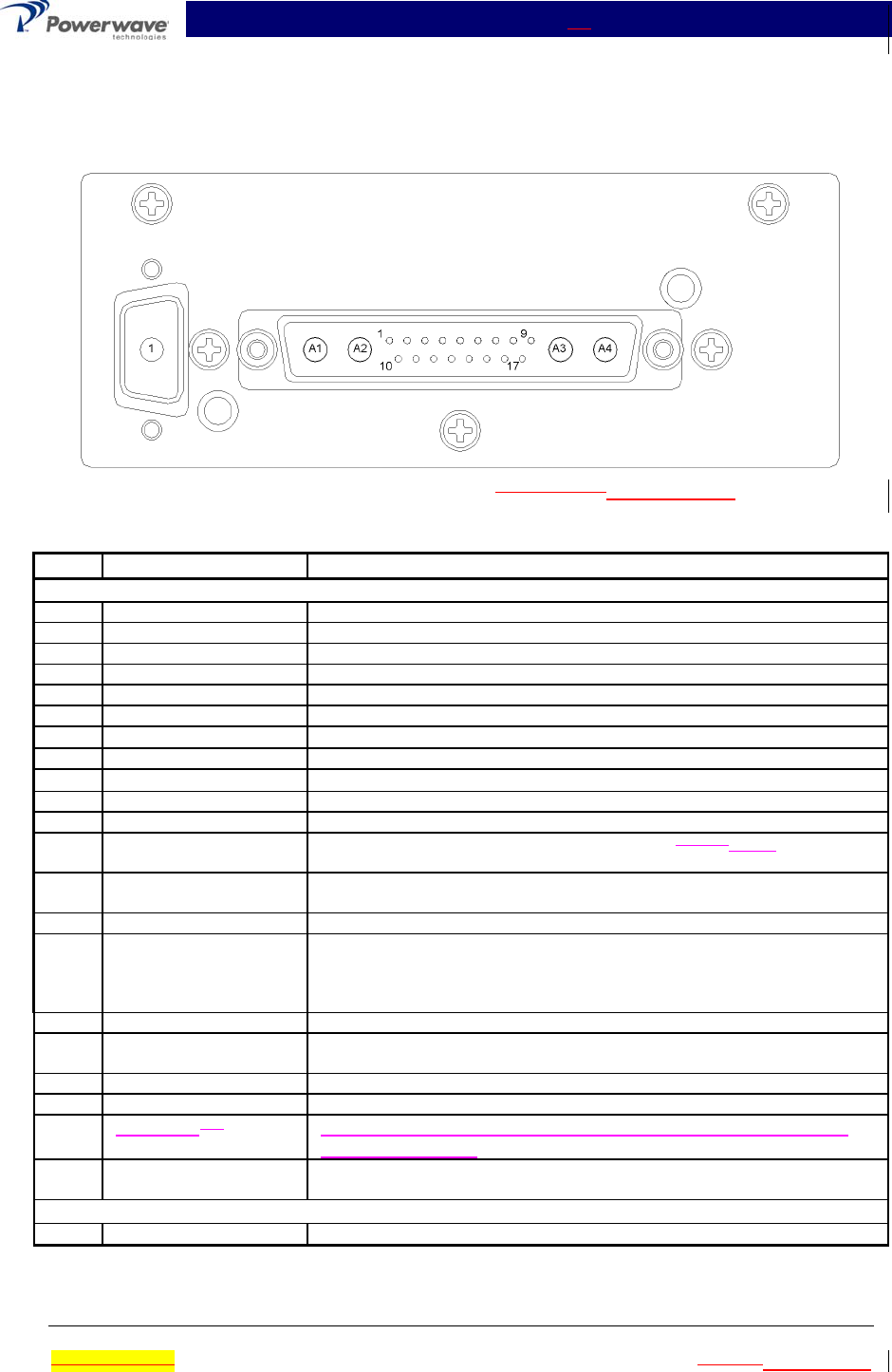
2-7 Multifunction Connector
The status, alarm, control, and power connections on the amplifier connectors are made through
a 21-pin D-Sub male combo connector and supplemental single-pin male D-Sub connector (figure
2-1) and are listed and described in table 2-3.
Figure 2-1 Amplifier Connectors (on Rear of MCA9129-90MCA9129-90-A Module)
Table 2-3 Amplifier Module Status, Alarm, Control, and Power Connections
Pin Function Description
21-Pin D-Sub Male Combo
A1 RF Input Coaxial Contact
A2 Power Input +27 Vdc (Power Contact)
A3 Ground Ground (Power Contact)
A4 RF Output Coaxial Contact
1 Ground Ground
2 RS 485 +RxD Serial Communication Data In
3RS 485 -RxD Serial Communication Data In
4 RS 485 +TxD Serial Communication Data Out
5RS 485 -TxD Serial Communication Data Out
6NA
7NA
8 Fan Fail TTL signal normally low. A high indicates one or bothof the fans have
failed
9 Forward Power Monitor An analog DC signal representing the RF output power of the MCA. The
voltage is 4 volts ± 100 mV at the maximum rated output power.
10 NA
11 Average Power Input An analog DC voltage representing the average detected power of all
the MCAs in a subrack. This voltage is derived from dividing the sum of
all the forward power voltages in a subrack by the number of enabled
MCAs. This voltage is used by the MCA to determine a low power fault.
12 Address A0 Amp Address A0; Ground for high, float for low
13 Summary Fault TTL signal normally low. A high level indicates that the MCA has been
disabled by a recurring alarm fault.
14 Address A1 Amp Address A1; Ground for high, float for low
15 Module Detect Ground potential. Informs the subrack that an MCA is plugged in.
16 Bias InputNA TTL signal normally low for an enabled MCPA. A high level will
disable the MCPA.
17 FP Disable Output TTL signal, low if the front panel switch is in the ON position. A high
level indicates the front panel switch in the OFF position.
Single-Pin D-Sub Male
1 Power Input +27 Vdc (Power Contact)
MCA9129-90-A Installation & Service Manual
Ó Copyright Powerwave Technologies, Inc., July 2001. All rights reserved
044-05060 Rev. C 3-1 July 2001November 2002
Section 3 Operating Instructions
3-1 Introduction
This section contains operating instructions for the Multicarrier Cellular Amplifier.
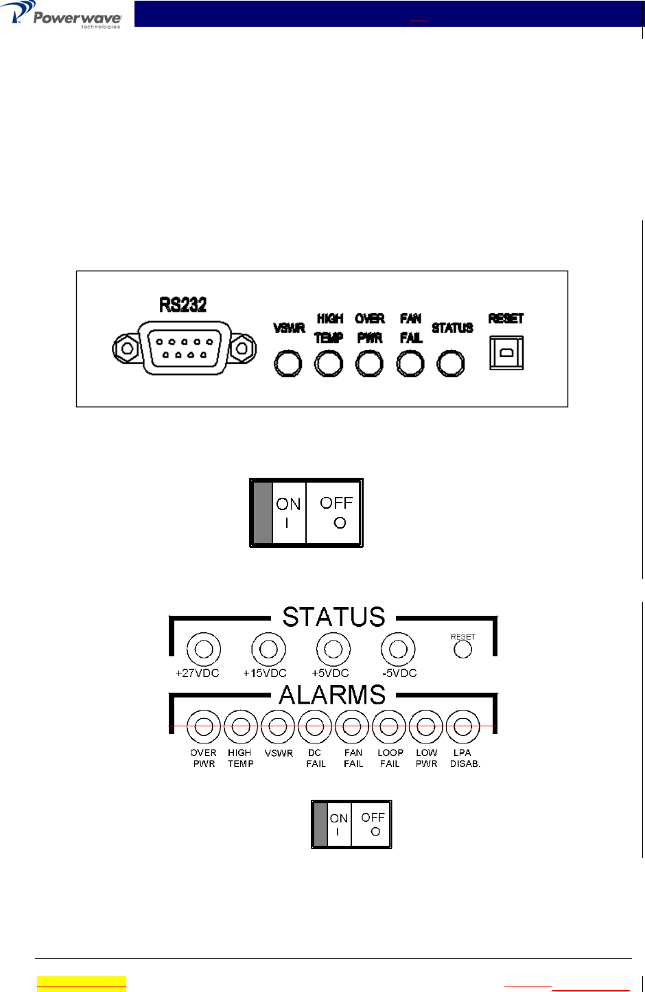
3-2 Location And Function Of Amplifier Module Controls And Indicators
The location and function of the plug-in amplifier module controls and indicators is shown in figure
3-1 and is described in detail in paragraphs 3-3 through 3-3.14.
Figure 3-1. MCA9129-90 Amplifier Module Controls and Indicators
3-3 Controls And Indicators

MCA9129-90-A Installation & Service Manual
Ó Copyright Powerwave Technologies, Inc., July 2001. All rights reserved
044-05060 Rev. C 3-2 July 2001November 2002
3-3.1 27V Indicator (+27VDC)
Green LED. When lit, indicates that the +27Vdc supply is greater than +21Vdc and less than
+30Vdc. The indicator will blink if the voltage is 28Vdc to 30Vdc. If the voltage source drops be-
low +21V a timer is started and the DC fail counter is incremented. After five seconds the voltage
is analyzed, if still faulted the counter is incremented. If the count equals 25 before the timer
reaches 15 minutes, the MCPA will enter fault mode. Fault mode will disable the MCPA. The
+27V indicator will turn off, the DC FAIL and LPA DISAB indicators will illuminate and a summary
fault will occur signaling the shelf that the MCPA is disabled. In fault mode the LED indications
are latched. Toggling the reset switch will enable the MCPA and clear the summary alarm and
latched indicators. If 15 minutes elapse before the counter reaches 25, the counter and timer will
reset to zero. If the DC input voltage exceeds +30 volts, the MCA will be disabled instantane-
ously, as indicated by the illumination of the LPA DISAB indicator. The +27V and DC FAIL indi-
cators will alternatively blink at a 1Hz rate. A timer is started and the DC fail counter is incre-
mented. After five seconds the voltage is measured. If the fault exists the counter is incre-
mented. If the count equals five before the timer reaches 15 minutes, the MCPA will enter fault
mode. The +27V indicator will turn off, the DC FAIL and LPA DISAB indicators will illuminate and
a summary fault will occur signaling the shelf that the MCPA is disabled. Toggling the reset switch
will enable the MCPA and clear the summary alarm and latched indicators. If 15 minutes elapse
before the counter reaches five, the counter and timer will reset to zero.

MCA9129-90-A Installation & Service Manual
Ó Copyright Powerwave Technologies, Inc., July 2001. All rights reserved
044-05060 Rev. C 3-3 July 2001November 2002
3-3.2 +15V Indicator (+15VDC)
Green LED. When lit, indicates that the +15Vdc supply is greater than +14Vdc and less than
+16Vdc. If the voltage source varies out of its operating window, a timer is started and the DC fail
counter is incremented. After five seconds the voltage is analyzed, if still faulted the counter is in-
cremented. If the count equals 25 before the timer reaches 15 minutes, the MCPA will enter fault
mode. Fault mode will disable the MCPA. The +15V indicator will turn off, the DC FAIL and LPA
DISAB indicators will illuminate and a summary fault will occur signaling the shelf that the MCPA
is disabled. In fault mode the LED indications are latched. Toggling the reset switch will enable
the MCPA and clear the summary alarm and latched indicators. If 15 minutes elapse before the
counter reaches 25, the counter and timer will reset to zero.
3-3.3 +5V Indicator (+5VDC)
Green LED. When lit, indicates that the +5Vdc supply is greater than +4.5Vdc and less than
+5.5Vdc. If the voltage source varies out of its operating window, a timer is started and the DC fail
counter is incremented. After five seconds the voltage is analyzed, if still faulted the counter is in-
cremented. If the count equals 25 before the timer reaches 15 minutes, the MCPA will enter fault
mode. Fault mode will disable the MCPA. The +5V indicator will turn off, the DC FAIL and LPA
DISAB indicators will illuminate and a summary fault will occur signaling the shelf that the MCPA
is disabled. In fault mode the LED indications are latched. Toggling the reset switch will enable
the MCPA and clear the summary alarm and latched indicators. If 15 minutes elapse before the
counter reaches 25, the counter and timer will reset to zero.
3-3.4 –5V Indicator (–5VDC)
Green LED. When lit, indicates that the -5Vdc supply is greater than -5.5Vdc and less than -
4.5Vdc. If the voltage source varies out of its operating window, a timer is started and the DC fail
counter is incremented. After five seconds the voltage is analyzed, if still faulted the counter is in-
cremented. If the count equals 25 before the timer reaches 15 minutes, the MCPA will enter fault
mode. Fault mode will disable the MCPA. The -5V indicator will turn off, the DC FAIL and LPA
DISAB indicators will illuminate and a summary fault will occur signaling the shelf that the MCPA
is disabled. In fault mode the LED indications are latched. Toggling the reset switch will enable
the MCPA and clear the summary alarm and latched indicators. If 15 minutes elapse before the
counter reaches 25, the counter and timer will reset to zero.
3-3.5 3-3.1 RESET Switch
Three position switch:
Down Position – Has no effect Disabled.
Center Position - Normal amplifier on position.
RESET (up position) - When toggled to reset position, all the green LED indicators will turn
off and all the red Status LED indicators will illuminate momentarily (LED test); this will also
reset the fault latches. Then a series of fault LEDs will illuminate for 2 seconds to illustrate
configuration type. If the switch is held in the reset position, a microcontroller reset will occur.
This will be verified by the LEDs toggling state again. The switch is spring loaded to return to
the normal ON position when released. If a fault occurs and the MCA is disabled, the alarms
can be cleared and the MCA enabled by this reset position. The functions of the switch are
disabled for five seconds after a power-up condition.
3-3.6 3-3.2 Over Power Indicator (OVER PWR)
Red LED. When blinking,illuminated, indicates the output power from the amplifier has ex-
ceedeedd 120 52dBmwatts. When lit, indicates the output power from the amplifier exceeded

MCA9129-90-A Installation & Service Manual
Ó Copyright Powerwave Technologies, Inc., July 2001. All rights reserved
044-05060 Rev. C 3-4 July 2001November 2002
260 watts. If an over power condition occurs the MCA is immediately disabled. Theand the LPA
DISAB indicator will illuminate and the OVER PWR indicator will blink at a 1Hz rate. A timer is
started and the over power fault counter is incremented. After five seconds the MCA is enabled
and the fault is analyzed. If the fault exists, the MCA is again disabled and the counter is incre-
mented. If the count equals five before the timer reaches 15 minutes, the MCPA will enter fault
mode. Fault mode will disable the MCPA. The OVER PWR and LPA DISAB indicators will illumi-
nate and a summary fault will occur signaling the shelf that the MCPA is disabled. In fault mode
the LED indications are latched. Toggling the reset switch will enable the MCPA and clear the
summary alarm and latched indicators. If 15 minutes elapse before the counter reaches five, the
counter and timer will reset to zero.
3-3.7 3-3.3 High Temperature Indicator (HIGH TEMP)
Red LED. When lit, indicates that the main amplifier heat sinkbase plate temperature has ex-
ceeded 750 °C. If a high temperature condition occurs a timer is started and the high temperature
fault counter is incremented. After five seconds the fault is analyzed. If the fault exists, the
counter is incremented. If the count equals 25 before the timer reaches 15 minutes or if the base
temperature exceeds 85 °C, the MCPA will enter fault mode. Fault mode will disable the MCPA.
The HIGH TEMP and LPA DISAB indicators will illuminate and a summary fault will occur signal-
ing the shelf that the MCPA is disabled. In fault mode the LED indications are latched If the tem-
perature drops below 65 °C, the amplifier will recover to the original enabled state and the alarm
condition will be cleared. Toggling the reset switch will enable the MCPA and clear the summary
alarm and latched indicators. If 15 minutes elapse before the counter reaches 25, the counter
and timer will reset to zero.
3-3.8 3-3.4 VSWR Indicator (VSWR)
Red LED. When lit, indicates that the reflected power detected at the amplifier output exceeds 70
46.5 dBmwatts. If a VSWR condition occurs a timer is started and the VSWR fault counter is in-
cremented. After five seconds the fault is analyzed. If the fault exists, the counter is incremented.
If the count equals 25 before the timer reaches 15 minutes or if the reflected power level exceeds
150W, the MCPA will enter fault mode. Fault mode will disable the MCPA. The VSWR and LPA
DISAB indicators will illuminate and a summary fault will occur signaling the shelf that the MCPA
is disabled. In fault mode the LED indications are latched. Toggling the reset switch will enable
the MCPA and clear the summary alarm and latched indicators. If 15 minutes elapse before the
counter reaches 25, the counter and timer will reset to zero.
3-3.9 DC Fail Indicator (DC FAIL)
Red LED. When lit, indicates that one of the internal DC voltages dropped below or exceeded the
safe threshold level (+21 V<+27 V<+30 V, +14 V<+15 V<+16 V, +4.5 V<+5 V<+5.5 V, or
-5.5 V<-5 V<-4.5 V). If a DC fail condition occurs a timer is started and the DC fail counter is in-
cremented. After five seconds the fault is analyzed. If the fault exists, the counter is incremented.
If the count equals 25 before the timer reaches 15 minutes, the MCPA will enter fault mode. Fault
mode will disable the MCPA. The green indicator representing the invalid voltage will turn-off, the
DC FAIL and LPA DISAB indicators will illuminate and a summary fault will occur signaling the
shelf that the MCPA is disabled. In fault mode the LED indications are latched. Toggling the re-
set switch will enable the MCPA and clear the summary alarm and latched indicators. If 15 min-
utes elapse before the counter reaches 25, the counter and timer will reset to zero. If the DC in-
put voltage exceeds +30 volts, the MCA will be disabled instantaneously, as indicated by the illu-
mination of the LPA DISAB indicator. The +27V and DC FAIL indicators will alternatively blink at a
1Hz rate. A timer is started and the DC fail counter is incremented. After five seconds the voltage
is measured. If the fault exists the counter is incremented. If the count equals five before the
timer reaches 15 minutes, the MCPA will enter fault mode. The +27V indicator will turn off, the
DC FAIL and LPA DISAB indicators will illuminate and a summary fault will occur signaling the
shelf that the MCPA is disabled. Toggling the reset switch will enable the MCPA and clear the

MCA9129-90-A Installation & Service Manual
Ó Copyright Powerwave Technologies, Inc., July 2001. All rights reserved
044-05060 Rev. C 3-5 July 2001November 2002
summary alarm and latched indicators. If 15 minutes elapse before the counter reaches five, the
counter and timer will reset to zero.

MCA9129-90-A Installation & Service Manual
Ó Copyright Powerwave Technologies, Inc., July 2001. All rights reserved
044-05060 Rev. C 3-6 July 2001November 2002
3-3.10 3-3.5 Fan Fail Indicator (FAN FAIL)
Red LED. When lit, indicates that either the upper front or rear one or more fans haves failed.
The lower front fan is not monitored for failure. If one fan fails, the FAN FAIL indicator will light If
the fan speed is below the threshold read at IOC2, 3, 6 or 7, the fan fail alarm LED will be illumi-
nated and a TTL high signal (+5Vdc) will be reported at pin 8 on the back plane connector. Fain
failure will not trigger a summary fault condition.
. If both fans fail, the FAN FAIL indicator will light, a timer is started, and the fan fail counter is in-
cremented. After five seconds the fault is analyzed. If the fault exists, the counter is incremented.
If the count equals 25 before the timer reaches 15 minutes, the MCPA will enter fault mode. Fault
mode will disable the MCPA. The FAN FAIL and LPA DISAB indicators will illuminate and a
summary fault will occur signaling the shelf that the MCPA is disabled. In fault mode the LED in-
dications are latched. Toggling the reset switch will enable the MCPA and clear the summary
alarm and latched indicators. If 15 minutes elapse before the counter reaches 25, the counter
and timer will reset to zero. Indicator is applicable to the large front and rear fans, not to the small
front fan.
Loop Indicator (LOOP FAIL)
Red LED. When lit, indicates that one of the loop control voltages has transitioned above or be-
low safe operating limits. If a loop fail condition occurs a timer is started and the loop fail counter
is incremented. After five seconds the fault is analyzed. If the fault exists, the counter is incre-
mented. If the count equals 25 before the timer reaches 15 minutes, the MCPA will enter fault
mode. Fault mode will disable the MCPA. The LOOP and LPA DISAB indicators will illuminate
and a summary fault will occur signaling the shelf that the MCPA is disabled. In fault mode the
LED indications are latched. Toggling the reset switch will enable the MCPA and clear the sum-
mary alarm and latched indicators. If 15 minutes elapse before the counter reaches 25, the
counter and timer will reset to zero.
3-3.12 Low Power Indicator (LOW PWR)
Red LED. When lit, indicates that the RF power output from the amplifier dropped -2dB (-1,
+0dB) below the average power output of all amplifier modules in the rack. If a low power condi-
tion occurs a timer is started and the low power fault counter is incremented. After five seconds
the fault is analyzed. If the fault exists, the counter is incremented. If the count equals 25 before
the timer reaches 15 minutes, the MCPA will enter fault mode. Fault mode will disable the MCPA.
The LOW PWR and LPA DISAB indicators will illuminate and a summary fault will occur signaling
the shelf that the MCPA is disabled. In fault mode the LED indications are latched. Toggling the
reset switch will enable the MCPA and clear the summary alarm and latched indicators. If 15 min-
utes elapse before the counter reaches 25, the counter and timer will reset to zero.
3-3.13 3-3.6 LPA Disable Indicator (LPA DISAB.) STATUS Indicator
Green/Red LED. When lit, indicates that the MCPA was disabled due to an internal fault or by
positioning the disable switch in the down position. or by the shelf performing the sleep mode
function. If a fault indicator does not accompany the LA DISAB indicator, the sleep mode function
is active.The status LED is green under normal operating conditions.
3.3.7 Power Circuit Breaker (OFF / ON)
Rocker style circuit breaker, which controls DC power to amplifier. The circuit breaker is rated for
100 amps, with amplifier thermal impact considered.

MCA9129-90-A Installation & Service Manual
Ó Copyright Powerwave Technologies, Inc., July 2001. All rights reserved
044-05060 Rev. C 3-7 July 2001November 2002
3-4 Initial Start-Up And Operating Procedures
The only operating controls on each amplifier module are the rocker-style power switch and the
RESET switch.
WARNING
Always turn the amplifier off when disconnecting and reconnecting RF interface ca-
bles. Failure to do so may cause damage to the amplifier and/or personal injury.
To perform the initial start-up, proceed as follows:
1. Verify that all input and output cables are properly connected.
CAUTION
Before applying power, make sure that the input and output of the amplifier are prop-
erly terminated at 50 ohms. Do not operate the amplifier without a load attached. Re-
fer to tables 1-1and 1-2 for input power requirements. Excessive input power may
damage the amplifier
NOTE
The output coaxial cable between the amplifier and the antenna must be 50 ohm co-
axial cable. Use of any other cable, will distort the output.
2. Verify that the amplifier’s front panel power rocker switch is in the OFF position.
3. Turn on the power supply that provides +27 Vdc to the amplifier system. Do not apply an RF
signal to the amplifier system.
4. Set the amplifier’s front panel power rocker switch to the ON position.
5. Visually check the indicators on each amplifier module, and verify that the following indicators
are as follows:
A. LPA DISAB. Indicator (red) should turn off after 2.5 seconds. Status indicator should il-
luminate green immidiately upon startup.
B. The +27VDC, +15VDC, +5VDC and -5VDC indicators (green) on all amplifier modules
should be on. The VSWR, Over Power, High Temp and Fan Fail LEDs should be off.
6. Follow the power setting procedure set forth in the amplifier subrack or system integration
manual. Turn on external exciter/transceiver and apply RF input signals.

MCA9129-90-A Installation & Service Manual
Ó Copyright Powerwave Technologies, Inc., July 2001. All rights reserved
044-05060 Rev. C 4-1 July 2001November 2002
Section 4 Principles of Operation
4-1 Introduction
This section contains a functional description of the Multicarrier Cellular Amplifier.
4-2 RF Input Signal
The maximum input power for all carrier frequencies should not exceed the limits specified in ta-
ble 1-2. For proper amplifier loop balance, the out of band components of the input signals should
not exceed -40 dBc. The input VSWR should be 2:1 maximum (or better).
4-3 RF Output Load
The load impedance should be as good as possible (1.5:1 or better) in the working band for good
power transfer to the load. If the amplifier is operated into a filter, it will maintain its distortion
characteristics outside the signal band even if the VSWR is infinite, provided the reflected power
does not exceed one watt. A parasitic signal of less than one watt incident on the output will not
cause distortion at a higher level than the normal forward distortion (i.e. -65 dBc).
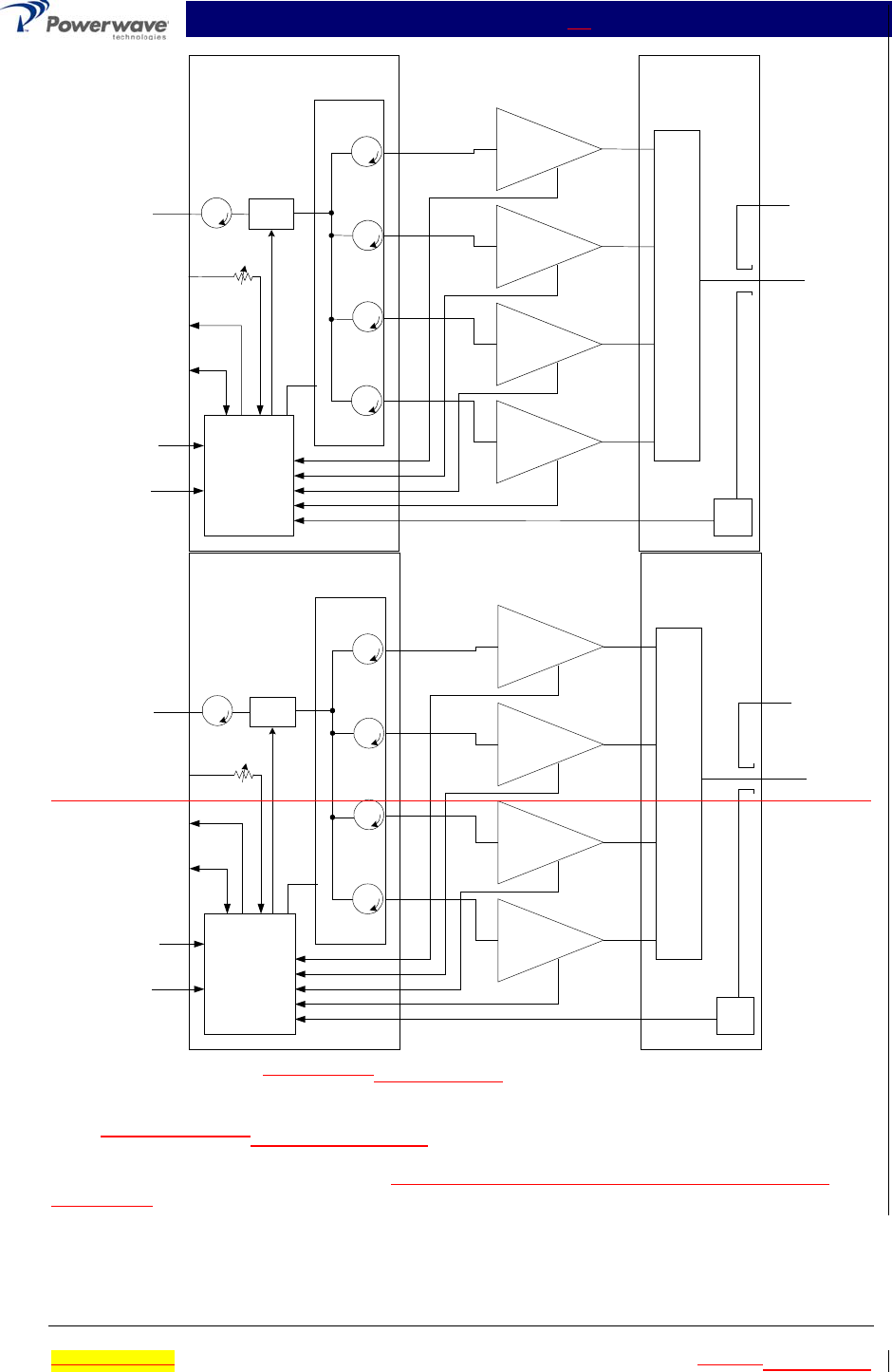
4-4 System Functional Description
The MCA9129-90MCA9129-90-A amplifier is a linear, feed-forward power amplifier that operates
in the 25 MHz frequency band from 869 MHz to 894 MHz. A typical four-module system is shown
in figure 4-1. The power output specification is listed in table 1-2. Each amplifier is a self-
contained plug-in module and is functionally independent of the other amplifier modules. The
amplifier modules are designed for parallel operation to achieve high peak power output, and for
redundancy in unmanned remote locations. Each amplifier in the system can simultaneously
transmit multiple carrier frequencies, at an average total power output of 90 watts (1 amplifier
module in a subrack unit) to 360 watts (4 amplifier modules), with -65 dBc third order intermodula-
tion distortion (IMD). Each amplifier in the system has been FCC tested to simultaneously transmit
multiple carrier frequencies, at an average total power output of 108 watts (1 amplifier module in a
subrack unit) to 430 watts (4 amplifier modules), with -60 dBc third order intermodulation distortion
(IMD). Refer to the MCR4109-1 subrack installation and service manual (044-05061) for com-
plete system level power and IMD specifications.
The output from each amplifier is an amplified composite signal of approximately 100 watts at
–65dBc IMD (120 watts at –60dBc IMD) before combiner losses. All phase and gain corrections
are performed on the signal(s) in the individual amplifier modules. In a four -module system, the
amplifier outputs are fed to a power combiner and combined to form a composite RF output of up
to 360 watts at –65dBc IMD (430 watts at –60dBc IMD). Each amplifier module has an alarm and
display board that monitors the amplifier performance. If a failure or fault occurs in an amplifier
module, it is displayed on the individual amplifier front panel.
MCA9129-90-A Installation & Service Manual
Ó Copyright Powerwave Technologies, Inc., July 2001. All rights reserved
044-05060 Rev. C 4-2 July 2001November 2002
Amplifier Subrack Amplifier
Subrack
MCA9129-90-A
RS-485 Alarm
Interface
VVA C
o
m
b
i
n
e
r
True
RMS
Gain Adjust
Splitter
Micro
Processor
(DC,
RF Relay,
Alarms)
ISO
ISO
ISO
ISO
ISO
Sample
Alarm
Alarm
Alarm
Alarm
Ctrl
4x +27VDC
4x Ground
RF Input
RF Output
Form-C Alarms
MCA9129-90-A
MCA9129-90-A
MCA9129-90-A
Amplifier Subrack Amplifier
Subrack
MCA9129-90
RS-485 Alarm
Interface
VVA C
o
m
b
i
n
e
r
True
RMS
Gain Adjust
Splitter
Micro
Processor
(DC,
RF Relay,
Alarms)
ISO
ISO
ISO
ISO
ISO
Sample
Alarm
Alarm
Alarm
Alarm
Ctrl
4x +27VDC
4x Ground
RF Input
RF Output
Form-C Alarms
MCA9129-90
MCA9129-90
MCA9129-90
Figure 4-1 MCA9129-90MCA9129-90-A Four Module Amplifier System
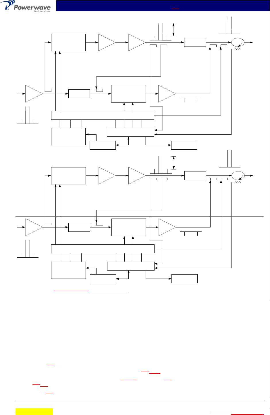
4-5 MCA9129-90MCA9129-90-A Amplifier Module
The amplifier module, figure 4-2, has an average output of 120 watts power (1200 watts peak
power) with intermodulation products suppressed to better than -65 dBc below carrier levels at
100 watts output, -60 dBc at 120 watts output. The amplifier provides an amplified output signal
with constant gain and phase by adding approximately 30 dB of distortion cancellation on the out-
put signal. Constant gain and phase is maintained by continuously comparing active paths with
passive references, and correcting for small variations through the RF feedback controls. All gain

MCA9129-90-A Installation & Service Manual
Ó Copyright Powerwave Technologies, Inc., July 2001. All rights reserved
044-05060 Rev. C 4-3 July 2001November 2002
and phase variations, for example those due to temperature, are reduced to the passive reference
variations. The amplifier module is comprised of:
Preamplifiers
Main amplifier
Error amplifier
Two feed-forward loops with phase-shift and gain controls
DC/DC power regulator
Alarm monitoring, control and display panel
The main amplifier employs class AB amplification for maximum efficiency. The error amplifier
and feed forward loops are employed to correct signal nonlinearities introduced by the class AB
main amplifier. The error amplifier operates in class AB mode. The RF input signals are ampli-
fied by a preamp and coupled to an attenuator and phase shifter in the first feed-forward loop.
The main signal is phase shifted by 180 degrees and amplified in the premain amplifier. The out-
put from the premain amplifier is fed to the class AB main amplifier. The output from the main
amplifier is typically 120 140 watts. The signal is output to several couplers and a delay linefilter.
The signal output from the main amplifier is sampled using a coupler, and the sample signal is
combined with the main input signal and input to the second feed-forward loop. The error signal is
attenuated, phase shifted 180 degrees, then fed to the error amplifier where it is amplified to a
level identical to the sampled output from the main amplifier. The output from the error amplifier
is then coupled back and added to the output from the main amplifier. The control loops continu-
ously make adjustments to cancel out any distortion in the final output signals.
The primary function of the first loop is to provide an error signal for the second loop. The primary
function of the second loop is to amplify the error signal to cancel out spurious products devel-
oped in the main amplifier. The input signal is amplified by a preamplifier and fed to a coupler and
delay line. The signal from the coupler is fed to the attenuator and phase shifter in the 1st loop.
The first loop control section phase shifts the main input signals by 180 degrees and constantly
monitors the output for correct phase and gain.
MCA9129-90-A Installation & Service Manual
Ó Copyright Powerwave Technologies, Inc., July 2001. All rights reserved
044-05060 Rev. C 4-4 July 2001November 2002
Pre
A
mp
Pre
Main
Main
A
mp
Error
A
mp
Delay
Feed Forward Loop control
2nd Loop
Phase & Gain
1st Loop
Phase & Gain Delay
A
larms & Display
+15 +5 -5
Power Supply
-40dB -8.5dB
-40dB
RF Out
RFL
PWR
FWD
PWR
Front Panel
Smart Rack
+27VDC
Pre
Amp
Pre
Main
Main
Amp
Error
Amp
Delay
Feed Forward Loop control
2nd Loop
Phase & Gain
1st Loop
Phase & Gain Delay
Alarms & Display
+15 +5 -5
Power Supply
-30dB -10dB
-40dB
RF Out
RFL
PWR
FWD
PWR
Front Panel
Smart Rack
+27VDC
Figure 4-2 MCA9129-90MCA9129-90-A Power Amplifier Module Functional Block Diagram
The 2nd loop control section obtains a sample of the distortion added to the output signals by the
main amplifiers, phase shifts the signals by 180 degrees, then feeds it to the error amplifier.
There it is amplified to the same power level as the input sample and coupled on to the main out-
put signal. The final output is monitored by the 2nd loop and adjusted to ensure that the signal
distortion and IMD on the final output is canceled out.
4-5.1 Main Amplifier
The input and output of the amplifier employ three-stage, class AB amplifiers which provide ap-
proximately 30 15 dB of gain in the 25 MHz frequency band from 869 MHz to 894 MHz. The am-
plifier operates on +27 Vdc, and a bias voltage of +5 +12 Vdc, and is mounted directly on a heat
sink which is temperature monitored by a digital thermostat IC. If the heat sink temperature ex-
ceeds 92 85 °C, the thermostat opens and a high temperature fault occurs. The alarm logic con-
trols the +5 12 Vdc bias voltage that shuts down the amplifier.

MCA9129-90-A Installation & Service Manual
Ó Copyright Powerwave Technologies, Inc., July 2001. All rights reserved
044-05060 Rev. C 4-5 July 2001November 2002
4-5.2 Error Amplifier
The main function of the error amplifier is to sample and amplify the signal distortion level gener-
ated by the main amplifier, to a level that cancels out the distortion and IMD when the error signal
is coupled onto the main signal at the amplifier output. The error amplifier is a class AB amplifier,
has 50 15 dB of gain. The amplifier operates on +27 Vdc and a bias voltage of +15 +12Vdc and
is mounted directly on a heat sink.

MCA9129-90-A Installation & Service Manual
Ó Copyright Powerwave Technologies, Inc., July 2001. All rights reserved
044-05060 Rev. C 4-6 July 2001November 2002
4-5.3 Amplifier Monitoring
In the main and error amplifier modules, all normal variations are automatically compensated for
by the feedforward loop control. However, when large variations occur beyond the adjustment
range of the loop control, a loop fault will occur. The alarms are displayed in the front panel indi-
cators and output via a 21-pin connector on the rear of the module to the subrack summary board
for subsequent remote monitoring.
4-5.4 Amplifier Module Cooling
Although each amplifier module contains its own heat sink, It is cooled with forced air. Three fans
for are used for forced air cooling and redundancy. The fans are located on the front and rear of
the amplifier module, draw air in through the rear of the amplifier, and exhaust hot air out the front
of the module. The lower front fan is not monitored for failure as are the other two. The fans are
field replaceable (refer to paragraph 5-6.2).
4-6 Power Distribution
Primary DC power for the system is provided by the host system to the subrack. The subrack
supplies each amplifier module with +27 Vdc directly and via the RF power splitter/combiner. The
amplifier module has linear and switching regulators that generates required DC voltages such as
a DC/DC converter that converts the +27 Vdc to +15 Vdc, +5 Vdc, +9V and -5 Vdc from +27Vdc.
4-7 Intermodulation
The MCA9129-90MCA9129-90-A amplifier is designed to deliver a 120-watt composite average
analog power, multicarrier signal, occupying a bandwidth less than or equal to 25 MHz, in the
bandwidth from 869-894 MHz. The maximum average power for linear operation, and thus the
amplifier efficiency, will depend on the type of signal amplified.
4-7.1 Two-Tone Intermodulation
When measured with two equal CW tones spaced anywhere from 30 kHz to 25 MHz apart, and at
any power level up to the peak power, the third order intermodulation products will be below
-65 dBc at 100 watts output, below –60 dBc at 120 watts output.
4-7.2 Multitone Intermodulation
Adding more tones to the signal will lower individual intermodulation products. If the frequencies
are not equally spaced, the level of intermodulation products gets very low. When the frequencies
are equally spaced, those products fall on top of each other on the same frequency grid. The av-
erage power of all intermodulation beats falling on the same frequency is called the composite in-
termodulation; it is -65 dBc @ 100 W output, -60 dBc @ 120 W output, or better, with a maximum
of one MHz channel spacing.
MCA9129-90MCA9129-90-A Installation & Service Manual
Ó Copyright Powerwave Technologies, Inc., July 2001. All rights reserved
044-05060 Rev. C 5-1 July 2001November 2002
Section 5 Maintenance
5-1 Introduction
This section contains periodic maintenance and performance test procedures for the Multicarrier
Cellular Amplifier. It also contains a list of test equipment required to perform the identified tasks.
NOTE
Check your sales order and equipment warranty before attempting to service or repair
the unit. Do not break the seals on equipment under warranty or the warranty will be
null and void. Do not return equipment for warranty or repair service until proper
shipping instructions are received from the factory.
5-2 Periodic Maintenance
Periodic maintenance requirements are listed in table 5-1. Table 5-1 also lists the intervals at
which the tasks should be performed.
WARNING
Wear proper eye protection to avoid eye injury when using compressed air.
Table 5-1 Periodic Maintenance
Task Interval Action
Cleaning
Air Vents 30 Days Inspect and clean per paragraph 5-4
Inspection
Cables and
Connectors
12
Months
Inspect signal and power cables for frayed insulation. Check
RF connectors to be sure that they are tight.
Performance Tests 12
Months
Perform annual tests in accordance with individual manuals
for amplifiers.
5-3 Test Equipment Required For Test
Test equipment required to test the amplifier system is listed in Table 5-2. Equivalent test equip-
ment may be substituted for any item, keeping in mind that a thermistor type power meter is re-
quired.
NOTE
All RF test equipment must be calibrated to 0.05 dB resolution. Any deviation from
the nominal attenuation must be accounted for and factored into all output readings.
MCA9129-90MCA9129-90-A Installation & Service Manual
Ó Copyright Powerwave Technologies, Inc., July 2001. All rights reserved
044-05060 Rev. C 5-2 July 2001November 2002
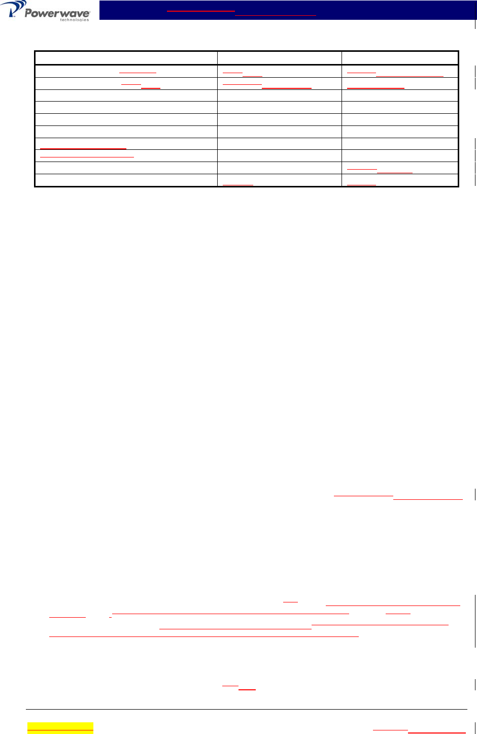
Table 5-2 Test Equipment Required
Nomenclature Manufacturer Model
Signal Generator (4 each) H.P.RDL 8656BIMD-801D-03A
20 dB Attenuator, 250 500 Watt Tenuline Weinschel WA53-20-34
20 dB Attenuator, 20 Watt (2 each) Tenuline
Spectrum Analyzer H.P. 8560E
Coax Directional Coupler H.P. 778D
Power Meter / Sensor H.P. 437B / 8481A
Variable Attenuator
Four Tone Combiner
Network Analyzer H.P. 8753C8753ES
Current Probe Agilent 1146A
5-4 Cleaning Air Inlets/Outlets
The air inlets and outlets should be cleaned every 30 days. If the equipment is operated in a se-
vere dust environment, they should be cleaned more often as necessary. Turn off DC power
source before cleaning fans. If dust and dirt are allowed to accumulate, the cooling efficiency may
be diminished. Using either compressed air or a brush with soft bristles, loosen and remove ac-
cumulated dust and dirt from the air inlet panels.
5-5 Performance Test
Performance testing should be conducted every 12 months to ensure that the amplifier system
meets the operational specifications listed in table 5-3. Also verify system performance after any
amplifier module is replaced in the field. The test equipment required to perform the testing is
listed in table 5-2, and the test setup is shown in figure 5-1.
NOTE
The frequencies used in this test are typical for an amplifier with a 25-MHz band from
869 MHz to 894 MHz. Select evenly spaced F1, F2, F3, and F4 frequencies, that
cover the instantaneous bandwidth of your system.
5-5.1 Amplifier Performance Test
This test is applicable to a subrack equipped with one to four plug-in MCA9129-90MCA9129-90-A
amplifier modules. Perform the tests applicable to your system. To perform the test, proceed as
follows:
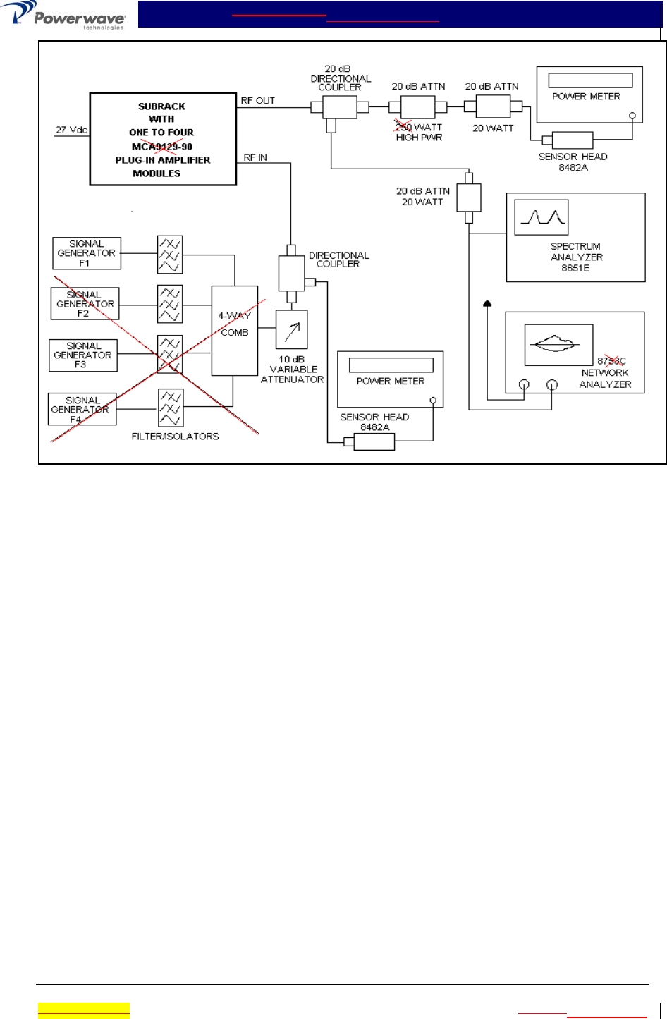
1. Connect test equipment to the subrack as shown in figure 5-1.
NOTE
Do not apply any RF signals at this time.
2. Turn on all four signal generators and set frequency F1 to 880, 881, 882, 883, 884, 885, 886
and 887 MHz., F2 to 881 MHz, F3 to 882 MHz, and F4 to 883 MHz. Adjust each signal gen-
erator output so that the composite power equals –12dBm.sum power output from all four
signal generators equals -4 dBm at the output of the 4-way combiner.
5-5.1.1 Single Amplifier IMD Test
3. Adjust attenuator for an input signal at –l2 -12dBm. Reset channel 1 amplifier with the front
panel ON/OFF/RESET switch, and set switch to ON. Set amplifiers 2, 3, and 4 to OFF. Ad-

MCA9129-90MCA9129-90-A Installation & Service Manual
Ó Copyright Powerwave Technologies, Inc., July 2001. All rights reserved
044-05060 Rev. C 5-3 July 2001November 2002
just variable attenuator to set amplifier power output on power meter to 90 watts. Measure
IMD on spectrum analyzer. IMD should be -65 dBc max. Record test data in table 5-3.
Switch tested amplifier to OFF.
4. Repeat step 3 for amplifiers 2, 3, and 4, as applicable, for each plug-in amplifier module.
5-5.1.2 Two Amplifier IMD Test
5. Reset and turn on channel 1 and 2 amplifier modules, and turn off channel 3 and 4 amplifi-
ers. Adjust the variable attenuator to set power output on power meter to 180 watts. Meas-
ure IMD on spectrum analyzer. IMD should be -65 dBc maximum. Record test data in table
5-3.
6. Reset and turn on channel 1 and 3 amplifiers, and turn off channel 2. Adjust the variable at-
tenuator to set power output on power meter to 180 watts. Measure IMD on spectrum ana-
lyzer. IMD should be -65 dBc maximum. Record test data in table 5-3.
7. Reset and turn on channel 1 and 4 amplifiers and turn off channel 3. Adjust the variable at-
tenuator to set power output on power meter to 180 watts. Measure IMD on spectrum ana-
lyzer. IMD should be -65 dBc maximum. Record test data in table 5-3.
8. Reset and turn on channel 2 and 3 amplifiers, and turn off channel 1. Adjust the variable at-
tenuator to set power output on power meter to 180 watts. Measure IMD on spectrum ana-
lyzer. IMD should be -65 dBc maximum. Record test data in table 5-3.
9. Reset and turn on channel 2 and 4 amplifiers, and turn off channel 3. Adjust the variable at-
tenuator to set power output on power meter to 180 watts. Measure IMD on spectrum ana-
lyzer. IMD should be -65 dBc maximum. Record test data in table 5-3.
10. Reset and turn on channel 3 and 4 amplifiers, and turn off channel 2. Adjust the variable at-
tenuator to set power output on power meter to 180 watts. Measure IMD on spectrum ana-
lyzer. IMD should be -65 dBc maximum. Record test data in table 5-3.
5-5.1.3 Three Amplifier IMD Test
11. Reset and turn on channel 1, 2 and 3 amplifiers, and turn off channel 4. Adjust the variable
attenuator to set power output on power meter to 270 watts. Measure IMD on spectrum
analyzer. IMD should be -65 dBc maximum. Record test data in table 5-3.
12. Reset and turn on channel 1, 2 and 4 amplifiers, and turn off channel 3. Adjust the variable
attenuator to set power output on power meter to 270 watts. . Measure IMD on spectrum
analyzer. IMD should be -65 dBc maximum. Record test data in table 5-3.
13. Reset and turn on channel 1, 3 and 4 amplifiers, and turn off channel 2. Adjust the variable
attenuator to set power output on power meter to 270 watts. Measure IMD on spectrum
analyzer. IMD should be -65 dBc maximum. Record test data in table 5-3.
14. Reset and turn on channel 2, 3 and 4 amplifiers, and turn off channel 1. Adjust the variable
attenuator to set power output on power meter to 270 watts. Measure IMD on spectrum
analyzer. IMD should be -65 dBc maximum. Record test data in table 5-3.
5-5.1.4 Four Amplifier IMD And Current Test
15. Reset and turn on channel 1, 2, 3, and 4 amplifiers. Adjust the variable attenuator to set
power output on power meter to 360 watts. Measure IMD on spectrum analyzer. IMD should
be -65 dBc maximum. Record test data in table 5-3.
16. With the power amplifier set at 360 watts power output, use the current probe (magnetic field
type) and measure the dc current flow from the +27 Vdc power source. Current should be
180 144 amps maximum. Record test data in table 5-3.

MCA9129-90MCA9129-90-A Installation & Service Manual
Ó Copyright Powerwave Technologies, Inc., July 2001. All rights reserved
044-05060 Rev. C 5-4 July 2001November 2002
5-5.1.5 Harmonics Test
17. With the power amplifier set at 360 watts power output, use the spectrum analyzer and check
the frequency band from 869 MHz to 894 MHz for harmonics. Harmonics should be -50 dBc
maximum. Record test data in table 5-3.
5-5.1.6 Spurious Test
18. With the power amplifier set at 360 watts power output, use the spectrum analyzer and check
the frequency band from 869 MHz to 894 MHz for spurious signals. Spurious signals should
be -65 dBc maximum. Record test data in table 5-3.
5-5.1.7 Gain Test
19. Disconnect spectrum analyzer from test setup, and connect the network analyzer.
20. Set network analyzer as follows:
A. Power output to -–4 -12 dBm.
B. Frequency start to 869 MHz.
C. Frequency stop to 894 MHz.
D. Normalize the network analyzer for gain and return loss.
21. Reset and turn on the channel 1 amplifier, turn off channel 2, 3 and 4 amplifiers. Check the
gain across the band from 869 MHz to 894 MHz. Gain should be as specified in table 1-2 ±1
dB. Record test data in table 5-3.
22. Turn off the channel 1 amplifier and reset and turn on the channel 2 amplifier. Check the
gain across the band from 869 MHz to 894 MHz. Gain should be as specified in table 1-2 ±1
dB. Record test data in table 5-3.
23. Repeat steps 21 and 22 and individually check and record the gain of each amplifier module
in the system. Record test data in table 5-3.
24. Refer to table 5-3. Collectively reset and turn on the amplifier modules in groups of two three
and four, as shown in table 5-3, and check the gain of each group. The minimum/maximum
gain of each group of amplifiers should be within the limits shown in table 5-3. Record test
data in table 5-3.
5-5.1.8 Input Return Loss Test
25. Reset and turn on all amplifier modules in the main frame. Read and record the S11 return
loss measurement on network analyzer. Record test data in table 5-3.
MCA9129-90MCA9129-90-A Installation & Service Manual
Ó Copyright Powerwave Technologies, Inc., July 2001. All rights reserved
044-05060 Rev. C 5-5 July 2001November 2002
Figure 5-1 Amplifier System Test Setup Diagram
MCA9129-90MCA9129-90-A Installation & Service Manual
Ó Copyright Powerwave Technologies, Inc., July 2001. All rights reserved
044-05060 Rev. C 5-6 July 2001November 2002
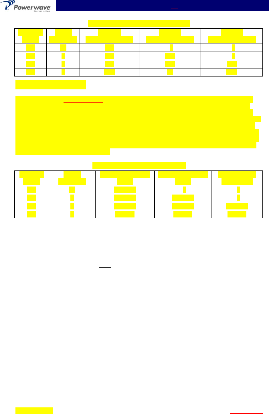
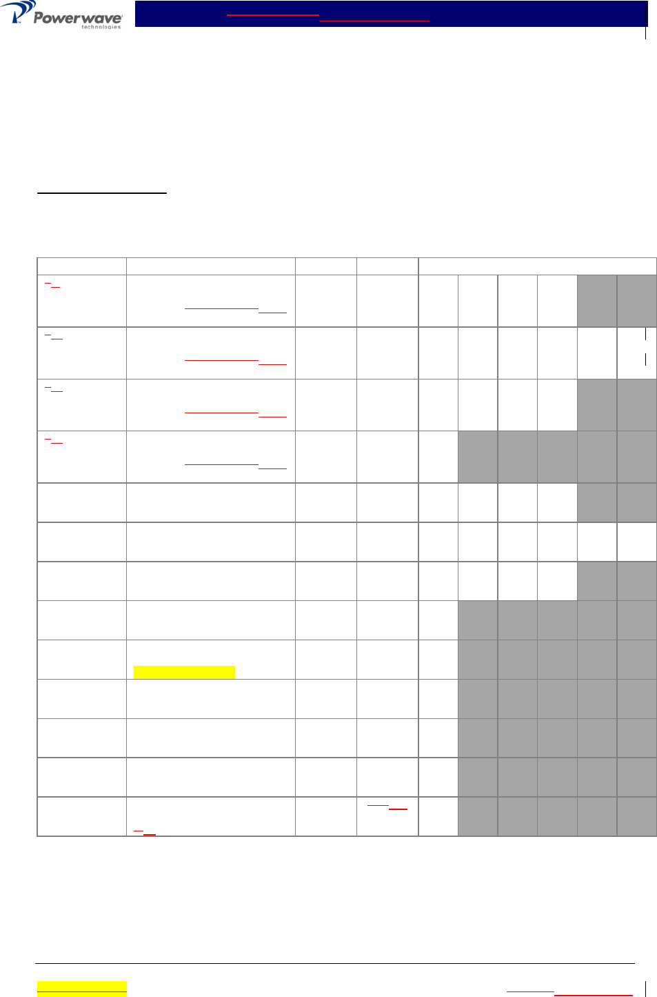
Table 5-3 Multicarrier Cellular Amplifier Test Data Sheet
DATE _________________________________
MODULE #1 S/N ________________________ MODULE #2 S/N ________________________
MODULE #3 S/N ________________________ MODULE #4 S/N ________________________
TEST CONDITIONS:
Load and Source Impedance: 50 Ohms
VSWR: < 1.2:1
Supply Voltage: +27 Vdc ±0.1 Vdc
TEST SPECIFICATION MIN MAX DATA
4 8-TONE IMD
One Module
Vcc = 27 Vdc
PO = 90 W
Freq.: 880, 881, 882, 883 - 887
MHz
-65 dBc1234
4 8 -TONE
IMD
Two Modules
Vcc = 27 Vdc
PO = 180 W
Freq.: 880, 881, 882, 883 - 887
MHz
-65 dBc 1,2 1,3 1,4 2,3 2,4 3,4
4 8 -TONE
IMD
Three Modules
Vcc = 27 Vdc
PO = 270 W
Freq.: 880, 881, 882, 883 - 887
MHz
-65 dBc 1,2,3 1,2,4 1,3,4 2,3,4
4 8 -TONE
IMD
Four Modules
Vcc = 27 Vdc
PO = 360 W
Freq.: 880, 881, 882, 883 - 887
MHz
-65 dBc All
RF Gain
One Module
Vcc = 27 Vdc
PO = 90 W
Freq. = 880 MHz
Table 1-2
-1 dB
Table 1-2
+1 dB
1234
RF Gain
Two Modules
Vcc = 27 Vdc
PO = 180 W
Freq. = 880 MHz
Table 1-2
-1 dB
Table 1-2
+1 dB
1,2 1,3 1,4 2,3 2,4 3,4
RF Gain
Three Modules
Vcc = 27 Vdc
PO = 270 W
Freq. = 880 MHz
Table 1-2
-1 dB
Table 1-2
+1 dB
1,2,3 1,2,4 1,3,4 2,3,4
RF Gain
Four Modules
Vcc = 27 Vdc
PO = 360 W
Freq. = 880 MHz
Table 1-2
-1 dB
Table 1-2
+1 dB
All
Harmonics Vcc = 27 Vdc
PO = 360 W
869 - 894 MHz Band
-50 dBc All
Spurious Vcc = 27 Vdc
PO =360 W
869 - 894 MHz Band
-65 dBc All
Gain Flatness Vcc = 27 Vdc
PO =360 W
869 - 894 MHz Band
±0.7 dB All
Input Return
Loss
Vcc = 27 Vdc
PO = 360 W
869-894 MHz Band
-18 dB All
DC Power Vcc = 27 Vdc
PO = 360 W
4 8 Tones
180 144
Amps
All
PASS ___________________________________ FAIL ___________________________________
Tested by ________________________________

MCA9129-90MCA9129-90-A Installation & Service Manual
Ó Copyright Powerwave Technologies, Inc., July 2001. All rights reserved
044-05060 Rev. C 5-7 July 2001November 2002
5-6 Field Replaceable Parts And Modules
The following parts and modules can be replaced in the field on site by a qualified technician with
experience maintaining RF power amplifiers and similar equipment:
1. MCA9129-90MCA9129-90-A Power Amplifier Modules
2. Cooling Fans
5-6.1 MCA9129-90MCA9129-90-A Power Amplifier Module
To replace a power amplifier module, proceed as follows:
1. Set ON/OFF/RESET switch on the front panel of the amplifier module to OFF.
2. Loosen two screws that secure amplifier module to subrack.
CAUTION
When removing the amplifier from the subrack, it is very important to support the am-
plifier such that the rear of the module does not suddenly drop when the guide rail
disengages from the track. A drop such as this could damage the rear multipin con-
nector.
3. With steady even pressure, use handle on front of amplifier to pull module out of subrack.
5-6.2 Cooling Fans
To replace a cooling fan, proceed as follows:
1. Remove amplifier module from subrack; see paragraph 5-6.1 preceding.
2. Pull out snap fasteners that secure fan to amplifier module. Disconnect fan power connector
from amplifier module.
3. Install replacement in reverse order of steps 1 and 2 above.

MCA9129-90MCA9129-90-A Installation & Service Manual
Ó Copyright Powerwave Technologies, Inc., July 2001. All rights reserved
044-05060 Rev. C 6-1 July 2001November 2002
Section 6 Troubleshooting
6-1 Introduction
This section contains a list of problems and a few suggested actions that may correct the prob-
lem. If the suggested corrective action does not eliminate the problem, please contact your Pow-
erwave field representative or the factory for further instructions.
NOTE
Check your sales order and equipment warranty before attempting to service or repair
the unit. Do not break the seals on equipment under warranty or the warranty will be
null and void. Do not return equipment for warranty or repair service until proper
shipping instructions are received from the factory.
6-2 Troubleshooting
The ON/RESET switch can clear many alarm faults. It is located on the front panel of the faulted
amplifier module. An attempt to reset the fault should be your first course of action. 24 Hour tech-
nical support service is available at our main phone number 888-797-9283 or 714-466-1000; se-
lect the "System Operator Technical Support" option to receive assistance from Powerwave's Ap-
plications Support Group.
The following are general guidelines established to aid Field Engineers or Cell Site Technicians in
the proper method of Powerwave equipment fault resolution by fault mode.
6-2.1 DC Voltage Indicators Not Status Lamp not Illuminated
1. Check the front panel ON/OFF switch.
2. Check the power plant circuit breaker.
3. Check for +27 + 1.0 VDC at the amplifier subrack input.
A. If the voltage is low, verify that all DC connections between the power plant and the am-
plifier subrack are tight.
B. If the voltage is correct,
1. Remove the amplifier from the subrack slot and move the amplifier to another am-
plifier subrack slot.
2. Check the voltage on the power pins of the mating amplifier and amplifier subrack
connector.
3. Verify that the amplifier DC connections are not damaged.
4. Return the amplifier to the factory for repair.
6-2.2 OVER PWR Illuminated or Blinking
1. If all the amplifiers in a given amplifier subrack are in Over Pwr and the LPA DisableStatus
LED is illuminate, then the input RF power level is too high and the amplifiers have been dis-
abled. RF power may be incorrectly set during equipment commissioning. This may be due
to a faulty jumper cable. Verify the amplifier subrack output cables, transmit filter, and direc-
tional coupler are in proper working order. The loss between the amplifier subrack and the
hatch plate is typically less than 2.0 dB.

MCA9129-90MCA9129-90-A Installation & Service Manual
Ó Copyright Powerwave Technologies, Inc., July 2001. All rights reserved
044-05060 Rev. C 6-2 July 2001November 2002
2. If all the amplifiers in a given amplifier subrack are in Over Pwr and the LPA DisableStatus
LED is not illuminated, then the input RF power level is too high. The amplifier subrack is at-
tempting to maintain a safe power output level (smart subracks with True RMS power de-
tectors and voltage variable attenuators only). This may be validated by checking the APC
LED on the subrack for a blinking state. RF power may be incorrectly set during equipment
commissioning. This may be due to a faulty jumper cable. Verify the amplifier subrack output
cables, transmit filter, and directional coupler are in proper working order. The loss between
the amplifier subrack and the hatch plate is typically less than 2.0 dB.
3. If only one or two amplifiers in a given amplifier subrack are in Over Pwr and the LPA Dis-
ableStatus LED is blinkingis illuminated after disabling or removing an amplifier, then the
amplifier subrack is probably in Sleep ModeConstant Gain Mode.(smart subracks with True
RMS power detectors and voltage variable attenuators only).
A. The input power level must be adjusted to compensate for the loss of any module when
in constant gain mode. Pressing the On/Off/Reset switch momentarily in the Up position
or cycling DC power on the amplifier should bring the amplifier back on-line.
B. Sleep ModeConstant gain firmware may be disabled in the field with a PC interface and
software available from Powerwave.
4. Move the amplifier to another slot in a different subrack, if available. Mark the amplifier with a
sticker or place a tie wrap on the handle to identify the amplifier. Monitor for future failure.
A. If the same amplifier fails again, return the amplifier to the factory for repair.
B. If the replacement amplifier in the original subrack fails, replace the amplifier subrack.
6-2.3 HIGH TEMP Illuminated
1. If an amplifier is in HIGH TEMP and the LPA DisableStatus LED is illuminate, then the ampli-
fier heat sinkmain amp base plate temperature is too high. This may be due to:
A. High ambient temperature.
B. Fan failure.
C. Insufficient air-volume capacity. Most of Powerwave’s amplifiers require a certain
amount of free-space to allow proper airflow.
2. Correct the heat problem, then reset the amplifier by momentarily pressing the Reset button
on the amplifier front panel up.
6-2.4 VSWR Illuminated
1. If all the amplifiers in a given amplifier subrack are in VSWR and the LPA DisableStatus LED
is illuminate, then the output RF reflected power level is too high and the amplifiers have
been disabled. This may be due to a faulty jumper cable or transmit filter. Verify the amplifier
subrack output cables, transmit filter, and directional coupler are in proper working order. The
loss between the amplifier subrack and the hatch plate is typically less than 2.0 dB. This fault
normally occurs during site or just following site power setting and normally takes about 10 to
15 minutes to reveal itself. This fault may not occur at low power levels (i.e. when just one or
two channels are up).
2. If one amplifier in a given amplifier subrack is in VSWR and the LPA Disable LED is illumi-
nated, then the output RF reflected power level is too high for that amplifier. This may be due
to
A. A damaged or recessed amplifier RF output connector. Return the amplifier to the fac-
tory for repair.
Mishandling of the amplifier normally causes recessed pins. Before installing an ampli-
fier, look at the D-sub connector to ensure none of the pins are recessed, bent or that

MCA9129-90MCA9129-90-A Installation & Service Manual
Ó Copyright Powerwave Technologies, Inc., July 2001. All rights reserved
044-05060 Rev. C 6-3 July 2001November 2002
the outer connector shield is not damaged. When installing the amplifier, do not force
the amplifier into the slot. Gentle even pressure is all that is needed to properly seat the
amplifier.
B. Improper seating of the amplifier.
1. Ensure the amplifier thumbscrews are properly tightened.
2. Try seating the amplifier in another subrack slot.
3. Try seating the amplifier in a subrack in another sector.
6-2.5 DC FAIL Illuminated
If an amplifier is in DC FAIL and the LPA Disable LED is illuminate, then one of the four amplifier
DC voltages is either out of tolerance or not present. Return the amplifier to the factory for repair.
6-2.6 6-2.5 FAN FAIL Illuminated
If an amplifier is in FAN FAIL, then the one or more of the amplifier’s cooling fans has failed. Re-
place the fan.
Model MCA9129-90MCA9129-90-A Amplifiers
A single A fan failure does not cause the amplifier to shut down.
Two failed large fans cause the amplifier to shut down. These amplifiers have a small fan on
the front lower panel. The smaller front fan’s performance is not monitored.
6-2.7 6-2.6 LOOP FAIL Illuminated
Loop Fail is always accompanied by LPA Disable LED illuminated. This may be due to
1. Inability of the amplifier to maintain a 180° phase shift between the first and second loops.
2. A damaged error amplifier. This can be caused by
A. Out of band spurious or intermods being applied at too high of a level at the amplifier in-
put port. An input band-pass filter may be necessary to correct this problem.
B. Disconnecting amplifier RF output cables while the amplifier is still turned on. Always
turn the amplifier off when moving output RF cables from the hatch plate to test equip-
ment and back again.
3. Improper power balance between amplifiers in a given subrack.
A. Ensure the amplifier thumbscrews are properly tightened. Reset the amplifier by mo-
mentarily pressing the Reset button on the amplifier front panel up.
B. Try seating the amplifier in another subrack slot.
C. Try seating the amplifier in a subrack in another sector.
6-2.8 6-2.7 LOW PWR Illuminated
Low Power is always accompanied by the LPA Disable LED illuminated. This is due to the gain of
either the internal preamplifier or main amplifier being 0.5 dB (typically) or more below the ampli-
fier specification. The amplifier should be returned to the factory.
6-2.9 6-2.8 LPA DISABLEStatus LED Illuminated Only
1. LPA DisableStatus LED only illuminated indicates that the amplifier RF section is disabled.
This may be due to the following:

MCA9129-90MCA9129-90-A Installation & Service Manual
Ó Copyright Powerwave Technologies, Inc., July 2001. All rights reserved
044-05060 Rev. C 6-4 July 2001November 2002
A. An accompanied alarm indicating a critical amplifier fault (i.e. Loop Fail fault). Such as:
· Loop Fail
· DC Fail
· Input Overdrive
· Low Power
· Error Amp Over Current
For the alarm conditions above, the DB-9 connector on the front panel must be inter-
faced via RS-232 with a PC to determine exact cause for shutdown. This information is
accessible with a Powerwave GUI interface program and the flight recorder provided in
the amplifier software.
B. The front panel disable switch is in the down position.
B.A response to a subrack command, purposely inhibiting the amplifier (i.e. Sleep Mode acti-
vation)
C.Improper seating of the amplifier in the subrack.
2. Ensure the amplifier thumbscrews are properly tightened. Reset the amplifier by momentarily
pressing the Reset button on the amplifier front panel up.
3. Try seating the amplifier in another subrack slot.
4. Try seating the amplifier in a subrack in another sector.
6-3 Return for Service Procedures
When returning products to Powerwave, the following procedures will ensure optimum response.
6-3.1 Obtaining an RMA
A Return Material Authorization (RMA) number must be obtained prior to returning equipment to
the factory for service. Please contact our Repair Department at (888) 797-9283 or (714) 466-
1000 to obtain this number, or FAX your request to (714) 466-5816. Failure to obtain this RMA
number may result in delays in receiving repair service.
6-3.2 Repackaging for Shipment
To ensure safe shipment of the amplifier, it is recommended that the package designed for the
amplifier be used. The original packaging material is reusable. If it is not available, contact our
Repair Department for packing materials and information.