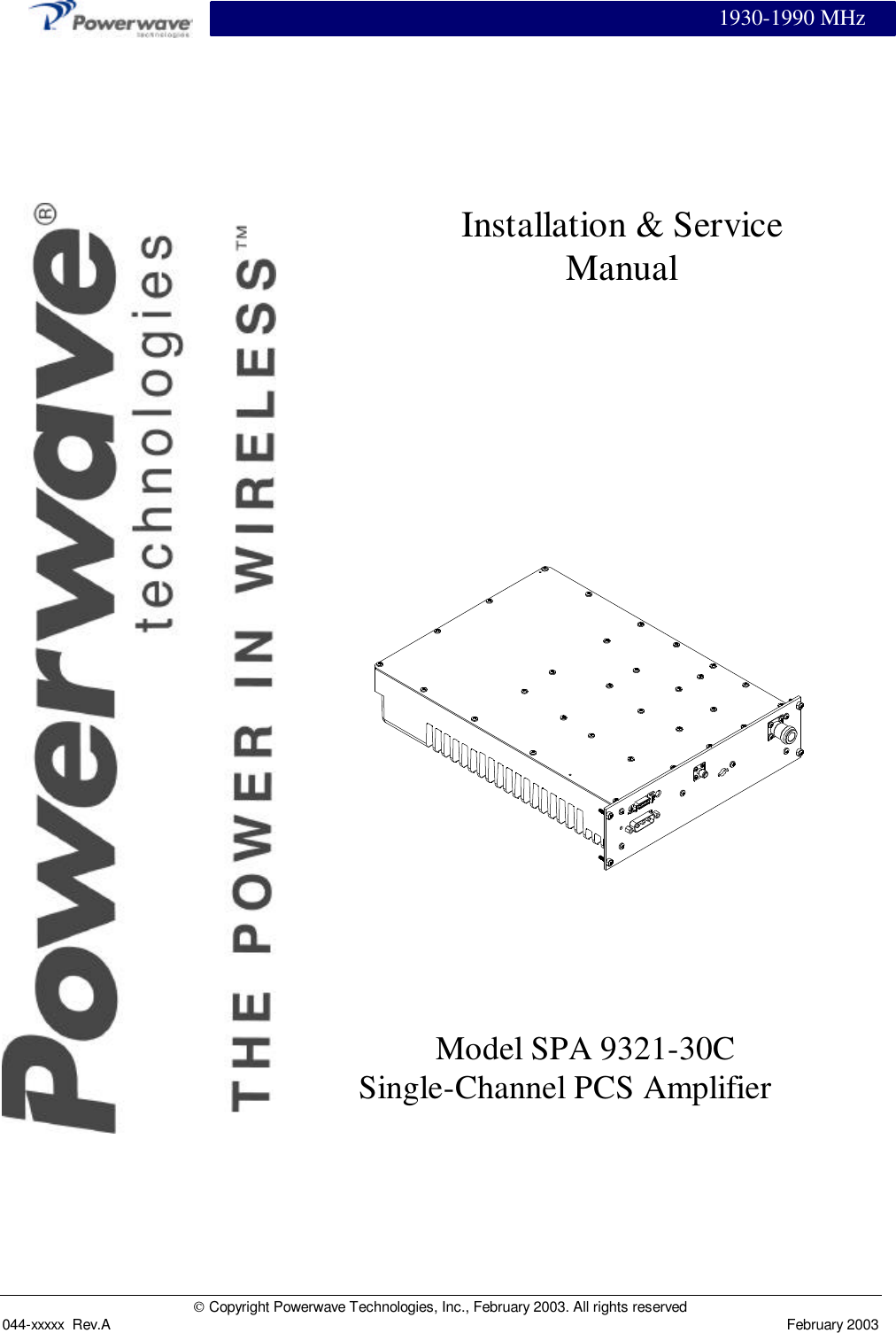
Powerwave Technologies 5JS0065 Single Channel PCS Power Amplifier User Manual Cover Page1 SPA 9321 30C
Powerwave Technologies Inc Single Channel PCS Power Amplifier Cover Page1 SPA 9321 30C
UserManual.wiki
>
Powerwave Technologies
>
5JS0065 User Manual
>
User Manual
Contents
1.
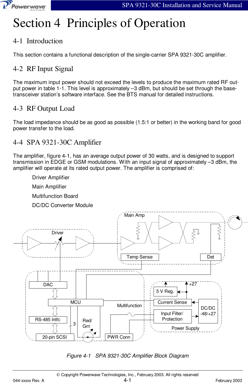
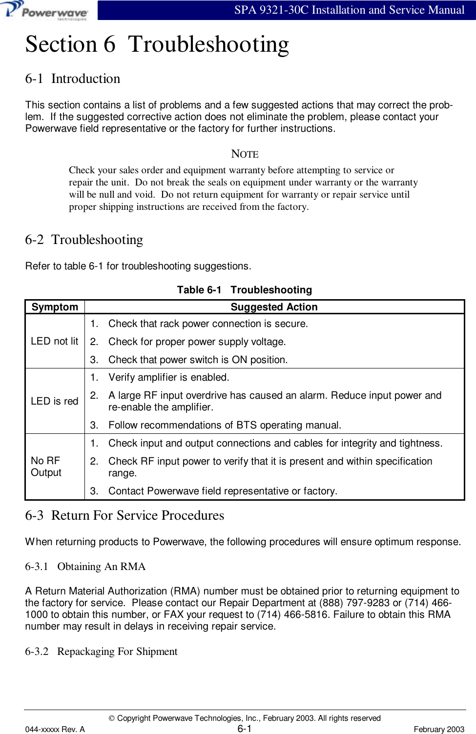
User Manual
2.
Users Manual
User Manual
Navigation menu
Upload a User Manual
Namespaces
Wiki Guide
HTML
PDF
Info
Views
User Manual
Discussion / Help
Navigation