Powerwave Technologies 5JS0065 Single Channel PCS Power Amplifier User Manual Cover Page1 SPA 9321 30C
Powerwave Technologies Inc Single Channel PCS Power Amplifier Cover Page1 SPA 9321 30C
Contents
- 1. User Manual
- 2. Users Manual
User Manual

1930-1990 MHz
Copyright Powerwave Technologies, Inc., February 2003. All rights reserved
044-xxxxx Rev.A February 2003
Model SPA 9321-30C
Single-Channel PCS Amplifier
Installation & Service
Manual

SPA 9321-30C Installation and Service Manual
Copyright Powerwave Technologies, Inc., February 2003. All rights reserved
044-xxxxx Rev. A ii February 2003
February 2003
Powerwave Technologies, Inc. Tel: (714) 466-1000
1801 East St. Andrew Place (888) 797-9283
Santa Ana, CA 92705 Fax: (714) 466-5800
Web Site: www.powerwave.com
© 2003 Powerwave Technologies Incorporated. All rights reserved.
Powerwave Technologies, and the Powerwave logo are registered trademarks
Powerwave Technologies, Inc. reserves the right to make changes to the documentation and
equipment, including but not limited to component substitution and circuitry changes. Changes
that impact this manual may subsequently be incorporated in a later revision of this manual.

SPA 9321-30C Installation and Service Manual
Copyright Powerwave Technologies, Inc., February 2003. All rights reserved
044-xxxxx Rev. A February 2003
iii
Table Of Contents
Par. Section 1 Page
No. General Description No.
1-1 Introduction............................................................................................................................. 1-1
1-2 General Description................................................................................................................. 1-1
1-3 Functional and Physical Specifications .................................................................................... 1-1
1-4 Equipment Changes................................................................................................................. 1-1
Section 2
Installation
2-1 Introduction............................................................................................................................. 2-1
2-2 Electrical Service Recommendations ....................................................................................... 2-1
2-3 Unpacking and Inspection ....................................................................................................... 2-1
2-4 Installation Instructions........................................................................................................... 2-2
2-5 Amplifier Module Connectors.................................................................................................. 2-2
2-5.1 Data I/O Connector ................................................................................................................. 2-3
2-5.2 Amplifier RF Connectors......................................................................................................... 2-4
2-5.3 DC Power Connector............................................................................................................... 2-4
Section 3
Operating Instructions
3-1 Introduction............................................................................................................................. 3-1
3-2 Location and Function of Amplifier Indicators......................................................................... 3-1
3-3 Initial Start-Up and Operating Procedures ............................................................................... 3-1
Section 4
Principles of Operation
4-1 Introduction............................................................................................................................. 4-1
4-2 RF Input Signal....................................................................................................................... 4-1
4-3 RF Output Load....................................................................................................................... 4-1
4-4 SPA 9321-30C Amplifier ........................................................................................................ 4-1
4-4.1 Driver Amplifier...................................................................................................................... 4-2
4-4.2 Main Amplifier ....................................................................................................................... 4-2
4-4.3 Power Distribution................................................................................................................... 4-2
4-4.4 Multifunction Board ................................................................................................................ 4-2
Section 5
Maintenance
5-1 Periodic Maintenance .............................................................................................................. 5-1

SPA 9321-30C Installation and Service Manual
Copyright Powerwave Technologies, Inc., February 2003. All rights reserved
044-xxxxx Rev. A February 2003
iv
Section 6
Troubleshooting
6-1 Introduction............................................................................................................................. 6-1
6-2 Trouble shooting...................................................................................................................... 6-1
6-3 Return for Service Procedures.................................................................................................. 6-1
6-3.1 Obtaining an RMA.................................................................................................................. 6-1
6-3.2 Repackaging for Shipment....................................................................................................... 6-1
List Of Illustrations
Figure Page
No. No.
1-1 SPA 9321-30C Amplifier ........................................................................................................ 1-3
2-1 SPA 9321-30C Front Panel View............................................................................................. 2-2
2-2 Data I/O Connector ................................................................................................................. 2-3
2-3 DC Power Connector............................................................................................................... 2-4
3-1 Front Panel Indicators ............................................................................................................. 3-1
4-1 SPA 9321-30C Amplifier Block Diagram................................................................................ 4-1
List Of Tables
Table Page
No. No.
1-1 SPA 9321-30C Single-Channel PCS Amplifier Functional Specifications................................ 1-2
2-1 Data I/O Connector Pin Definition........................................................................................... 2-3
2-2 Amplifier RF Connector Definition ......................................................................................... 2-4
2-3 DC Power Connector Definition ............................................................................................. 2-4
6-1 Troubleshooting....................................................................................................................... 6-1

SPA 9321-30C Installation and Service Manual
C
Co
op
py
yr
ri
ig
gh
ht
t
P
Po
ow
we
er
rw
wa
av
ve
e
T
Te
ec
ch
hn
no
ol
lo
og
gi
ie
es
s,
,
I
In
nc
c.
.,
,
F
Fe
eb
br
ru
ua
ar
ry
y
2
20
00
03
3.
.
A
Al
ll
l
r
ri
ig
gh
ht
ts
s
r
re
es
se
er
rv
ve
ed
d
A
Al
ll
l
s
sp
pe
ec
ci
if
fi
ic
ca
at
ti
io
on
ns
s
a
ar
re
e
s
su
ub
bj
je
ec
ct
t
t
to
o
c
ch
ha
an
ng
ge
e
w
wi
it
th
ho
ou
ut
t
n
no
ot
ti
ic
ce
e.
.
C
Co
on
nt
ta
ac
ct
t
t
th
he
e
f
fa
ac
ct
to
or
ry
y
f
fo
or
r
c
co
om
mp
pl
le
et
te
e
p
pe
er
rf
fo
or
rm
ma
an
nc
ce
e
d
da
at
ta
a.
.
044-xxxxx Rev. A 1-1February 2003
Section 1 General Description
1-1 Introduction
This manual contains information and procedures for installation, operation, and maintenance of
Powerwave’s SPA 9321-30C (Nortel Model No. NTQA50GA) single-channel PCS amplifier. The
manual is organized into six sections as follows:
Section 1. General Description
Section 2. Installation
Section 3. Operating Instructions
Section 4. Principles of Operation
Section 5. Maintenance
Section 6. Troubleshooting
1-2 General Description
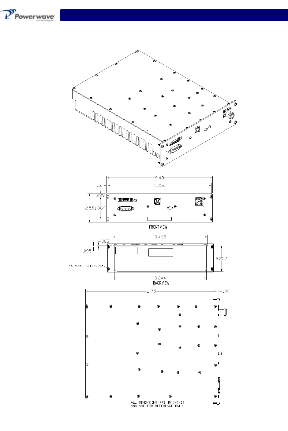
The SPA 9321-30C (see figure 1-1) is a single-channel power amplifier that operates in the 60
MHz frequency band from 1930 MHz to 1990 MHz. It is designed for use in an amplifier system
that is modular in design, and is ideally suited for use in GSM/EDGE base stations. The amplifier
is capable of transmitting at 30 watts of power in either GSM or EDGE modulation. All
solid-state, the amplifier is designed to provide trouble-free operation with minimum mainte-
nance. The system's modular construction and unique and highly effective operational status and
fault monitoring circuitry help minimize downtime. The turn-on and turn-off sequences of volt-
ages are fully automatic, as is overload protection.
Each amplifier module has an I/O connector that allows the host system to monitor the amplifier
module performance. Primary power for the amplifier is –48 Vdc. The amplifier has an integrated
heat sink for cooling.
1-3 Functional And Physical Specifications
Functional and physical specifications for the amplifier are listed in table 1-1.
1-4 Equipment Changes
Powerwave Technologies, Inc. reserves the right to make minor changes to the equipment, in-
cluding but not necessarily limited to component substitution and circuitry changes. Changes that
impact this manual may subsequently be incorporated in a later revision of this manual.
SPA 9321-30C Installation and Service Manual
C
Co
op
py
yr
ri
ig
gh
ht
t
P
Po
ow
we
er
rw
wa
av
ve
e
T
Te
ec
ch
hn
no
ol
lo
og
gi
ie
es
s,
,
I
In
nc
c.
.,
,
F
Fe
eb
br
ru
ua
ar
ry
y
2
20
00
03
3.
.
A
Al
ll
l
r
ri
ig
gh
ht
ts
s
r
re
es
se
er
rv
ve
ed
d
A
Al
ll
l
s
sp
pe
ec
ci
if
fi
ic
ca
at
ti
io
on
ns
s
a
ar
re
e
s
su
ub
bj
je
ec
ct
t
t
to
o
c
ch
ha
an
ng
ge
e
w
wi
it
th
ho
ou
ut
t
n
no
ot
ti
ic
ce
e.
.
C
Co
on
nt
ta
ac
ct
t
t
th
he
e
f
fa
ac
ct
to
or
ry
y
f
fo
or
r
c
co
om
mp
pl
le
et
te
e
p
pe
er
rf
fo
or
rm
ma
an
nc
ce
e
d
da
at
ta
a.
.
044-xxxxx Rev. A 1-2February 2003
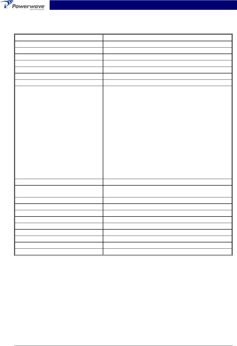
Table 1-1 SPA 9321-30C Single-Channel PCS Amplifier Functional Specifications
Frequency Range 1930-1990 MHz
Nominal Input Power -3.2 dBm
Total Output Power 30 watts maximum
RF Gain at 1960 MHz 48 +/- 0.5 dB
Gain Variation Over All Conditions: ±2.0 dB
Output Protection: Mismatch Protected
Input Port Return Loss: -16 dB (Min)
Out of Band Spurious: -50 dBc (max)
Spectral Mask Frequency Removed From Carrier GSM EDGE
200 kHz -30 dBc -30
dBc
250 kHz -33 dBc -33
dBc
400 kHz -60 dBc -56
dBc
600 kHz -70 dBc -70
dBc
1200 kHz -73 dBc -73
dBc
1800 kHz -75 dBc -75
dBc
6000 kHz -80 dBc -80
dBc
Duty Cycle: Continuous
DC Input Power: -48 VDC; 3.75 amps typical; 4.8 amps max.
-36 to –60 VDC, 180 watts typical; 230 watts max.
Heat Dissipation 512 BTUs typical
Operating Temperature: 0 ºC. to +60 ºC.
Storage Temperature: -40 ºC. to +75 ºC.
Operating Humidity: 5 % - 95 % Relative Humidity (Noncondensing)
Storage Humidity: 5 % - 95 % Relative Humidity (Noncondensing)
RF Input / Output Connector SMA Female (Input) / Type N Female (Output)
DC Power Connector 3-Pin D-Subminiature (20 A Contacts)
Data I/O Connector 20-Pin SCSI
Dimensions: 2.55” High, 9.48” Wide, 11.85” Deep
SPA 9321-30C Installation and Service Manual
C
Co
op
py
yr
ri
ig
gh
ht
t
P
Po
ow
we
er
rw
wa
av
ve
e
T
Te
ec
ch
hn
no
ol
lo
og
gi
ie
es
s,
,
I
In
nc
c.
.,
,
F
Fe
eb
br
ru
ua
ar
ry
y
2
20
00
03
3.
.
A
Al
ll
l
r
ri
ig
gh
ht
ts
s
r
re
es
se
er
rv
ve
ed
d
A
Al
ll
l
s
sp
pe
ec
ci
if
fi
ic
ca
at
ti
io
on
ns
s
a
ar
re
e
s
su
ub
bj
je
ec
ct
t
t
to
o
c
ch
ha
an
ng
ge
e
w
wi
it
th
ho
ou
ut
t
n
no
ot
ti
ic
ce
e.
.
C
Co
on
nt
ta
ac
ct
t
t
th
he
e
f
fa
ac
ct
to
or
ry
y
f
fo
or
r
c
co
om
mp
pl
le
et
te
e
p
pe
er
rf
fo
or
rm
ma
an
nc
ce
e
d
da
at
ta
a.
.
044-xxxxx Rev. A 1-3February 2003
Figure 1-1. SPA 9321-30C Amplifier
All dimensions are in inches
And are for reference only

SPA 9321-30C Installation and Service Manual
Copyright Powerwave Technologies, Inc., February 2003. All rights reserved
044-xxxxx Rev. A2-1February 2003
Section 2 Installation
2-1 Introduction
This section contains installation recommendations, unpacking, inspection, and installation in-
structions for the SPA 9321-30C single channel PCS amplifier. Carefully read all material in this
section prior to equipment unpacking or installation. Also read and review the operating proce-
dures in Section 3 prior to installing the equipment. It is important that the licensee perform these
tasks correctly and in good faith. If applicable, carefully read the Federal Communications
Commission (FCC) rules to determine how they apply to your installation. DON'T TAKE
CHANCES WITH YOUR LICENSE.
2-2 Electrical Service Recommendations
Powerwave Technologies recommends that proper AC line conditioning and surge suppression
be provided on the primary AC input to the -48 Vdc power source. All electrical service should be
installed in accordance with the National Electrical Code, any applicable state or local codes, and
good engineering practice. Special consideration should be given to lightning protection of all
systems in view of the vulnerability of most transmitter sites to lightning. Lightning arrestors are
recommended in the service entrance. Straight, short ground runs are recommended. The elec-
trical service must be well grounded.
The amplifier has an internal fuse, so a failure in one does not shut off the whole installation.
2-3 Unpacking And Inspection
This equipment has been operated, tested and calibrated at the factory. Only in the event of se-
vere shocks or other mistreatment should any substantial readjustment be required. Carefully
open the container(s) and remove the amplifier module(s). Retain all packing material that can
be reassembled in the event that the unit must be returned to the factory.
CAUTION
Exercise care in handling equipment during inspection to prevent damage caused by
rough or careless handling.
Visually inspect the amplifier module for damage that may have occurred during shipment.
Check for evidence of water damage, bent or warped chassis, or loose screws or nuts. Inspect
the front panel for bent connector pins. If the equipment is damaged, a claim should be filed with
the carrier once the extent of any damage is assessed. We cannot stress too strongly the im-
portance of IMMEDIATE careful inspection of the equipment and the subsequent IMMEDIATE
filing of the necessary claims against the carrier if necessary. If possible, inspect the equipment
in the presence of the delivery person. If the equipment is damaged, the carrier is your first area
of recourse. If the equipment is damaged and must be returned to the factory, write or phone for
a return authorization. Powerwave may not accept returns without a return authorization. Claims
for loss or damage may not be withheld from any payment to Powerwave, nor may any payment
due be withheld pending the outcome thereof. WE CANNOT GUARANTEE THE FREIGHT
CARRIER'S PERFORMANCE.
SPA 9321-30C Installation and Service Manual
Copyright Powerwave Technologies, Inc., February 2003. All rights reserved
044-xxxxx Rev. A2-2February 2003
2-4 Installation Instructions (Refer to figures 1-1 and 2-1)
The SPA 9321-30C is intended for installation in a Restricted Access Location.
The SPA 9321-30C amplifier module is designed for installation in a subrack that permits access
to the amplifier’s front panel for connection of DC power, RF, and monitor cables.
To install the amplifier proceed as follows:
1. Install amplifier in the BTS rack and secure in place.
2. Connect the amplifier front panel RF Out (Type-N) connector to the antenna cable.
3. Connect the amplifier front panel RF In (Type-SMA) connector to the transceiver output(s).
4. Connect the BTS 20-pin Data I/O cable to the amplifier. Refer to section 2-5.1.
WARNING
Turn off external DC power before connecting DC power cables. Verify that the
amplifier is terminated into a proper 50 Ohm load.
5. Connect the DC power cable to the rack and amplifier. Refer to section 2-5.3.
6. Check your work before applying DC voltage to the system. Make certain all connections
are tight and correct.
7. Measure DC input voltage. DC input voltage should be -36 to –60 VDC. If the DC input volt-
age is above or below the limits, call and consult Powerwave before you turn on your ampli-
fier system.
8. Refer to section 3 for initial turn-on and checkout procedures.
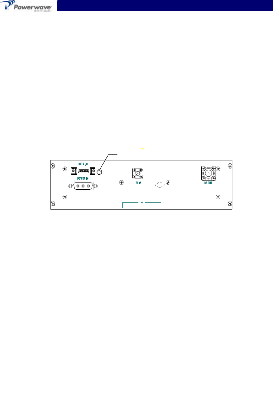
2-5 Amplifier Module Connectors
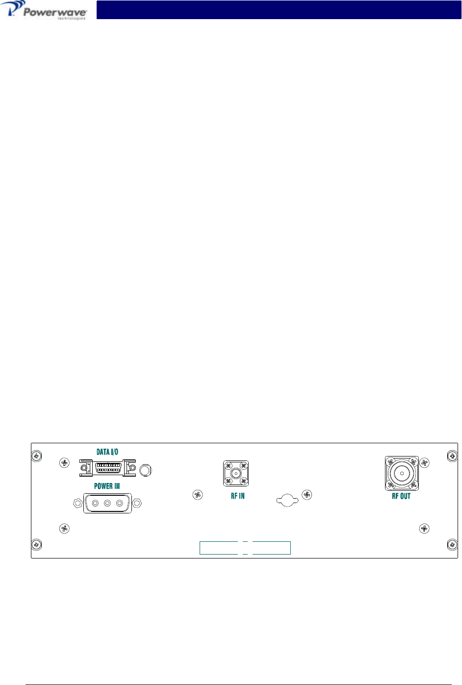
The amplifier has four connectors on the front of the module. These include a SCSI connector
which provides the data I/O connections, SMA female RF input, Type N female RF output, and
3-pin high current contact DC input connectors. Refer to figure 2-1. Each is fully described in the
paragraphs that follow.
Figure 2-1 SPA 9321-30C Front Panel View
SPA 9321-30C Installation and Service Manual
Copyright Powerwave Technologies, Inc., February 2003. All rights reserved
044-xxxxx Rev. A2-3February 2003
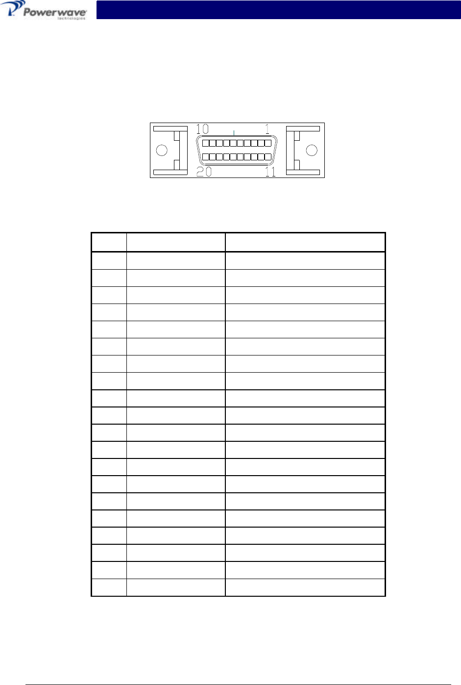
2-5.1 Data I/O Connector
The amplifier has a separate remote alarm and control connector that may be used by the host
system to monitor and control the individual amplifier modules. The status, alarm, and control
connections on the amplifier connector are made through a 20-pin SCSI connector (figure 2-2)
and are listed and described in table 2-1.
Figure 2-2 Data I/O Connector (on Front Panel)
Table 2-1 Data I/O Connector Pin Definition
Pin Function Description
1Ground Ground
2Ground Ground
3Synchro Signal + Synchro Signal from TRX
4UART TX + Information Exchange (TRX to PA)
5Manual Control To Set PA in Test Mode
6Not Connected
7UART RX + Information Exchange (PA to TRX)
8Not Connected
9Not Connected
10 Not Connected
11 Ground Ground
12 Ground Ground
13 Synchro Signal - Synchro Signal from TRX
14 UART TX - Information Exchange (TRX to PA)
15 Not Connected
16 Not Connected
17 UART RX - Information Exchange (PA to TRX)
18 Not Connected
19 Not Connected
20 Not Connected
SPA 9321-30C Installation and Service Manual
Copyright Powerwave Technologies, Inc., February 2003. All rights reserved
044-xxxxx Rev. A2-4February 2003
2-5.2 Amplifier RF Connectors
The amplifier has two RF connectors. The RF Input connector is a SMA female. The input power
on this port should not exceed the level specified in table 1-1. The RF Output connector is Type
N female. They are listed and described in table 2-2.
Table 2-2 Amplifier RF Connector Definition
Function Description
RF Input SMA Female
RF Output Type N Female
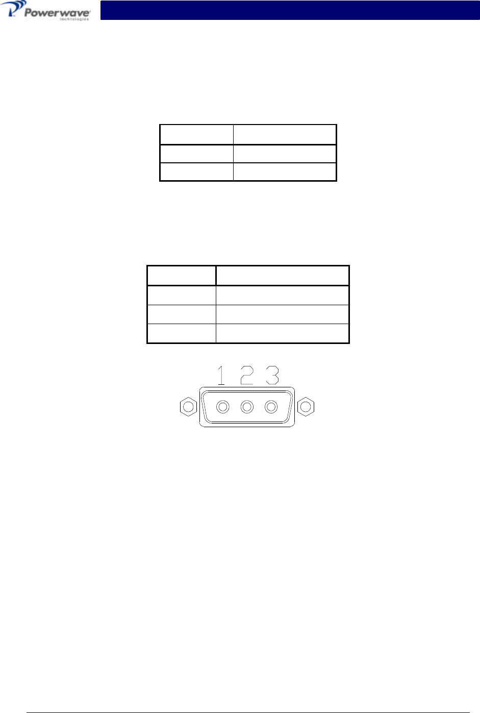
2-5.3 DC Power Connector
The DC power connector is a three-pin high current contact D-subminiature connector. The pin
configuration is listed in table 2-3 and shown in figure 2-3.
Table 2-3 DC Power Connector Definition
Pin Description
1-48 V
2Chassis Ground
3Battery Return
Figure 2-3 DC Power Connector
SPA 9321-30C Installation and Service Manual
Copyright Powerwave Technologies, Inc., February 2003. All rights reserved
044-xxxxx Rev. A3-1February 2003
Section 3 Operating Instructions
3-1 Introduction
This section contains operating instructions for the single channel PCS amplifier system.
3-2 Location And Function Of Amplifier Indicators
The front panel LED is located to the right of the 20-pin Data connector and indicates the ampli-
fier status.
• Green means the amplifier is operating properly.
• Red indicates an alarm or off condition.
The nature of the alarm can only be determined through the software interface of the Base-
Transceiver System (BTS). Please consult the BTS manual for details on monitoring amplifier
status.
Figure 3-1 Front Panel Indicators
3-3 Initial Start-Up And Operating Procedures
To perform the initial start-up, proceed as follows:
1. Verify that all input and output cables are properly connected.
CAUTION
Before applying power, make sure that the input and output of the amplifier are
properly terminated at 50 ohms. Do not operate the amplifier without a load
attached. Refer to table 1-1 for input power requirements. Excessive input power
may damage the amplifier
NOTE
The output coaxial cable between the amplifier and the antenna must be 50 ohm
coaxial cable. Use of any other cable will distort the output.
2. Turn on supply that provides -48 Vdc to the amplifier system. Do not apply an RF signal to
the amplifier system
3. Verify that the LED is lit and the color Green.
4. Turn on external exciter/transceiver and apply RF input signals. Adjust the input power to
achieve the desired output power. Refer to the BTS manual for instructions on performing
this step.
Front Panel Status Indicator
SPA 9321-30C Installation and Service Manual
Copyright Powerwave Technologies, Inc., February 2003. All rights reserved
044-xxxxx Rev. A4-1February 2003
Section 4 Principles of Operation
4-1 Introduction
This section contains a functional description of the single-carrier SPA 9321-30C amplifier.
4-2 RF Input Signal
The maximum input power should not exceed the levels to produce the maximum rated RF out-
put power in table 1-1. This level is approximately –3 dBm, but should be set through the base-
transceiver station’s software interface. See the BTS manual for detailed instructions.
4-3 RF Output Load
The load impedance should be as good as possible (1.5:1 or better) in the working band for good
power transfer to the load.
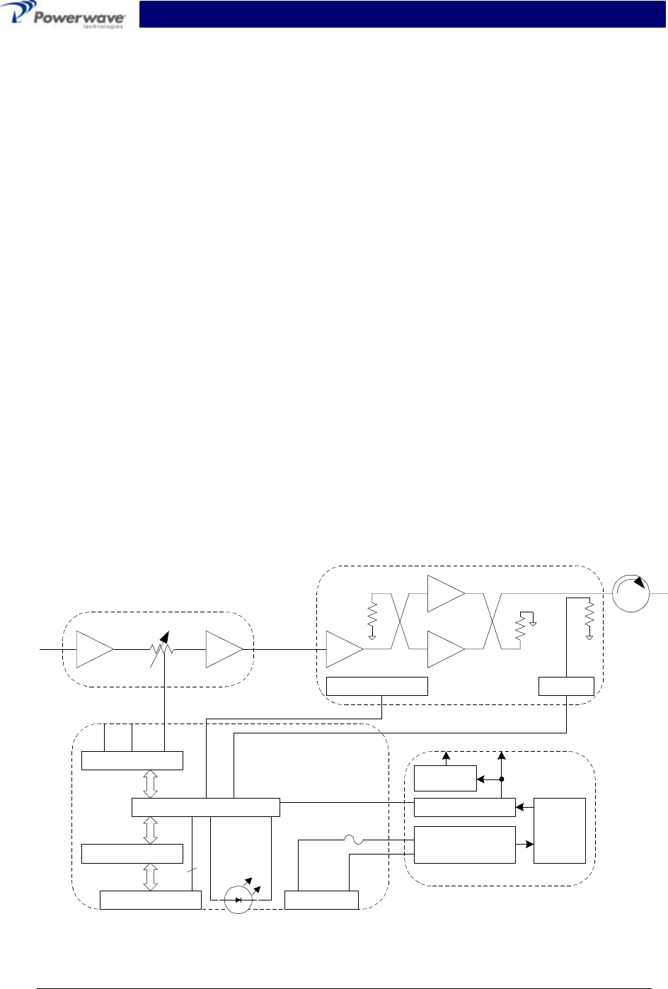
4-4 SPA 9321-30C Amplifier
The amplifier, figure 4-1, has an average output power of 30 watts, and is designed to support
transmission in EDGE or GSM modulations. With an input signal of approximately –3 dBm, the
amplifier will operate at its rated output power. The amplifier is comprised of:
Driver Amplifier
Main Amplifier
Multifunction Board
DC/DC Converter Module
Multifunction
Main Amp
Temp Sense Det
Driver
DAC
MCU
RS-485 Intfc
20-pin SCSI
3
PWR Conn
Red/
Grn
Input Filter/
Protection
Current Sense
DC/DC
-48/+27
5 V Reg.
Power Supply
+27
Figure 4-1 SPA 9321-30C Amplifier Block Diagram

SPA 9321-30C Installation and Service Manual
Copyright Powerwave Technologies, Inc., February 2003. All rights reserved
044-xxxxx Rev. A4-2February 2003
4-4.1 Driver Amplifier
The driver amplifier is a three-stage amplifier which provides approximately 23 dB of gain in the
60 MHz frequency band from 1930 to 1990 MHz. The amplifier is mounted directly on a heat
sink, which is temperature monitored by a thermal sensor.
4-4.2 Main Amplifier
The main amplifier is a two-stage Class AB amplifier with approximately 26 dB gain and a P1dB
of +50 dBm. The amplifier’s output is protected from output mismatches. The amplifier is de-
signed to meet spectral mask requirements for GSM and EDGE signals when operated up to
+45.2 dBm. The amplifier is mounted directly on a heat sink, which is temperature monitored by
a thermal sensor.
4-4.3 Power Distribution
The amplifier module operates on a –48 VDC nominal power supply consuming 3.75 amps or
less (typically) current at full power. A DC/DC converter to supply internal circuitry with +27 VDC
and +5 VDC.
4-4.4 Multifunction Board
The multifunction board enables communication between the amplifier and the base-transceiver
station in which it is installed, and stores information about the amplifier. The multifunction board
also monitors several amplifier performance parameters and reports output power so that the
BTS can maintain the output power within specified limits. When these parameters are beyond
acceptable levels, the amplifier will alarm.
The alarms are:
Temperature Alarm - If the internal temperature reaches 90°C, the PA shuts down and
communicates an alarm through the digital interface.
DC/DC Alarm - If the output voltage of the converter falls below 23.5V, the PA shuts down
and communicates an alarm through the digital interface.
Over-current Alarm - If the output current of the DC/DC converter goes above a nominal
threshold (7.5 A), the PA shuts down and communicates an alarm through the digital
interface.
Communication Alarm - If the serial interface detects an error in transmission (parity, over-
run, framing), an alarm is sent for one burst only during the very next burst. The PA
operation is not affected.

SPA 9321-30C Installation and Service Manual
Copyright Powerwave Technologies, Inc., February 2003. All rights reserved
044-xxxxx Rev. A5-1February 2003
Section 5 Maintenance
5-1 Introduction
The amplifier is designed to be operated without any required periodic maintenance other than
maintenance which may be recommended by the manufacturer of the BTS. Please consult your
BTS manual for guidance.

SPA 9321-30C Installation and Service Manual
Copyright Powerwave Technologies, Inc., February 2003. All rights reserved
044-xxxxx Rev. A6-1February 2003
Section 6 Troubleshooting
6-1 Introduction
This section contains a list of problems and a few suggested actions that may correct the prob-
lem. If the suggested corrective action does not eliminate the problem, please contact your
Powerwave field representative or the factory for further instructions.
NOTE
Check your sales order and equipment warranty before attempting to service or
repair the unit. Do not break the seals on equipment under warranty or the warranty
will be null and void. Do not return equipment for warranty or repair service until
proper shipping instructions are received from the factory.
6-2 Troubleshooting
Refer to table 6-1 for troubleshooting suggestions.
Table 6-1 Troubleshooting
Symptom Suggested Action
LED not lit
1. Check that rack power connection is secure.
2. Check for proper power supply voltage.
3. Check that power switch is ON position.
LED is red
1. Verify amplifier is enabled.
2. A large RF input overdrive has caused an alarm. Reduce input power and
re-enable the amplifier.
3. Follow recommendations of BTS operating manual.
No RF
Output
1. Check input and output connections and cables for integrity and tightness.
2. Check RF input power to verify that it is present and within specification
range.
3. Contact Powerwave field representative or factory.
6-3 Return For Service Procedures
When returning products to Powerwave, the following procedures will ensure optimum response.
6-3.1 Obtaining An RMA
A Return Material Authorization (RMA) number must be obtained prior to returning equipment to
the factory for service. Please contact our Repair Department at (888) 797-9283 or (714) 466-
1000 to obtain this number, or FAX your request to (714) 466-5816. Failure to obtain this RMA
number may result in delays in receiving repair service.
6-3.2 Repackaging For Shipment

SPA 9321-30C Installation and Service Manual
Copyright Powerwave Technologies, Inc., February 2003. All rights reserved
044-xxxxx Rev. A6-2February 2003
To ensure safe shipment of the amplifier, it is recommended that the package designed for the
amplifier be used. The original packaging material is reusable. If it is not available, contact
Powerwave’s Customer Service Department for packing materials and information.