Powerwave Technologies 5JS0066 Power Amplifier User Manual I GENERAL DESCRIPTION
Powerwave Technologies Inc Power Amplifier I GENERAL DESCRIPTION
Contents
- 1. Manual
- 2. Appendix A
Manual

2110-2170 MHz
Operation Manual
G3L-2100-30-B (DC) / G3L-2100-30-C (AC)
Wideband Multi-Carrier Power Amplifier
Operation Manual
2110 MHz – 2170 MHz
044-05133 Rev. A March 2003

G3L-2100-30-B/G3L-2100-30-C Operation Manual
© 2003 Powerwave Technologies Incorporated. All rights reserved.
Powerwave Technologies, and the Powerwave logo are registered trademarks
Powerwave Technologies, Inc. reserves the right to make changes to the documentation and
equipment, including but not limited to component substitution and circuitry changes. Changes
that impact this manual may subsequently be incorporated in a later revision of this manual.
March 2003
Powerwave Technologies, Inc. Tel: (714) 466-1000
1801 E. St. Andrew Place (888) 797-9283
Santa Ana, CA 92705 Fax: (714) 466-5800
Web Site: www.powerwave.com
Copyright Powerwave Technologies, Inc., March 2003. All rights reserved
044-05133 Rev. A ii March 2003

G3L-2100-30-B/G3L-2100-30-C Operation Manual
Section 1 General Description
1-1 Introduction
This manual contains information and procedures for the operation of the model G3L-2100-30-B
and G3L-2100-30-C Wideband (WCDMA) Multi-Carrier Power Amplifier (MCPA). The manual is
organized into the following sections and appendix.
Section 1 General Descri
p
tion
Section 2 O
p
eration
App
endix
A
S
p
ecifications
1-2 General Description
The amplifiers are wideband, linear, feed-forward power amplifiers (WPAs) that operate in the 60
MHz frequency bandwidth from 2110 to 2170 MHz with an instantaneous bandwidth of 20 MHz.
The amplifier provides linear amplification for single or multi-carrier WCDMA signals. The amplifi-
ers communicate with the base station via a TLCI control interface bus; passing alarm and meas-
urement information to the base station and receiving control information from the base station.
1-3 Hardware Interface
There are three groups of interface connections located on the amplifier chassis. These are RF,
power, and control interface (TLCI bus) as described in the paragraphs that follow.
1-3.1 RF
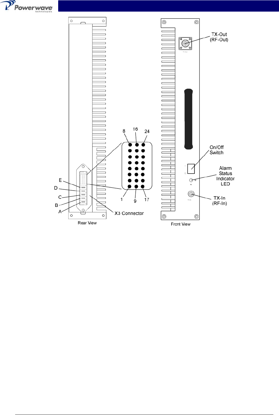
The RF interface is located on the power amplifier front panel consists of the RF-In (TX-In) and
RF-Out (TX-Out) connectors as shown in Figure 1-1.
1-3.2 Power Supply
Power supply voltages (-48 VDC or 230 VAC) from the base station subrack are connected to the
amplifier via connector X3, pins A – D located on the power amplifier rear panel as shown in fig-
ure 1-1. Table 1-1 lists the voltages and descriptions for each pin.
Table 1-1 Primary Power Connections
Signal Group X3 Connector
Pin
Signal Name Description
D -48VDC DC Minus (isolated from amplifier
chassis)
DC
E +48VDC DC Plus (isolated from amplifier chas-
sis)
A L AC Phase (isolated from amplifier
chassis)
B N AC Zero (isolated from amplifier chas-
sis)
AC
C PE AC Protective Ground (connected to
chassis)
Copyright Powerwave Technologies, Inc., March 2003. All rights reserved
044-05133 Rev. A 1-1 March 2003

G3L-2100-30-B/G3L-2100-30-C Operation Manual
1-3.3 TLCI Bus Communications
The purpose of the TCLI bus is to provide a communications interface between the power ampli-
fier and base station. The bus is connected from the base station subrack to the X3 connector
located on the power amplifier rear panel as shown in figure 1-1. Table 1-2 lists the signal names
and descriptions for each pin of the 24-pin connector.
Table 1-2 TLCI Bus Connections
Signal
Group
X3 Connector Pin Signal Name Description
2 AXMTP
3 AXMTN
18 ARCVP
TLCI
19 ARCVN
Ethernet, 10BASE-T
5 WPA_ID_BIT0 Hard-coded WPA ID
13 WPA_ID_BIT1 BIT0=LSB, BIT!=MSB
WPA ID
21 WPA_ID_BIT2 OPEN=1=Logical High
Gnd=0=Logical Low
1
4
8
9
10
11
12
17
20
GND
24
Ground
Connected to WPA chassis ground
Free 6, 7, 14. 15, 16, 22,
23
Reserved for WPA manufacture
Copyright Powerwave Technologies, Inc., March 2003. All rights reserved
044-05133 Rev. A 1-2 March 2003

G3L-2100-30-B/G3L-2100-30-C Operation Manual
1-4 Alarms
The WPA generates the following alarms and communicates then to the base station via the
TLIC bus:
• VSWR
• Gain
• Temperature
• Over-Drive
• Power Supply
• Linearization
The base station is able to query the current alarm status from the WPA. Fault status is cleared at
unit reset which means that any alarm detected after reset is reported to the base station. The
alarm status always represents existing conditions.
1-4.1 VSWR
The WPA supervises the output (load) VSWR and gives the alarm based on the following limits
as listed in table 1-3.
Table 1-3 VSWR Alarm Limits
VSWR Alarm Status Limits
VSWR alarm ON VSWR at the output>8.5:1 @ phase 0-360º
VSWR alarm OFF VSWR at the output<3.0:1 or when the VSWR alarm is dis-
abled @ phase 0-360º
1-4.2 Gain
The WPA supervises the gain of the unit and gives the gain alarm according to the limits listed in
table 1-4.
Table 1-4 Gain Alarm Limits
Gain Alarm Status Limits
Gain alarm ON Gain deviates more than ±1.5 dB from specified nominal
gain or if the carrier cancellation loop is out of lock, the gain
alarm is activated
Gain alarm OFF Gain is within the specified range or disabled
1-4.3 Temperature
The WPA monitors the internal temperature. The measured temperature must represent the base
plate temperature of the main power amplifier. The alarm is given according to the limits listed in
table 1-5.
Copyright Powerwave Technologies, Inc., March 2003. All rights reserved
044-05133 Rev. A 1-3 March 2003

G3L-2100-30-B/G3L-2100-30-C Operation Manual
Table 1-5 Temperature Alarm Limits
Temperature Alarm Status Limits
Temperature alarm ON Internal base plate temperature is equal or higher
than 92ºC
Temperature alarm OFF Internal base plate temperature decreases more
than 10ºC from the alarm on temperature
1-4.4 Overdrive
The overdrive alarm causes an automatic WPA shutdown.
1-4.5 Power Supply
The WPA monitors the internal DC supply voltages and gives the power supply alarm if any of the
voltages are out of the specified range. This alarm causes an automatic WPA shutdown.
1-4.6 Linearization
In case of poor output signal, the linearization causes an automatic WPA shutdown.
1-5 Status Indicator
The status indicator LED is located on the WPA front panel as shown in figure 1-1. The LED has
tri-color capability: red, yellow, and green. The LED’s blinking frequency is 0.5 – 1 Hz with a duty
cycle of 45 – 55%. The LED indicates the status of the WPA as listed in table 1-6.
Table 1-6 Status Indicator Colors
LED Color WPA Status
Red (stable) Manual main-switch turned
standby and no TCP/UDB con-
nection established
Red (stable) LED lighting period 1.5±
±0
0.
.5
5
s
se
ec
c Manual main-switch turned ON
or WPA is resetting
Yellow (blinking) WPA in self-heating state
Yellow (stable) In startup phase, WPA is in
standby state and before state
change message from WPA
LED state as it was before disconnection TCP/IP connection is lost for
two minutes
Yellow (stable) TCP/IP connection is lost and
WPA is in standby state
Copyright Powerwave Technologies, Inc., March 2003. All rights reserved
044-05133 Rev. A 1-4 March 2003

G3L-2100-30-B/G3L-2100-30-C Operation Manual
1-6 Functional And Physical Specifications
Functional and physical specifications for the model G3L-2100-30-B and G3L-2100-30-C amplifi-
ers are listed in appendix A.
1-7 Equipment Changes
Powerwave Technologies, Inc. reserves the right to make minor changes to the equipment, in-
cluding but not necessarily limited to component substitution and circuitry changes. Changes that
impact this manual may subsequently be incorporated in a later revision of this manual. To that
end, we ask that you, our customer, share with us any information acquired in field situations that
would enhance this manual.
1-8 Ordering Information
Table 1-7 below gives the model numbers and descriptions used when ordering major compo-
nents.
Table 1-7 Major Components
Nokia Model
Number*
PWAV Model Num-
ber*
Manual Number Description
WPAA G3L-2100-30-B 044-05133 30W, 2110 – 2170 MHz amplifier
module (DC)
WPAB G3L-2100-30-C 044-05133 30W, 2110 – 2170 MHz amplifier
module (AC)
* Nokia model number located on front panel. Powerwave Technologies model number located
on rear panel.
Copyright Powerwave Technologies, Inc., March 2003. All rights reserved
044-05133 Rev. A 1-5 March 2003
G3L-2100-30-B/G3L-2100-30-C Operation Manual
Figure 1-1 G3L-2100-30-B and G3L-2100-30-C Front and Rear Views
Copyright Powerwave Technologies, Inc., March 2003. All rights reserved
044-05133 Rev. A 1-6 March 2003

G3L-2100-30-B/G3L-2100-30-C Operation Manual
Section 2 Operation
2-1 Introduction
This section contains operating instructions for the G3L-2100-30-B or G3L-2100-30-C wideband
power amplifier (WPA).
2-2 Initial Start-Up and Operating Procedures
The manual main power supply ON/OFF switch is located on the WPA front panel (refer to figure
1-1 and paragraph 1-5 for status indicator conditions). Turn on the WPA as described in the steps
that follow.
CAUTION
Before applying power, make sure that the input and output of the system is properly
terminated at 50 ohms. Do not operate the system without a load attached. Refer to
appendix A for input power requirements. Excessive input power may damage the
amplifier.
WARNING
Never remove or install coaxial cables on either the subrack input or output port when
the power amplifier is turned on. Operating the power amplifier while disconnecting
and connecting RF cables may damage the equipment and/or cause personal injury.
1. Verify that all input and output RF cables are properly connected. Do not apply an RF signal
to the WPA.
2. Turn on the main manual power supply switch (1=ON, 0=OFF). The WPA will self-test and
initialize (<15 sec), then establish communication with the base station via the TLCI bus.
When completed, the WPA notifies the base station that it is ready to be taken into opera-
tion. The WPA then remains in a standby state until commanded by the base station. The
command received from the base station includes the operating band and based on that
band, the pilot frequency sets to 10 MHz lower than the lowest carrier in the operating band.
NOTE
When the WPA is switched on in temperature conditions below the minimum operat-
ing temperature (-10ºC), self-heating is performed until an acceptable operating tem-
perature exists.
NOTE
The main manual power supply switch is also used to reset the WPA by manually set-
ting the switch to OFF then back to ON.
Copyright Powerwave Technologies, Inc., March 2003. All rights reserved
044-05133 Rev. A 2-1 March 2003

G3L-2100-30-B/G3L-2100-30-C Operation Manual
Appendix A. Specifications
Table A-1 G3L-2100-30-B/30-C Wideband Multicarrier Cellular Amplifier Functional
Specifications
Frequency Range 2110 - 2170 MHz (60 MHz Bandwidth)
Instantaneous Bandwidth 20 MHz *
Total Typical / Maximum Input Power -15.7 - +4.8 / +5.8 dBm
Total Output Power 30 W (44.8 dBm)
Adjacent Channel Leakage Power
Ratio (ACLR) Spectrum Analyzer set-
tings: 30 KHz RBW, 300 KHz VBW,
True RMS detector
ACLR1 <-46dBc@f=fc ±5 MHz
ACLR2 <-51dBc@f=fc ±10 MHz
RF Gain 40 dB +0.5 dB
Gain Flatness: ±0.5 dB
Output Protection: Mismatch Protected
Input Port Return Loss: 18 dB min
Harmonics: Better than -50 dBc
Out of Band Spurious: Better than -60 dBc
Duty Cycle: Continuous
DC Input Power:
G3L-2100-30-B
-48 Vdc nominal, 6.5 amps typical (15 amps max)
Operational -57 Vdc to -60 Vdc (Po derated outside
normal operating range)
AC Input Power:
G3L-2100-30-C
230 Vac nominal, 50/60 Hz, 1.9 amps typical (3 amps
max)
Operational 264 Vac to 300 Vac (Po derated outside
normal operating range)
Operating Temperature: -10 ºC to +50 ºC
Storage Temperature: -40 ºC to +85 ºC
Operating Humidity: 0 % to 80 % Relative Humidity (noncondensing)
Storage Humidity: 0 % to 100 % Relative Humidity (noncondensing)
AC, DC Input, Summary Alarm, Base
Station Communication TLCI Bus:
Elcon Modular Flatpaq tm
RF Input Connector: SMA Female
RF Output Connector: Type N-Female
Power Consumption: DC Version: 310 Watts @ Po = 30 W average power
AC Version: 325 Watts @ Po = 30 W average power
Weight: 28 lbs.
Dimensions: 3.125” High, 16.75” Wide, 14.125” Deep, 15.75” Deep
including connector guides
* The command received from the base station includes the operating band and based on that
band, the pilot frequency sets to 10 MHz lower than the lowest carrier in the operating band.
Copyright Powerwave Technologies, Inc., March 2003. All rights reserved
All specifications are subject to change without notice. Contact the factory for complete performance data.
044-05133 Rev. A A-1 March 2003