Powerwave Technologies 5JS0067 W-CDMA Multi-Channel PCS Amplifier User Manual I GENERAL DESCRIPTION
Powerwave Technologies Inc W-CDMA Multi-Channel PCS Amplifier I GENERAL DESCRIPTION
UserManual.wiki
>
Powerwave Technologies
>
5JS0067 User Manual
User Manual
Navigation menu
Upload a User Manual
Namespaces
Wiki Guide
HTML
PDF
Info
Views
User Manual
Discussion / Help
Navigation
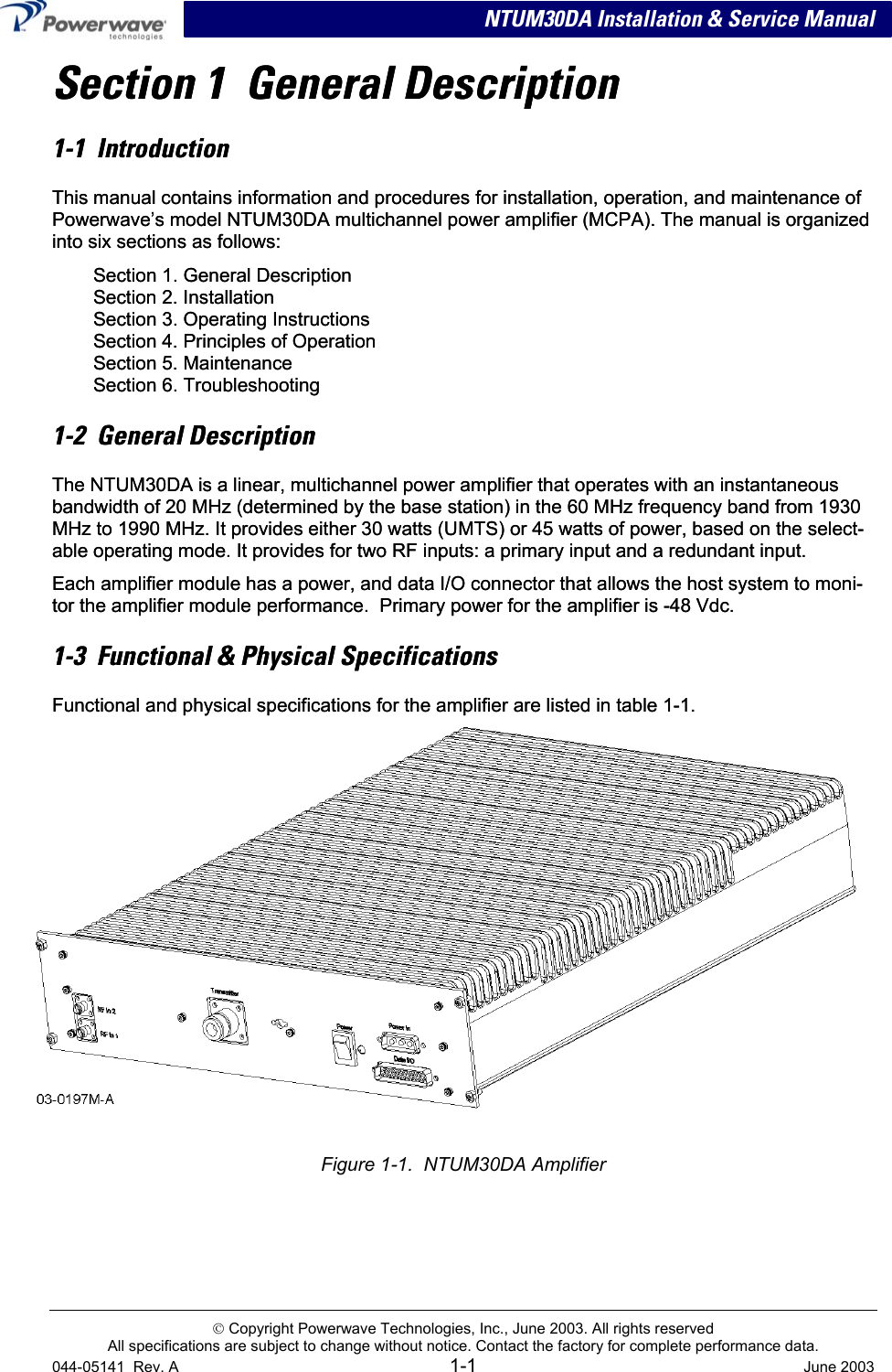
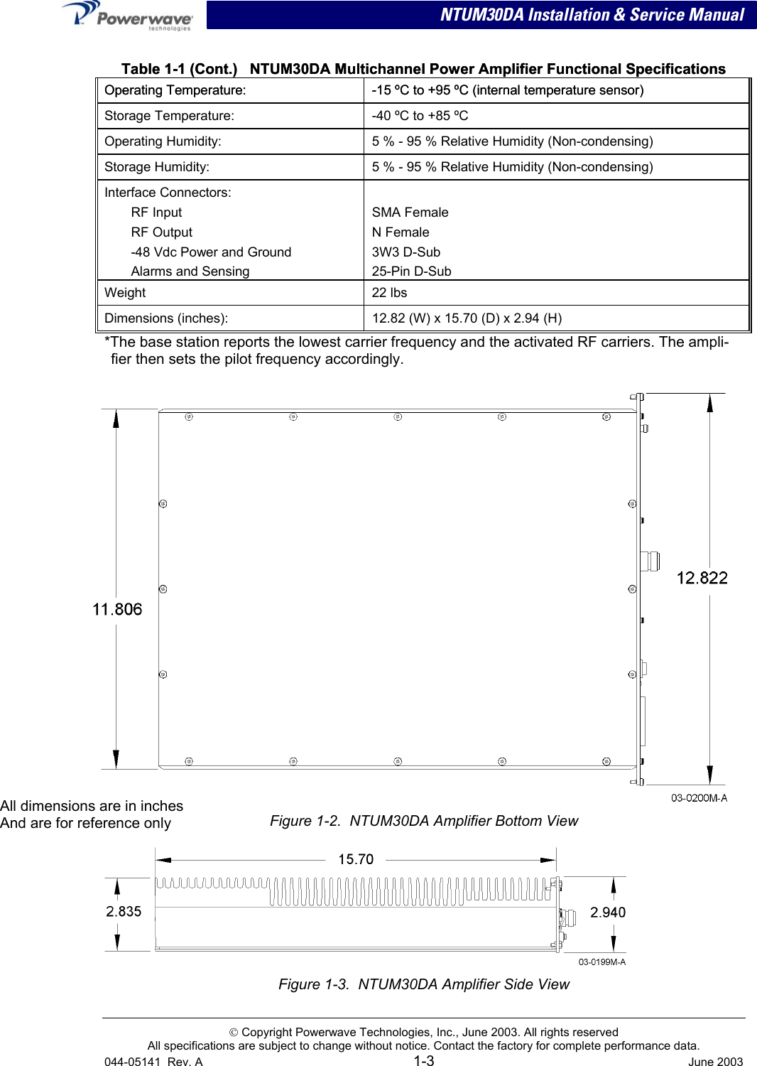
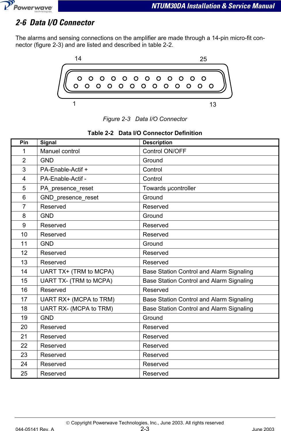
![NTUM30DA Installation & Service Manual Table 1-1 NTUM30DA Multichannel Power Amplifier Functional Specifications Frequency Range 1930-1990 MHz (60 MHz Bandwidth) *Instantaneous Bandwidth 20 MHz Input Power 1.4 dBm without damage (operating); 15 dBm without damage (non-operating) Continuous Average Output Power 45 Watts (46.53 dBm) Mode 1 30 Watts (44.77 dBm) Mode 2 Frequency Offset Fcl: lower frequency center of the emission block. Fcu: upper frequency center of the emission block. ∆F = the frequency gap between the lower or the upper carrier of the emission block and the center of the measurement filter (BW) Max Level dBm Measurement filter BW Fcl- 2.780 MHz< ∆F ≤ Fcl- 2.515 MHz Fcu+ 2.515 MHz≤ ∆F < Fcu+ 2.780 MHz - 16 30 kHz Fcl- 3.515 MHz< ∆F ≤ Fcl- 2.780 MHz Fcu+ 2.780 MHz≤ ∆F < Fcu+ 3.515 MHz [-16-15*(Fo-2.780)] 30 kHz Fcl- 4.0 MHz< ∆F ≤ Fcl- 3.515 MHz Fcu+ 3.515 MHz≤ ∆F < Fcu+ 4.0 MHz -27 30 kHz Spurious Emissions @ Maximum Rated Output Power Fcl- 12.5 MHz< ∆F ≤ Fcl- 4.0 MHz Fcu+4.0 MHz≤ ∆F < Fcu+12.5 MHz -14 1 MHZ RF Gain 46.5 ± 1 dB Output Dynamic Range Mode 1 Mode 2 21.5 dB 19.77 dB Output Protection: Mismatch Protected Input Port Return Loss: < 1.43:1 Max. Frequency band Max Level (dBm) Measurement filter BW 9 kHz ↔ 150 kHz -39 dBm 1 kHz 150 kHz ↔ 30 MHz -39 dBm 10 kHz 30 MHz ↔ 1 GHz -39 dBm 100 kHz 1 GHz ↔ Fc1 - 60 MHz -33 dBm 1 MHz Fcl - 60 MHz ↔ Fcl - 50 MHz -28 dBm 1 MHz Fcl - 50 MHz ↔ Fcl – 12.5 MHz -16 dBm 1 MHz Fcu + 12.5 MHz ↔ Fcu + 50 MHz -16 dBm 1 MHz Fcu + 50 MHz ↔ Fcu + 60 MHz -28 dBm 1 MHz Out of Band Spurious: Fcu + 60 MHz ↔ 12.75 GHz -33 dBm 1 MHZ DC Input Power: Normal voltage range: Extended voltage range: Abnormal voltage range: Power Consumption: Mode 1 Mode 2 Reverse polarity protected -38 V to –58 V -36 V to –38 V and -58 V to –60 V 0 V to –36 V and -60 V to –72 V 375 W max. 300 W max. Copyright Powerwave Technologies, Inc., June 2003. All rights reserved All specifications are subject to change without notice. Contact the factory for complete performance data. 044-05141 Rev. A 1-2 June 2003](https://usermanual.wiki/Powerwave-Technologies/5JS0067/User-Guide-336048-Page-6.png)