Powerwave Technologies 5JS0067 W-CDMA Multi-Channel PCS Amplifier User Manual I GENERAL DESCRIPTION
Powerwave Technologies Inc W-CDMA Multi-Channel PCS Amplifier I GENERAL DESCRIPTION
User Manual

1930-1990 MHz
Installation & Service
Manual
Model NTUM30DA
Multi-Channel PCS Amplifier
Copyright Powerwave Technologies, Inc., June 2003. All rights reserved
044-05141 Rev. A June 2003

NTUM30DA Installation & Service Manual
Copyright Powerwave Technologies, Inc., June 2003. All rights reserved
June 2003
© 2003 Powerwave Technologies Incorporated. All rights reserved.
Powerwave Technologies, and the Powerwave logo are registered trademarks
Powerwave Technologies, Inc. reserves the right to make changes to the documentation and
equipment, including but not limited to component substitution and circuitry changes. Changes
that impact this manual may subsequently be incorporated in a later revision of this manual.
Powerwave Technologies, Inc. Tel: (714) 466-1000
1801 East St. Andrew Place (888) 797-9283
Santa Ana, CA 92705 Fax: (714) 466-5800
Web Site: www.powerwave.com
044-05141 Rev. A ii June 2003

NTUM30DA Installation & Service Manual
Table Of Contents
Par. Section 1 Page
No. General Description No.
1-1 Introduction ..................................................................................................................................................... 1-1
1-2 General Description....................................................................................................................................... 1-1
1-3 Functional and Physical Specifications.................................................................................................... 1-1
Section 2
Installation
2-1 Introduction ..................................................................................................................................................... 2-1
2-2 Electrical Service Recommendations........................................................................................................ 2-1
2-3 Unpacking and Inspection............................................................................................................................ 2-1
2-4 Installation Instructions................................................................................................................................ 2-2
2-5 Power In Connector ....................................................................................................................................... 2-2
2-6 Data I/O Connector......................................................................................................................................... 2-3
2-7 P3: Differential IIC Clock, Receive, & Transmit Connector................................................................... 2-4
2-8 P4: IIC, Power, Alarms, & Controls Connector......................................................................................... 2-4
2-9 P5: IIC, RS485, Power, & Other Signals Connector ................................................................................. 2-6
Section 3
Operating Instructions
3-1 Introduction ..................................................................................................................................................... 3-1
3-2 Initial Start-Up and Operating Procedures ............................................................................................... 3-1
Section 4
Principles of Operation
4-1 Introduction ..................................................................................................................................................... 4-1
4-2 RF Input Signal................................................................................................................................................ 4-1
4-3 RF Output Load ................................................................................................................................................ 4-1
4-4 Amplifier Functional Description................................................................................................................ 4-1
4-4.1 Input Amplifier ................................................................................................................................................ 4-1
4-4.2 1st Loop Phase & Gain.................................................................................................................................... 4-1
4-4.3 Driver Amplifier .............................................................................................................................................. 4-2
4-4.4 Main Amplifier ................................................................................................................................................ 4-2
4-4.5 Multifunction Board....................................................................................................................................... 4-2
4-5 Amplifier Module Cooling ............................................................................................................................ 4-2
4-6 Power Distribution......................................................................................................................................... 4-3
4-7 Amplifier Alarms............................................................................................................................................. 4-3
4-7.1 Minor Alarms................................................................................................................................................... 4-3
4-7.1.1 Main Loop Cancellation Alarm (1st Loop Alarm) ...................................................................................... 4-3
4-7.1.2 Error Loop Cancellation Alarm (2nd Loop Alarm)...................................................................................... 4-4
4-7.1.3 Gain Alarm ....................................................................................................................................................... 4-4
4-7.1.4 Partial Failure of Main Amplifier Alarm (Transistor/Device Fail) ........................................................4-4
4-7.1.5 Over Temperature Warning Alarm.............................................................................................................. 4-4
4-7.1.6 Power Supply Warning Alarm ..................................................................................................................... 4-4
4-7.1.7 High DC Power Consumption Warning Alarm.......................................................................................... 4-4
4-7.2 Major Alarms................................................................................................................................................... 4-5
Copyright Powerwave Technologies, Inc., June 2003. All rights reserved
044-05141 Rev. A June 2003
iii

NTUM30DA Installation & Service Manual
Par. Section 4 Page
No. Principles of Operation (continued) No.
4-7.2.1 Over Temperature Shutdown Alarm........................................................................................................... 4-5
4-7.2.2 Power Supply Shutdown Alarm .................................................................................................................. 4-5
4-7.2.3 High DC Power Consumption Shutdown Alarm ....................................................................................... 4-6
Section 5
Maintenance
5-1 Introduction ..................................................................................................................................................... 5-1
5-2 Periodic Maintenance................................................................................................................................... 5-1
5-3 Field Replacement Of The Module.............................................................................................................. 5-1
Section 6
Troubleshooting
6-1 Introduction ..................................................................................................................................................... 6-1
6-2 Trouble shooting............................................................................................................................................. 6-1
6-3 Return for Service Procedures .................................................................................................................... 6-1
6-3.1 Obtaining an RMA .......................................................................................................................................... 6-1
6-3.2 Repackaging for Shipment ........................................................................................................................... 6-1
List Of Illustrations
Figure Page
No. No.
1-1 NTUM30DA Amplifier .................................................................................................................................... 1-1
1-2 NTUM30DA Amplifier Bottom View............................................................................................................ 1-3
1-3 NTUM30DA Amplifier Side View ................................................................................................................ 1-3
1-4 NTUM30DA Amplifier Front Panel .............................................................................................................. 1-4
2-1 NTUM30DA Amplifier Front Panel .............................................................................................................. 2-2
2-2 Power In Connector ....................................................................................................................................... 2-2
2-3 Data I/O Connector......................................................................................................................................... 2-3
4-1 NTUM30DA Amplifier Block Diagram........................................................................................................ 4-2
4-2 Minor Alarm Reporting Sequence .............................................................................................................. 4-3
4-3 Major Alarm Reporting Sequence .............................................................................................................. 4-5
List Of Tables
Table Page
No. No.
1-1 NTUM30DA Multichannel Power Amplifier Functional Specifications.............................................. 1-2
2-1 Power In Connector Definition .................................................................................................................... 2-2
2-2 Data I/O Connector Definition...................................................................................................................... 2-3
4-1 Alarm Summary .............................................................................................................................................. 4-6
5-1 Periodic Maintenance................................................................................................................................... 5-1
6-1 Troubleshooting.............................................................................................................................................. 6-1
Copyright Powerwave Technologies, Inc., June 2003. All rights reserved
044-05141 Rev. A June 2003
iv
NTUM30DA Installation & Service Manual
Section 1 General Description Section 1 General Description
1-1 Introduction 1-1 Introduction
This manual contains information and procedures for installation, operation, and maintenance of
Powerwave’s model NTUM30DA multichannel power amplifier (MCPA). The manual is organized
into six sections as follows:
This manual contains information and procedures for installation, operation, and maintenance of
Powerwave’s model NTUM30DA multichannel power amplifier (MCPA). The manual is organized
into six sections as follows:
Section 1. General Description
Section 2. Installation
Section 3. Operating Instructions
Section 4. Principles of Operation
Section 5. Maintenance
Section 6. Troubleshooting
Section 1. General Description
Section 2. Installation
Section 3. Operating Instructions
Section 4. Principles of Operation
Section 5. Maintenance
Section 6. Troubleshooting
1-2 General Description 1-2 General Description
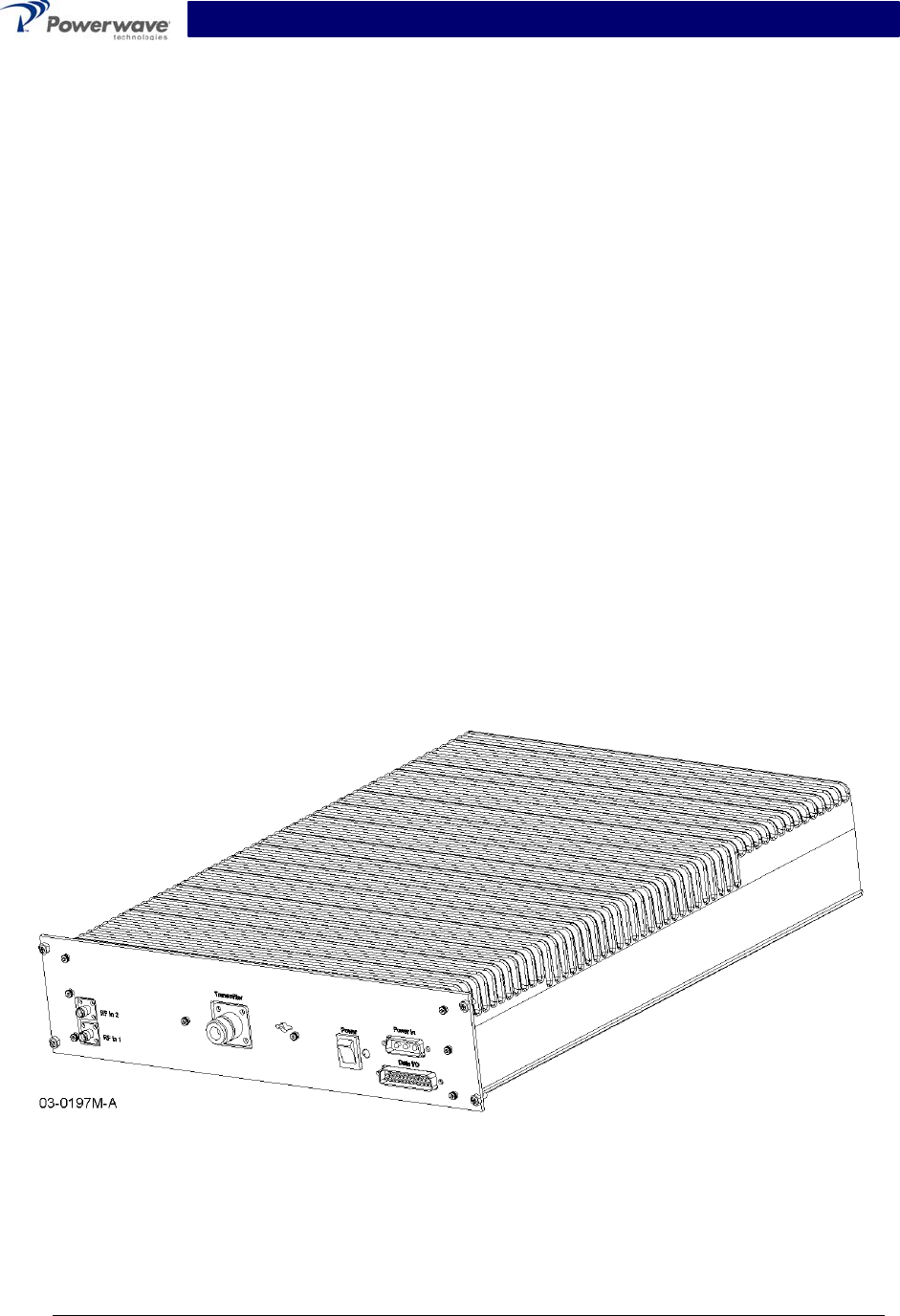
The NTUM30DA is a linear, multichannel power amplifier that operates with an instantaneous
bandwidth of 20 MHz (determined by the base station) in the 60 MHz frequency band from 1930
MHz to 1990 MHz. It provides either 30 watts (UMTS) or 45 watts of power, based on the select-
able operating mode. It provides for two RF inputs: a primary input and a redundant input.
Each amplifier module has a power, and data I/O connector that allows the host system to moni-
tor the amplifier module performance. Primary power for the amplifier is -48 Vdc.
Each amplifier module has a power, and data I/O connector that allows the host system to moni-
tor the amplifier module performance. Primary power for the amplifier is -48 Vdc.
1-3 Functional & Physical Specifications 1-3 Functional & Physical Specifications
Functional and physical specifications for the amplifier are listed in table 1-1. Functional and physical specifications for the amplifier are listed in table 1-1.
Figure 1-1. NTUM30DA Amplifier
Copyright Powerwave Technologies, Inc., June 2003. All rights reserved
All specifications are subject to change without notice. Contact the factory for complete performance data.
044-05141 Rev. A 1-1 June 2003

NTUM30DA Installation & Service Manual
Table 1-1 NTUM30DA Multichannel Power Amplifier Functional Specifications
Frequency Range 1930-1990 MHz (60 MHz Bandwidth)
*Instantaneous Bandwidth 20 MHz
Input Power 1.4 dBm without damage (operating);
15 dBm without damage (non-operating)
Continuous Average Output Power 45 Watts (46.53 dBm) Mode 1
30 Watts (44.77 dBm) Mode 2
Frequency Offset
Fcl: lower frequency center of the emission block.
Fcu: upper frequency center of the emission block.
∆F = the frequency gap between the lower or the upper carrier of the
emission block and the center of the measurement filter (BW)
Max Level
dBm
Measurement
filter BW
Fcl- 2.780 MHz< ∆F ≤ Fcl- 2.515 MHz
Fcu+ 2.515 MHz≤ ∆F < Fcu+ 2.780 MHz - 16 30 kHz
Fcl- 3.515 MHz< ∆F ≤ Fcl- 2.780 MHz
Fcu+ 2.780 MHz≤ ∆F < Fcu+ 3.515 MHz [-16-15*(Fo-2.780)] 30 kHz
Fcl- 4.0 MHz< ∆F ≤ Fcl- 3.515 MHz
Fcu+ 3.515 MHz≤ ∆F < Fcu+ 4.0 MHz -27 30 kHz
Spurious
Emissions @
Maximum Rated
Output Power
Fcl- 12.5 MHz< ∆F ≤ Fcl- 4.0 MHz
Fcu+4.0 MHz≤ ∆F < Fcu+12.5 MHz -14 1 MHZ
RF Gain 46.5 ± 1 dB
Output Dynamic Range
Mode 1
Mode 2
21.5 dB
19.77 dB
Output Protection: Mismatch Protected
Input Port Return Loss: < 1.43:1 Max.
Frequency band Max Level (dBm) Measurement filter BW
9 kHz ↔ 150 kHz -39 dBm 1 kHz
150 kHz ↔ 30 MHz -39 dBm 10 kHz
30 MHz ↔ 1 GHz -39 dBm 100 kHz
1 GHz ↔ Fc1 - 60 MHz -33 dBm 1 MHz
Fcl - 60 MHz ↔ Fcl - 50 MHz -28 dBm 1 MHz
Fcl - 50 MHz ↔ Fcl – 12.5 MHz -16 dBm 1 MHz
Fcu + 12.5 MHz ↔ Fcu + 50 MHz -16 dBm 1 MHz
Fcu + 50 MHz ↔ Fcu + 60 MHz -28 dBm 1 MHz
Out of Band
Spurious:
Fcu + 60 MHz ↔ 12.75 GHz -33 dBm 1 MHZ
DC Input Power:
Normal voltage range:
Extended voltage range:
Abnormal voltage range:
Power Consumption:
Mode 1
Mode 2
Reverse polarity protected
-38 V to –58 V
-36 V to –38 V and -58 V to –60 V
0 V to –36 V and -60 V to –72 V
375 W max.
300 W max.
Copyright Powerwave Technologies, Inc., June 2003. All rights reserved
All specifications are subject to change without notice. Contact the factory for complete performance data.
044-05141 Rev. A 1-2 June 2003

NTUM30DA Installation & Service Manual
Table 1-1 (Cont.) NTUM30DA Multichannel Power Amplifier Functional Specifications Table 1-1 (Cont.) NTUM30DA Multichannel Power Amplifier Functional Specifications
Operating Temperature: Operating Temperature: -15 ºC to +95 ºC (internal temperature sensor) -15 ºC to +95 ºC (internal temperature sensor)
Storage Temperature: -40 ºC to +85 ºC
Operating Humidity: 5 % - 95 % Relative Humidity (Non-condensing)
Storage Humidity: 5 % - 95 % Relative Humidity (Non-condensing)
Interface Connectors:
RF Input
RF Output
-48 Vdc Power and Ground
Alarms and Sensing
SMA Female
N Female
3W3 D-Sub
25-Pin D-Sub
Weight 22 lbs
Dimensions (inches): 12.82 (W) x 15.70 (D) x 2.94 (H)
*The base station reports the lowest carrier frequency and the activated RF carriers. The ampli-
fier then sets the pilot frequency accordingly.
All dimensions are in inches
And are for reference only Figure 1-2. NTUM30DA Amplifier Bottom View
Figure 1-3. NTUM30DA Amplifier Side View
Copyright Powerwave Technologies, Inc., June 2003. All rights reserved
All specifications are subject to change without notice. Contact the factory for complete performance data.
044-05141 Rev. A 1-3 June 2003

NTUM30DA Installation & Service Manual
Figure 1-4. NTUM30DA Amplifier Front Panel
Copyright Powerwave Technologies, Inc., June 2003. All rights reserved
All specifications are subject to change without notice. Contact the factory for complete performance data.
044-05141 Rev. A 1-4 June 2003

NTUM30DA Installation & Service Manual
Section 2 Installation
2-1 Introduction
This section contains unpacking, inspection, and installation instructions and recommendations
for the Model NTUM30DA Multi Channel Power Amplifier. Carefully read all material in this sec-
tion prior to equipment unpacking or installation. Also read and review the operating procedures
in section 3 prior to installing the equipment. It is important that the licensee perform these tasks
correctly and in good faith. If applicable, carefully read the appropriate parts of the Federal Com-
munications Commission (FCC) rules to determine how they apply to your installation. DON'T
TAKE CHANCES WITH YOUR LICENSE.
2-2 Electrical Service Recommendations
Powerwave Technologies recommends that proper AC line conditioning and surge suppression
be provided on the primary AC input to the -48 Vdc power source. All electrical service should be
installed in accordance with the National Electrical Code, any applicable state or local codes, and
good engineering practice. Special consideration should be given to lightning protection of all
systems in view of the vulnerability of most transmitter sites to lightning. Lightning arrestors are
recommended in the service entrance. Straight, short ground runs are recommended. The elec-
trical service must be well grounded.
Each amplifier system should have its own circuit breaker, so a failure in one does not shut off
the whole installation. Circuit breakers should be thermal type, capable of handling the maximum
anticipated inrush current, in a load center with a master switch.
2-3 Unpacking & Inspection
This equipment has been operated, tested and calibrated at the factory. Carefully open the con-
tainer(s) and remove the amplifier module(s). Retain all packing material that can be reassem-
bled in the event that the unit must be returned to the factory.
CAUTION
Exercise care in handling equipment during inspection to prevent damage caused by
rough or careless handling.
Visually inspect the amplifier module for damage that may have occurred during shipment.
Check for evidence of water damage, bent or warped chassis, loose screws or nuts, or extrane-
ous packing material in the connector. If the equipment is damaged, a claim should be filed with
the carrier once the extent of any damage is assessed. We cannot stress too strongly the impor-
tance of IMMEDIATE careful inspection of the equipment and the subsequent IMMEDIATE filing
of the necessary claims against the carrier if necessary. If possible, inspect the equipment in the
presence of the delivery person. If the equipment is damaged, the carrier is your first area of re-
course. If the equipment is damaged and must be returned to the factory, write or phone for a
return authorization. Powerwave may not accept returns without a return authorization. Claims
for loss or damage may not be withheld from any payment to Powerwave, nor may any payment
due be withheld pending the outcome thereof. WE CANNOT GUARANTEE THE FREIGHT CAR-
RIER'S PERFORMANCE
Copyright Powerwave Technologies, Inc., June 2003. All rights reserved
044-05141 Rev. A 2-1 June 2003

NTUM30DA Installation & Service Manual
2-4 Installation Instructions (Refer to figure 1-1)
The NTUM30DA amplifier module is designed for installation on a heatsink that permits access to
the module for connection of the RF cables and the power, alarm, and control connectors.
To install the amplifier proceed as follows:
Figure 2-1 NTUM30DA Amplifier, Front Panel View
1. Install the amplifier and secure in place with appropriate mounting screws. See figure 2-1.
2. Connect the antenna cable to TRANSMITTER female N-type connector.
3. Connect the transceiver output cables to the RF IN female SMA connectors.
WARNING
Turn the front panel Power switch off before connecting the power cable.
4. Connect the power, and data cables to matching Power In and Data I/O connectors. Refer
to paragraphs 2-5 and 2-6 following for appropriate port and pin connections.
5. Check your work before applying DC voltage to the system. Make certain all connections
are tight and correct.
6. Measure primary DC input voltage. DC input voltage should be -48 ±0.5 Vdc. If the DC in-
put voltage is above or below the limits, call and consult Powerwave before you turn on your
amplifier system.
7. Refer to section 3 for initial turn-on and checkout procedures.
2-5 Power In Connector
The -48 Vdc power and ground connections on the amplifier are made through a 3-pin female
D-Sub connector (figure 2-2) and are listed and described in table 2-1.
3 2 1
Figure 2-2 Power In Connector
Table 2-1 Power In Connector Definition
Pin Signal Description
1 -48 V -48 Vdc for MCPA
2 Chassis Gnd Chassis Ground
3 .-48V_RTN -48 Vdc return, grounded to MCPA chassis ground
Copyright Powerwave Technologies, Inc., June 2003. All rights reserved
044-05141 Rev. A 2-2 June 2003
NTUM30DA Installation & Service Manual
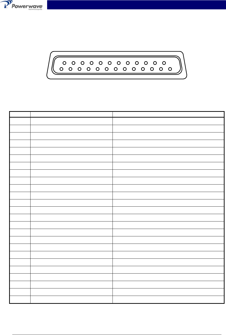
2-6 Data I/O Connector
The alarms and sensing connections on the amplifier are made through a 14-pin micro-fit con-
nector (figure 2-3) and are listed and described in table 2-2.
13
14
1
25
Figure 2-3 Data I/O Connector
Table 2-2 Data I/O Connector Definition
Pin Signal Description
1 Manuel control Control ON/OFF
2 GND Ground
3 PA-Enable-Actif + Control
4 PA-Enable-Actif - Control
5 PA_presence_reset Towards µcontroller
6 GND_presence_reset Ground
7 Reserved Reserved
8 GND Ground
9 Reserved Reserved
10 Reserved Reserved
11 GND Ground
12 Reserved Reserved
13 Reserved Reserved
14 UART TX+ (TRM to MCPA) Base Station Control and Alarm Signaling
15 UART TX- (TRM to MCPA) Base Station Control and Alarm Signaling
16 Reserved Reserved
17 UART RX+ (MCPA to TRM) Base Station Control and Alarm Signaling
18 UART RX- (MCPA to TRM) Base Station Control and Alarm Signaling
19 GND Ground
20 Reserved Reserved
21 Reserved Reserved
22 Reserved Reserved
23 Reserved Reserved
24 Reserved Reserved
25 Reserved Reserved
Copyright Powerwave Technologies, Inc., June 2003. All rights reserved
044-05141 Rev. A 2-3 June 2003

NTUM30DA Installation & Service Manual
Section 3 Operating Instructions
3-1 Introduction
This section contains operating instructions for the Multicarrier Cellular Amplifier.
3-2 Initial Start-Up & Operating Procedures
There are no operating controls or indicators on the NTUM30DA amplifier module. To perform
the initial start-up, proceed as follows:
1. Verify that all input and output cables are properly connected, per section 2.
CAUTION
Before applying power, make sure that the input and output of the amplifier are prop-
erly terminated at 50 ohms. Do not operate the amplifier without a load attached. Re-
fer to table 1-1 for input power requirements. Excessive input power may damage the
amplifier.
NOTE
The output coaxial cable between the amplifier and the antenna must be 50 ohm co-
axial cable. Use of any other cable will distort the output.
2. Turn on supply that provides -48 Vdc to the amplifier system.
3. Turn the amplifier front panel switch to On. The amplifier will run through built-in-test for a
few seconds, and notify the BTS when the loops converge. The base station allows up to 30
seconds for this step to complete.
4. Turn on external exciter/transceiver and apply RF input signals.
Copyright Powerwave Technologies, Inc., June 2003. All rights reserved
044-05141 Rev. A 3-1 June 2003

NTUM30DA Installation & Service Manual
Section 4 Principles of Operation
4-1 Introduction
This section contains a functional description of the multichannel power amplifier (MCPA).
4-2 RF Input Signal
The maximum input power should not exceed the limits specified in table 1-1.
4-3 RF Output Load
The load impedance should be as good as possible (1.5:1 or better) in the working band for good
power transfer to the load.
4-4 Amplifier Functional Description
The NTUM30DA amplifier (figures 1-1 and 4-1) is a linear, MCPA that operates in the 60 MHz
frequency band from 1930 MHz to 1990 MHz with an instantaneous bandwidth of 20 MHz. The
operating band is determined by the operating frequency selection(s) of the base station (refer to
table 1-1). The amplifier produces 45 watts of output power when operated in mode 1 or 30 watts
of output power when operated in mode 2. Each amplifier is a self-contained module and is func-
tionally independent of any other amplifier module(s) in the system. Each amplifier module has
an alarm board that monitors the amplifier performance. If a failure or fault occurs in an amplifier
module, it is transmitted to the host system via an RS-485 interface.
The amplifier is compliant to the requirements of FCC rules with respect to spurious emissions
(see table 1-1). Constant gain is maintained by continuously comparing active paths with passive
references, and correcting for small variations through the RF feedback controls. All gain varia-
tions, for example those due to temperature, are reduced to the passive reference variations.
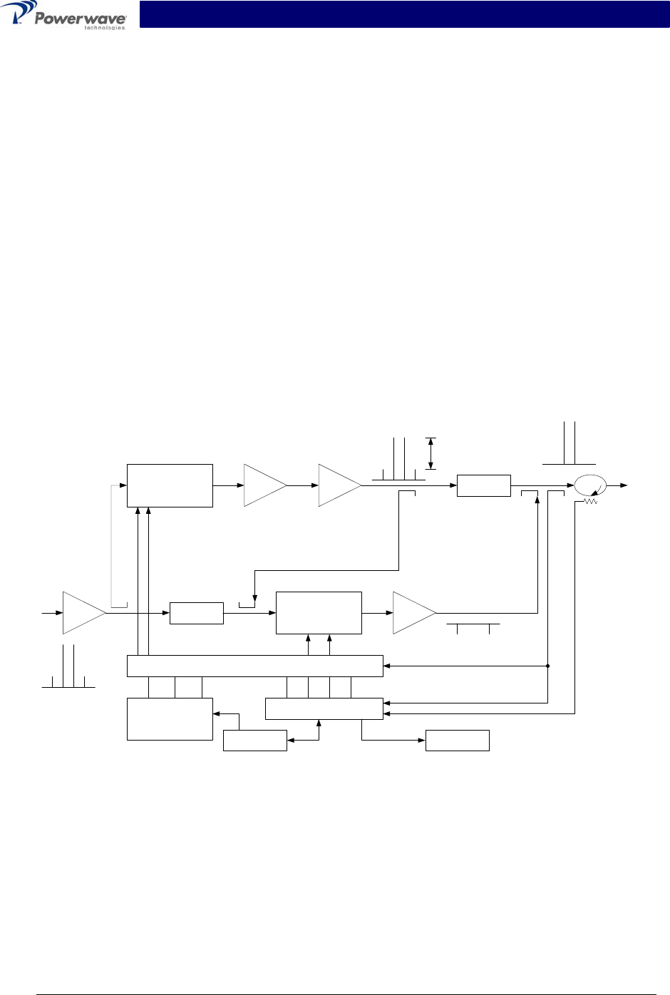
The amplifier module is comprised of:
An input amplifier
1st Loop Phase & Gain
A driver amplifier
A main amplifier
A multifunction board
4-4.1 Input Amplifier
RF is fed to the input amplifier, which consists of an isolator at the input, bandpass filter, voltage
variable attenuators (VVA), and phase shifters for gain control and phase sweeping functions.
The circuits in this section of the amplifier are controlled by a microprocessor on the Multifunction
board. At its output, the input amplifier splits the signal to the 1st Loop Phase and Gain circuit, and
the carrier cancellation circuit.
4-4.2 1st Loop Phase & Gain
The 1st Loop Phase & Gain circuit is a predistortion amplifier. The input signal is predistorted
such that it linearizes the output of the main amp at the rated output power of the MCPA. It also
contains the main loop VVAs and phase shifters. All the predistortion voltages and loop voltages
are controlled by a microprocessor.
Copyright Powerwave Technologies, Inc., June 2003. All rights reserved
044-05141 Rev. A 4-1 June 2003
NTUM30DA Installation & Service Manual
4-4.3 Driver Amplifier
The driver amplifier consists of two stages of class AB amplification, which provide the approxi-
mately 40% of the gain in the 60 MHz frequency band from 1930 MHz to 1990 MHz.
4-4.4 Main Amplifier
The main amplifier employs two class AB amplification stages for maximum efficiency. It provides
approximately 40% of the gain in the 60 MHz frequency band. The output from the main amplifier
is typically higher than the rated output power of the MCPA, to allow for losses associated with
the components in the remaining RF path. The RF signals are then applied to a delay line and
directional coupler, where the distortion products are cancelled out and the amplifier power per-
formance is monitored.
4-4.5 Multifunction Board
The multifunction board consists of feed forward loop control and alarm circuits. The MCPA com-
municates to the host system through the multifunction board, which gathers the status informa-
tion of the amplifier and reports to the host system via the RS-485 interface when instructed. It
also protects the MCPA from adverse conditions such as overpower, input overdrive, over-
voltage, etc. A microprocessor on the multifunction board also controls two loops in the feed-
forward system.
Pre
Amp
Driver Main
Amp
Error
Amp
Delay
Feed Forward Loop control
2nd Loop
Phase & Gain
1st Loop
Phase & Gain Delay
Alarms & Display
+15 +5 -5
Power Supply
-30dB -10dB
-40dB
RF Out
RFL
PWR
FWD
PWR
Front Panel
Smart Rack
+27VDC
Figure 4-1 NTUM30DA Multichannel Power Amplifier Functional Block Diagram
4-5 Amplifier Module Cooling
Each amplifier module is contained within a thermally conductive chassis and properly mounted
on an adequate thermal surface, which provides sufficient cooling when forced air is circulated
over the heat sink fins to maintain the amplifier within the specified operating temperature range.
Copyright Powerwave Technologies, Inc., June 2003. All rights reserved
044-05141 Rev. A 4-2 June 2003

NTUM30DA Installation & Service Manual
4-6 Power Distribution
Primary DC power for the amplifier is provided by the host system. The amplifier generates all
the required voltages internally from the main source.
4-7 Amplifier Alarms
4-7.1 Minor Alarms
When a minor alarm condition occurs, the alarm is latched into a minor alarm condition. The am-
plifier alarm state is read by the BTS the next time the amplifier is poled by the BTS. After the
alarm status is sent the minor alarm register is cleared, unless the alarm condition still exists. If
the amplifier receives a “Enable Command” or “Clear Alarms Command”, all minor alarms will be
cleared. If the amplifier is disabled, all minor alarms are also cleared.
Minor alarms do not directly affect amplifier functionality.
BTS MCPA
OPERATIONAL
Read Power and Status response - Alarm reported
Minor Alarm condition
appears
Minor Alarm condition
disappears
Read Power and Status command
Minor Alarm condition
still exists
Read Power and Status command
Read Power and Status response - Alarm reported
Read Power and Status command
Read Power and Status response - No Alarm reported
Figure 4-2 Minor Alarm Reporting Sequence
4-7.1.1 Main Loop Cancellation Alarm (1st Loop Alarm)
During normal operation, if the 1st Loop is not locked for 30 seconds a Main Loop Cancellation
Alarm is declared. During power-up, the BTS waits for 30 seconds to allow the 1st Loop to lock.
When the main amplifier is first turned on, the Main Loop Cancellation Alarm ON is on until the
loops converge. The BTS allows 30 seconds for the alarm to clear after putting the amplifier into
Operational mode before reporting the alarm.
Copyright Powerwave Technologies, Inc., June 2003. All rights reserved
044-05141 Rev. A 4-3 June 2003

NTUM30DA Installation & Service Manual
4-7.1.2 Error Loop Cancellation Alarm (2nd Loop Alarm)
During normal operation, if the 2nd Loop is not locked for 30 seconds a Error Loop Cancellation
Alarm is declared. During power-up, the BTS waits for 30 seconds to allow the 2nd Loop to lock.
When the error amplifier is first turned on, the Error Loop Cancellation Alarm ON status is on until
the loops converge. The BTS allows 30 seconds for the alarm to clear after putting the amplifier
into Operational mode before reporting the alarm.
Detected loss of pilot signal with the error amplifier on, also leads to an Error Loop Cancellation
Alarm.
4-7.1.3 Gain Alarm
The gain alarm is caused by either of the following conditions:
• No output power with a nominal input power.
(Pin > -3.8 dBm and Pout < 25 dBm for five seconds.
• Pin > +2.5 dB for five seconds.
4-7.1.4 Partial Failure of Main Amplifier Alarm (Transistor/Device Fail)
A sensor detects a main or error amplifier transistor failure. A transistor failure is detected as fol-
lows:
• When the main and error amplifiers are first turned on and converged, the Main VVA and Er-
ror VVA convergence points are compared to the Default Main VVA and Default Error VVA
values (with temperature compensation). If either of the VVAs is significantly lower than its
default value, the Partial Failure of Main Amplifier alarm is set.
• After the above test is performed, the Main VVA and Error VVA are continually monitored. If
the Main VVA or Error VVA significantly drop then the Partial Failure of Main Amplifier alarm
is set.
4-7.1.5 Over Temperature Warning Alarm
The MCPA will alarm if the temperature exceeds the normal operation temperature threshold
(90ºC internal temperature sensor) for five seconds. This threshold is a few degrees below the
Over Temperature Shutdown Alarm.
4-7.1.6 Power Supply Warning Alarm
The MCPA monitors the non-converter voltages, 15V, 5V and -5V power supply voltages and
alarms when of any of these DC voltages fail for at least five seconds. The normal operating
range for these voltages is: 15V + 1.5V, 5V + 0.5V and –5V + 0.5.
4-7.1.7 High DC Power Consumption Warning Alarm
If input DC power exceeds 375W in Mode 1 or 300W in Mode 2, for five seconds, the High DC
Power Consumption Warning Alarm is set.
Copyright Powerwave Technologies, Inc., June 2003. All rights reserved
044-05141 Rev. A 4-4 June 2003

NTUM30DA Installation & Service Manual
4-7.2 Major Alarms
When a major alarm condition occurs, the alarm is latched into a major alarm condition. The am-
plifier alarm state is read by the BTS the next time the amplifier is poled by the BTS. After the
alarm status is sent the major alarm register is not cleared. If the amplifier receives a “Enable
Command” or “Clear Alarms Command”, all major alarms will be cleared. If the amplifier is dis-
abled, all major alarms are also cleared.
Major alarms cause the amplifier to enter a STANDBY state, and the transceiver(s) associated
with the amplifier will be off-the-air. The error amplifier and main amplifier are turned off.
BTS MCPA
OPERATIONAL
Read Power and Status response - Alarm reported
Major Alarm condition
appears
Major Alarm condition
disappears
Read Power and Status command
Major Alarm condition
still exists
Read Power and Status command
Read Power and Status response - Alarm reported
Read Power and Status command
Read Power and Status response - Alarm reported
STANDBY
Figure 4-3 Major Alarm Reporting Sequence
4-7.2.1 Over Temperature Shutdown Alarm
The MCPA will alarm if the base plate temperature exceeds the temperature threshold at which
the MCPA can be damaged (95ºC) for five seconds. This condition does not auto-recover and will
require a reset command when the condition is corrected and the amplifier module has cooled
sufficiently.
4-7.2.2 Power Supply Shutdown Alarm
The MCPA monitors the converter power supply output voltages, 28V (23V in Mode 2) and 9V,
and sets the Power Supply Shutdown Alarm if a power supply converter fails for five seconds or
longer. The alarm is set under the following conditions and does not auto-recover:
• 28V > 30.8V or 28V < 24.8V in Mode 1 or 24V > 25.75V or 24V < 20.25V in Mode 2.
• 9V > 9.9V or 9V < 8.1V
Copyright Powerwave Technologies, Inc., June 2003. All rights reserved
044-05141 Rev. A 4-5 June 2003

NTUM30DA Installation & Service Manual
4-7.2.3 High DC Power Consumption Shutdown Alarm
If input power exceeds 417W in Mode 1 or 330W in Mode 2, for one second, the High DC Power
Consumption Shutdown Alarm is set.
Table 4-1 Alarm Summary
Alarm Definition Implementation Persistence
Time
Temperature Overload (Major) Temp Sensor Temperature > 90ºC 5 seconds
High Temperature (Minor) Temp Sensor Temperature > 85ºC 5 seconds
DC/DC Converter Shutdown
(Major)
9V or 28V (23V in Mode 2) more than 10%
out of tolerance
5 seconds
DC Voltage Regulation Failure
(Minor)
5V, -5V, +15V more than 10% out of toler-
ance
5 seconds
DC Power Consumption
Overload (Major)
Mode 1: Input DC power > 417W
Mode 2: Input DC power > 330W
1 second
High DC Power Consumption
(Minor)
Mode 1: Input DC power > 375W
Mode 2: Input DC power > 300W
5 seconds
Gain Control (Minor) 1. Input Power > +2.5 dB OR
2. Input Power > -3.8 dB AND Output
Power < 25 dBm
5 seconds (both)
Partial Failure of Main Ampli-
fier (Minor)
Main Amp or Error Amp transistor failure
detected.
---
Main Cancellation Loop (Mi-
nor)
1st Loop Error > 2.5V (No persistence
when amplifier first enabled.)
30 seconds
Error Cancellation Loop
(Minor)
2nd Loop Error > 2000 (No persistence
when amplifier first enabled.)
Loss of Pilot detected.
30 seconds
(on item 1)
Copyright Powerwave Technologies, Inc., June 2003. All rights reserved
044-05141 Rev. A 4-6 June 2003

NTUM30DA Installation & Service Manual
Section 5 Maintenance
5-1 Introduction
This section contains periodic maintenance and performance test procedures for the multichan-
nel power amplifier. It also contains a list of test equipment required to perform the identified
tasks.
NOTE
Check your sales order and equipment warranty before attempting to service or re-
pair the unit. Do not break the seals on equipment under warranty or the warranty
will be null and void. Do not return equipment for warranty or repair service until
proper shipping instructions are received from the factory.
5-2 Periodic Maintenance
Periodic maintenance requirements are listed in table 5-1. Table 5-1 also lists the intervals at
which the tasks should be performed.
Table 5-1 Periodic Maintenance
Task Interval Action
Inspection
Cables & Connectors 12 Months Inspect signal and power cables for frayed insulation.
Check RF connectors to be sure that they are tight.
Performance Tests No periodic maintenance is necessary beyond that
recommended by the base station manufacturer.
5-3 Field Replacement Of The Module
The NTUM30DA multichannel power amplifier module can be replaced in the field on site by a
qualified technician with adequate ESD protection and experience maintaining RF power amplifi-
ers and similar equipment.
To replace a power amplifier module, proceed as follows:
1. Turn off that specific module.
2. Disconnect the three RF cables and D-sub connectors (Power In and Data I/O).
3. Loosen 4 front panel captive screws that secure amplifier module to the base station.
4. Carefully remove amplifier module from the base station.
5. Install replacement in reverse order of steps 1 through 4 above.
Copyright Powerwave Technologies, Inc., June 2003. All rights reserved
044-05141 Rev. A 5-1 June 2003

NTUM30DA Installation & Service Manual
Section 6 Troubleshooting
6-1 Introduction
This section contains a list of problems and a few suggested actions that may correct the prob-
lem. If the suggested corrective action does not eliminate the problem, please contact your
Powerwave field representative or the factory for further instructions.
NOTE
Check your sales order and equipment warranty before attempting to service or re-
pair the unit. Do not break the seals on equipment under warranty or the warranty
will be null and void. Do not return equipment for warranty or repair service until
proper shipping instructions are received from the factory.
6-2 Troubleshooting
Refer to table 6-1 for troubleshooting suggestions.
Table 6-1 Troubleshooting
Symptom Suggested Action
MCPA Inoperative Check for proper power supply voltage.
MCPA Not Enabled Verify HPA-Allow-Enable line is high.
Alarm Output is (RS 422) High Verify input RF is within specified power and frequency limits
6-3 Return For Service Procedures
When returning products to Powerwave, the following procedures will ensure optimum response.
6-3.1 Obtaining An RMA
A Return Material Authorization (RMA) number must be obtained prior to returning equipment to
the factory for service. Please contact our Repair Department at (888) 797-9283 or (714) 466-
1000 to obtain this number, or FAX your request to (714) 466-5816. Failure to obtain this RMA
number may result in delays in receiving repair service.
6-3.2 Repackaging For Shipment
To ensure safe shipment of the amplifier, it is recommended that the package designed for the
amplifier be used. The original packaging material is reusable. If it is not available, contact
Powerwave’s Customer Service Department for packing materials and information.
Copyright Powerwave Technologies, Inc., June 2003. All rights reserved
044-05141 Rev. A 6-1 June 2003

NTUM30DA Installation & Service Manual
Field Failure Report
RMA No.: __________ S/N: __________ Customer: ___________________
Region: ________________ Technician: ___________________ Phone No.: __________
Manufacture Date: ___________ Failure Date: ___________ Site ID: _____________
Does customer want a Failure Analysis Report? Y / N
Failure Mode (please circle all that apply):
Loop Fail VSWR Low Pwr Ovr Pwr DC LPA Disable
Ovr Temp Alarm No RF Out Firmware Shipping Damage
Missing Hardware Connector Damaged
Failed During (please circle all that apply):
Installation Normal Operation Scheduled Maintenance
High Traffic Hour Medium Traffic Hour Low Traffic Hour
DOA? Y / N
Failure Frequency:
Intermittent Permanent
Failure Details:
Did other equipment fail at the same time? (Please describe)
Copyright Powerwave Technologies, Inc., June 2003. All rights reserved
044-05141 Rev. A 6-2 June 2003