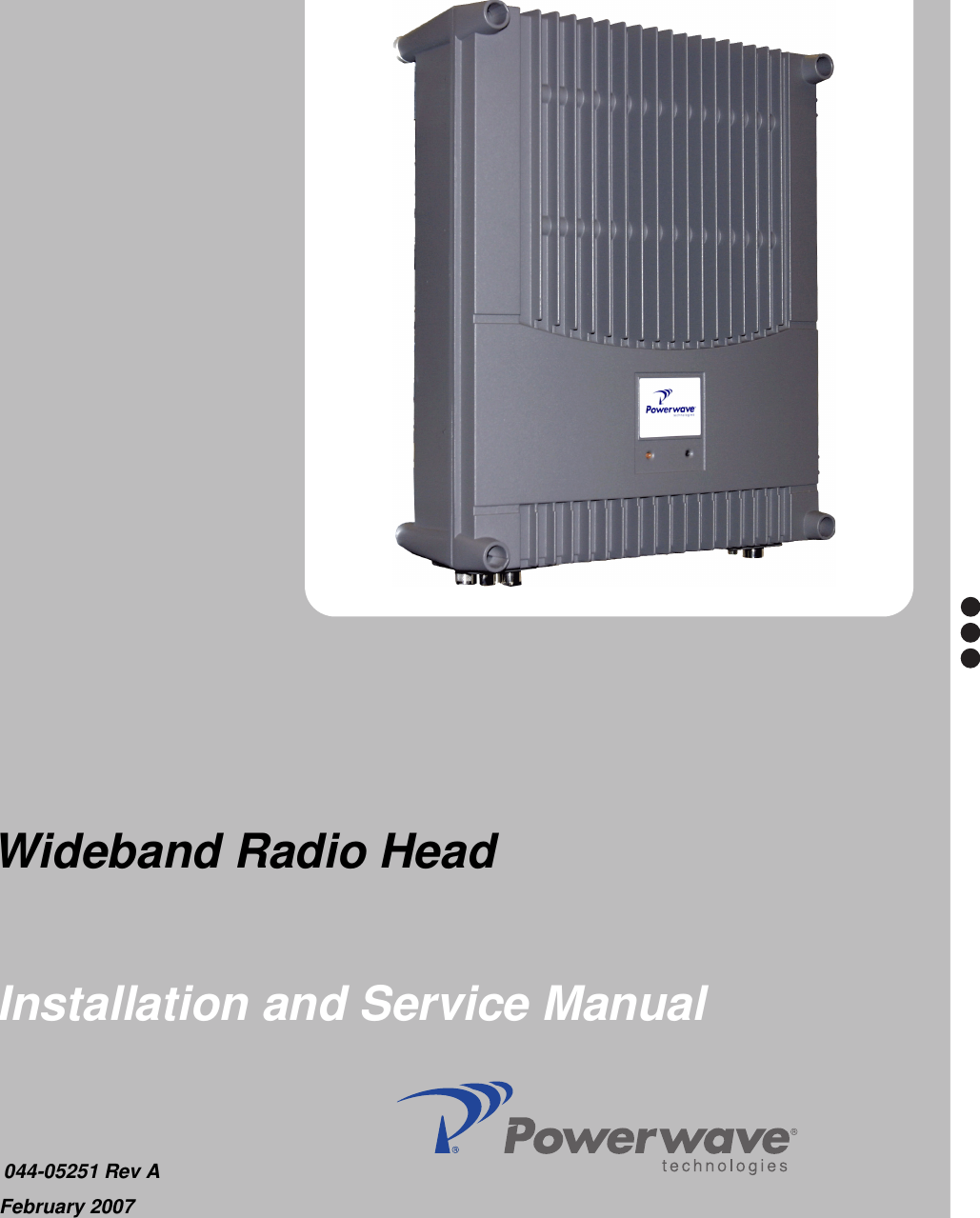
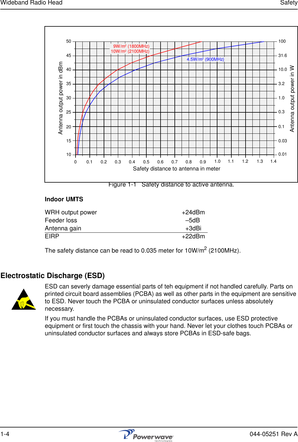
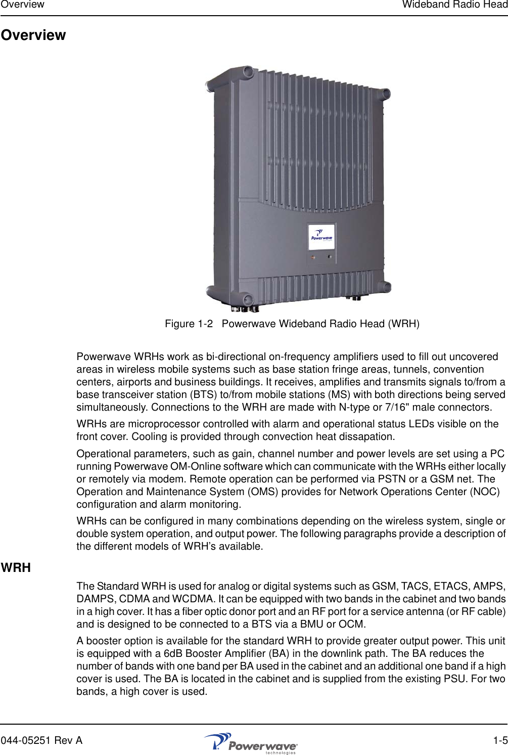
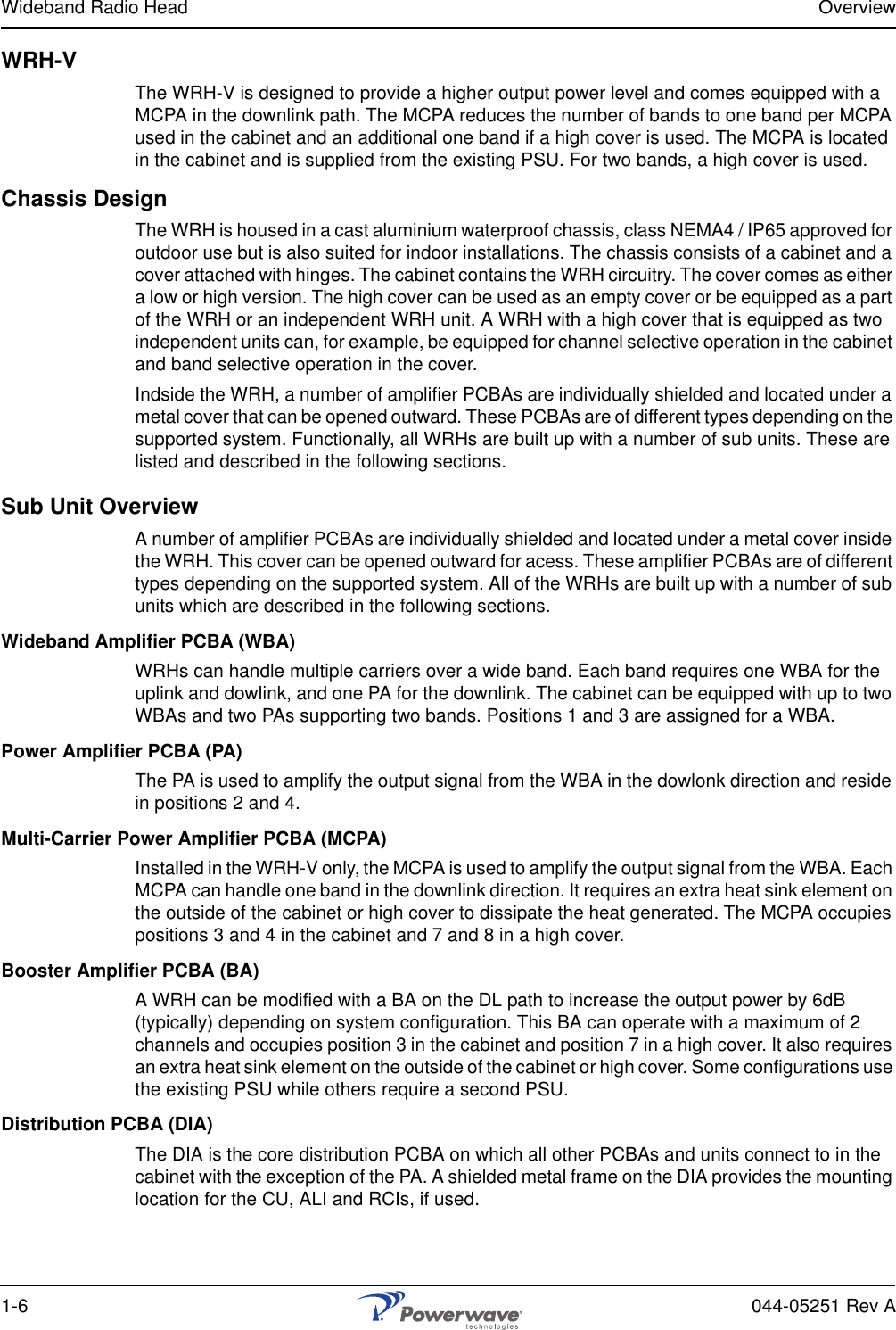
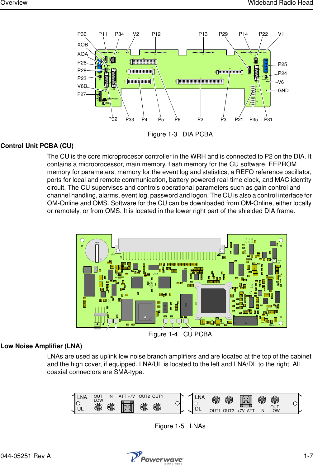
Powerwave Technologies 5JS0090 Wideband Radio Head (WRH) User Manual 044 05251 WRH

Powerwave Technologies Inc Wideband Radio Head (WRH) 044 05251 WRH

Users Manual

  Installation and Service Manual  044-05251 Rev AFebruary 2007  Wideband Radio Head
© 2007 Powerwave Technologies Incorporated. All rights reserved.Powerwave Technologies and the Powerwave logo are registered trademarks.Powerwave Technologies Inc. reserves the right to make changes to the documentation and equipment, includ-ing but not limited to component substitution and circuitry changes. Changes that impact this document may subsequently be incorporated in a later revision of this document.This Powerwave product is designed to operate within the Normal Operating (typical operating) ranges or con-ditions specified in this document. Operation of this equipment beyond the specified ranges in this document may cause (1) spurious emissions that violate regulatory requirements; (2) the equipment to be automatically removed from service when maximum thresholds are exceeded; or (3) the equipment to not perform in accor-dance with its specifications. It is the Operator's responsibility to ensure this equipment is properly installed and operated within Powerwave operating specifications to obtain proper performance from the equipment and to comply with regulatory requirements.The rated output power of this equipment is for single carrier operation. For situations when multiple carrier sig-nals are present, the rating would have to be reduced by 3.5 dB, especially where the output signal is re-radi-ated and can cause interference to adjacent band users. This power reduction is to be by means of input power or gain reduction and not by an attenuator at the output of the device. Input power is rated at 115/230VAC, 50/60Hz, and should be protected with a 20 A breaker. Power strips should, at a minimum, conform to this require-ment to prevent equipment damage and possible overload.Federal Communications Commission (FCC)This equipment has been tested and found to comply with the limits for a Class A digital device, pursuant to part 15 of the FCC Rules. Changes or modifications not expressly approved by Powerwave Technologies, Inc. for compliance could void the user’s authority to operate this equipment. These limits are designed to provide reasonable protection against harmful interference when the equipment is operated in a commercial environ-ment. This equipment generates, uses, and can radiate radio frequency energy and, if not installed and used in accordance with the instruction manual, may cause harmful interference to radio communications. Operation of this equipment in a residential area is likely to cause harmful interference in which case the user will be required to correct the interference at his own expense.Industry Canadian RequirementAll Powerwave apparatus introduced on the Canadian market meet all requirements of the Canadian Interfer-ence-Causing Equipment Regulations. The -20dB bandwidth is 80MHz.Powerwave Technologies Inc., 1801 East St. Andrew Place, CA 92705 Santa Ana, USA.Phone +1 714 466 1000 – Fax +1 714 466 5800 – Internet www.powerwave.com
Wideband Radio Head Revision Record044-05251 Rev A iRevision Record Revision Letter  Date of Change Reason for Change3A August 2005 Original VD203 66A December 2006 Document number changed to 044-05251 and manual updated
ii 044-05251 Rev AThis Page Intentionally Left Blank
044-05251 Rev A iTable of ContentsAbbreviations  . . . . . . . . . . . . . . . . . . . . . . . . . . . . . . . . . . . . . . . . . . . . . . . . . . . . . . . . . . . . . . . . . . . . . . .  vChapter 1 - Product DescriptionIntroduction . . . . . . . . . . . . . . . . . . . . . . . . . . . . . . . . . . . . . . . . . . . . . . . . . . . . . . . . . . . . . . . . . . . . . . . .1-1Scope of Manual . . . . . . . . . . . . . . . . . . . . . . . . . . . . . . . . . . . . . . . . . . . . . . . . . . . . . . . . . . . . . . . . . . . .1-1Safety  . . . . . . . . . . . . . . . . . . . . . . . . . . . . . . . . . . . . . . . . . . . . . . . . . . . . . . . . . . . . . . . . . . . . . . . . . . . .1-1Warning Signs  . . . . . . . . . . . . . . . . . . . . . . . . . . . . . . . . . . . . . . . . . . . . . . . . . . . . . . . . . . . . . . . . . .1-2Human Exposure of RF Radiation  . . . . . . . . . . . . . . . . . . . . . . . . . . . . . . . . . . . . . . . . . . . . . . . . . . .1-2Antennas  . . . . . . . . . . . . . . . . . . . . . . . . . . . . . . . . . . . . . . . . . . . . . . . . . . . . . . . . . . . . . . . . . . .1-2Installation and Maintenance of Antenna Systems. . . . . . . . . . . . . . . . . . . . . . . . . . . . . . . . . . . .1-2Radiation Exposure  . . . . . . . . . . . . . . . . . . . . . . . . . . . . . . . . . . . . . . . . . . . . . . . . . . . . . . . . . . .1-2Radiation Safety Distances  . . . . . . . . . . . . . . . . . . . . . . . . . . . . . . . . . . . . . . . . . . . . . . . . . . . . . . . .1-3Electrostatic Discharge (ESD)  . . . . . . . . . . . . . . . . . . . . . . . . . . . . . . . . . . . . . . . . . . . . . . . . . . . . . .1-4Overview . . . . . . . . . . . . . . . . . . . . . . . . . . . . . . . . . . . . . . . . . . . . . . . . . . . . . . . . . . . . . . . . . . . . . . . . . .1-5WRH . . . . . . . . . . . . . . . . . . . . . . . . . . . . . . . . . . . . . . . . . . . . . . . . . . . . . . . . . . . . . . . . . . . . . . . . . .1-5WRH-V . . . . . . . . . . . . . . . . . . . . . . . . . . . . . . . . . . . . . . . . . . . . . . . . . . . . . . . . . . . . . . . . . . . . . . . .1-6Chassis Design . . . . . . . . . . . . . . . . . . . . . . . . . . . . . . . . . . . . . . . . . . . . . . . . . . . . . . . . . . . . . . . . . .1-6Sub Unit Overview  . . . . . . . . . . . . . . . . . . . . . . . . . . . . . . . . . . . . . . . . . . . . . . . . . . . . . . . . . . . . . . .1-6Wideband Amplifier PCBA (WBA)  . . . . . . . . . . . . . . . . . . . . . . . . . . . . . . . . . . . . . . . . . . . . . . . .1-6Power Amplifier PCBA (PA) . . . . . . . . . . . . . . . . . . . . . . . . . . . . . . . . . . . . . . . . . . . . . . . . . . . . .1-6Multi-Carrier Power Amplifier PCBA (MCPA). . . . . . . . . . . . . . . . . . . . . . . . . . . . . . . . . . . . . . . .1-6Booster Amplifier PCBA (BA) . . . . . . . . . . . . . . . . . . . . . . . . . . . . . . . . . . . . . . . . . . . . . . . . . . . .1-6Distribution PCBA (DIA) . . . . . . . . . . . . . . . . . . . . . . . . . . . . . . . . . . . . . . . . . . . . . . . . . . . . . . . .1-6Control Unit PCBA (CU) . . . . . . . . . . . . . . . . . . . . . . . . . . . . . . . . . . . . . . . . . . . . . . . . . . . . . . . .1-7Low Noise Amplifier (LNA) . . . . . . . . . . . . . . . . . . . . . . . . . . . . . . . . . . . . . . . . . . . . . . . . . . . . . .1-7Duplex Filter (DPX). . . . . . . . . . . . . . . . . . . . . . . . . . . . . . . . . . . . . . . . . . . . . . . . . . . . . . . . . . . .1-8Fiber Optic Unit (FOU) . . . . . . . . . . . . . . . . . . . . . . . . . . . . . . . . . . . . . . . . . . . . . . . . . . . . . . . . .1-8Fiber Optic Node (FON) . . . . . . . . . . . . . . . . . . . . . . . . . . . . . . . . . . . . . . . . . . . . . . . . . . . . . . . .1-8Power Supply Unit (PSU) . . . . . . . . . . . . . . . . . . . . . . . . . . . . . . . . . . . . . . . . . . . . . . . . . . . . . . .1-8Remote Control Unit (RCU) . . . . . . . . . . . . . . . . . . . . . . . . . . . . . . . . . . . . . . . . . . . . . . . . . . . . .1-8Alarm Interface PCBA (ALI) and Remote Control Interface PCBA (RCI) . . . . . . . . . . . . . . . . . . .1-9Sub Unit Locations . . . . . . . . . . . . . . . . . . . . . . . . . . . . . . . . . . . . . . . . . . . . . . . . . . . . . . . . . . . . . . .1-9WRH. . . . . . . . . . . . . . . . . . . . . . . . . . . . . . . . . . . . . . . . . . . . . . . . . . . . . . . . . . . . . . . . . . . . . . .1-9WRH-V . . . . . . . . . . . . . . . . . . . . . . . . . . . . . . . . . . . . . . . . . . . . . . . . . . . . . . . . . . . . . . . . . . . .1-10Fiber Optic Distribution Networks . . . . . . . . . . . . . . . . . . . . . . . . . . . . . . . . . . . . . . . . . . . . . . . . . . .1-11Multi-Operator Configurations  . . . . . . . . . . . . . . . . . . . . . . . . . . . . . . . . . . . . . . . . . . . . . . . . . . . . .1-11Chapter 2 - Controls, Indicators and ConnectorsIntroduction . . . . . . . . . . . . . . . . . . . . . . . . . . . . . . . . . . . . . . . . . . . . . . . . . . . . . . . . . . . . . . . . . . . . . . . .2-1Front Cover Indicators. . . . . . . . . . . . . . . . . . . . . . . . . . . . . . . . . . . . . . . . . . . . . . . . . . . . . . . . . . . . . . . .2-1Cabinet Indicators . . . . . . . . . . . . . . . . . . . . . . . . . . . . . . . . . . . . . . . . . . . . . . . . . . . . . . . . . . . . . . . . . . .2-1PCBA Indicators  . . . . . . . . . . . . . . . . . . . . . . . . . . . . . . . . . . . . . . . . . . . . . . . . . . . . . . . . . . . . . . . . . . . .2-2CU PCBA  . . . . . . . . . . . . . . . . . . . . . . . . . . . . . . . . . . . . . . . . . . . . . . . . . . . . . . . . . . . . . . . . . . . . . .2-2FON PCBA . . . . . . . . . . . . . . . . . . . . . . . . . . . . . . . . . . . . . . . . . . . . . . . . . . . . . . . . . . . . . . . . . . . . .2-3PCBA Connectors . . . . . . . . . . . . . . . . . . . . . . . . . . . . . . . . . . . . . . . . . . . . . . . . . . . . . . . . . . . . . . . . . . .2-4BA PCBA  . . . . . . . . . . . . . . . . . . . . . . . . . . . . . . . . . . . . . . . . . . . . . . . . . . . . . . . . . . . . . . . . . . . . . .2-5DIA PCBA   . . . . . . . . . . . . . . . . . . . . . . . . . . . . . . . . . . . . . . . . . . . . . . . . . . . . . . . . . . . . . . . . . . . . .2-5DPX  . . . . . . . . . . . . . . . . . . . . . . . . . . . . . . . . . . . . . . . . . . . . . . . . . . . . . . . . . . . . . . . . . . . . . . . . . .2-6LNA   . . . . . . . . . . . . . . . . . . . . . . . . . . . . . . . . . . . . . . . . . . . . . . . . . . . . . . . . . . . . . . . . . . . . . . . . . .2-6FOU – Fiber Optic Unit . . . . . . . . . . . . . . . . . . . . . . . . . . . . . . . . . . . . . . . . . . . . . . . . . . . . . . . . . . . .2-7FON  . . . . . . . . . . . . . . . . . . . . . . . . . . . . . . . . . . . . . . . . . . . . . . . . . . . . . . . . . . . . . . . . . . . . . . . . . .2-7
Wideband Radio Head Wideband Radio Headii 044-05251 Rev APSU  . . . . . . . . . . . . . . . . . . . . . . . . . . . . . . . . . . . . . . . . . . . . . . . . . . . . . . . . . . . . . . . . . . . . . . . . . .2-9Software and Hardware Compatibility . . . . . . . . . . . . . . . . . . . . . . . . . . . . . . . . . . . . . . . . . . . . . . . . . . .2-10Chapter 3 - InstallationIntroduction . . . . . . . . . . . . . . . . . . . . . . . . . . . . . . . . . . . . . . . . . . . . . . . . . . . . . . . . . . . . . . . . . . . . . . . .3-1Site Survey  . . . . . . . . . . . . . . . . . . . . . . . . . . . . . . . . . . . . . . . . . . . . . . . . . . . . . . . . . . . . . . . . . . . . . . . .3-1Unpacking and Inspection . . . . . . . . . . . . . . . . . . . . . . . . . . . . . . . . . . . . . . . . . . . . . . . . . . . . . . . . . . . . .3-1WRH Location . . . . . . . . . . . . . . . . . . . . . . . . . . . . . . . . . . . . . . . . . . . . . . . . . . . . . . . . . . . . . . . . . . . . . .3-1Mounting . . . . . . . . . . . . . . . . . . . . . . . . . . . . . . . . . . . . . . . . . . . . . . . . . . . . . . . . . . . . . . . . . . . . . . . . . .3-1Connections. . . . . . . . . . . . . . . . . . . . . . . . . . . . . . . . . . . . . . . . . . . . . . . . . . . . . . . . . . . . . . . . . . . . . . . .3-4Main Power and Grounding  . . . . . . . . . . . . . . . . . . . . . . . . . . . . . . . . . . . . . . . . . . . . . . . . . . . . . . . .3-4Fiber Optic and RF Connections. . . . . . . . . . . . . . . . . . . . . . . . . . . . . . . . . . . . . . . . . . . . . . . . . . . . .3-5WRH . . . . . . . . . . . . . . . . . . . . . . . . . . . . . . . . . . . . . . . . . . . . . . . . . . . . . . . . . . . . . . . . . . . . . . .3-5WRH-V . . . . . . . . . . . . . . . . . . . . . . . . . . . . . . . . . . . . . . . . . . . . . . . . . . . . . . . . . . . . . . . . . . . . .3-6Optional Connections  . . . . . . . . . . . . . . . . . . . . . . . . . . . . . . . . . . . . . . . . . . . . . . . . . . . . . . . . . . . . . . . .3-6Alarms. . . . . . . . . . . . . . . . . . . . . . . . . . . . . . . . . . . . . . . . . . . . . . . . . . . . . . . . . . . . . . . . . . . . . . . . .3-6External Alarm. . . . . . . . . . . . . . . . . . . . . . . . . . . . . . . . . . . . . . . . . . . . . . . . . . . . . . . . . . . . . . . . . . .3-6Door Open Alarm  . . . . . . . . . . . . . . . . . . . . . . . . . . . . . . . . . . . . . . . . . . . . . . . . . . . . . . . . . . . . . . . .3-7Fiber Link Interface (FLI). . . . . . . . . . . . . . . . . . . . . . . . . . . . . . . . . . . . . . . . . . . . . . . . . . . . . . . . . . .3-7Wire Link Interface (WLI) Network (IP to R2R) . . . . . . . . . . . . . . . . . . . . . . . . . . . . . . . . . . . . . . . . . .3-7Main Power Breakdown Relay . . . . . . . . . . . . . . . . . . . . . . . . . . . . . . . . . . . . . . . . . . . . . . . . . . . . . .3-921-60 Volt DC PSU Installation . . . . . . . . . . . . . . . . . . . . . . . . . . . . . . . . . . . . . . . . . . . . . . . . . . . . .3-10Commissioning  . . . . . . . . . . . . . . . . . . . . . . . . . . . . . . . . . . . . . . . . . . . . . . . . . . . . . . . . . . . . . . . . . . . .3-11Initial Startup . . . . . . . . . . . . . . . . . . . . . . . . . . . . . . . . . . . . . . . . . . . . . . . . . . . . . . . . . . . . . . . . . . .3-11Chapter 4 - MaintenanceIntroduction . . . . . . . . . . . . . . . . . . . . . . . . . . . . . . . . . . . . . . . . . . . . . . . . . . . . . . . . . . . . . . . . . . . . . . . .4-1Periodic Maintenance  . . . . . . . . . . . . . . . . . . . . . . . . . . . . . . . . . . . . . . . . . . . . . . . . . . . . . . . . . . . . . . . .4-1Troubleshooting. . . . . . . . . . . . . . . . . . . . . . . . . . . . . . . . . . . . . . . . . . . . . . . . . . . . . . . . . . . . . . . . . . . . .4-1Clearing Alarm Faults . . . . . . . . . . . . . . . . . . . . . . . . . . . . . . . . . . . . . . . . . . . . . . . . . . . . . . . . . . . . .4-1Field Replaceable Units. . . . . . . . . . . . . . . . . . . . . . . . . . . . . . . . . . . . . . . . . . . . . . . . . . . . . . . . . . . . . . .4-9FON. . . . . . . . . . . . . . . . . . . . . . . . . . . . . . . . . . . . . . . . . . . . . . . . . . . . . . . . . . . . . . . . . . . . . . . . . . .4-9PSU. . . . . . . . . . . . . . . . . . . . . . . . . . . . . . . . . . . . . . . . . . . . . . . . . . . . . . . . . . . . . . . . . . . . . . . . . . .4-9WRH . . . . . . . . . . . . . . . . . . . . . . . . . . . . . . . . . . . . . . . . . . . . . . . . . . . . . . . . . . . . . . . . . . . . . . . . .4-10Return For Service Procedures . . . . . . . . . . . . . . . . . . . . . . . . . . . . . . . . . . . . . . . . . . . . . . . . . . . . . . . .4-10Obtaining an RMA. . . . . . . . . . . . . . . . . . . . . . . . . . . . . . . . . . . . . . . . . . . . . . . . . . . . . . . . . . . . . . .4-10Repackaging for Shipment . . . . . . . . . . . . . . . . . . . . . . . . . . . . . . . . . . . . . . . . . . . . . . . . . . . . . . . .4-10Remote Control Unit (RCU). . . . . . . . . . . . . . . . . . . . . . . . . . . . . . . . . . . . . . . . . . . . . . . . . . . . . . . . . . .4-10RCU for Radio Communication. . . . . . . . . . . . . . . . . . . . . . . . . . . . . . . . . . . . . . . . . . . . . . . . . . . . .4-11RCU for Telephone Line Communication . . . . . . . . . . . . . . . . . . . . . . . . . . . . . . . . . . . . . . . . . . . . .4-11Repeater-to-Repeater Link (R2R) . . . . . . . . . . . . . . . . . . . . . . . . . . . . . . . . . . . . . . . . . . . . . . . . . . . . . .4-11Chapter 5 - SpecificationsIntroduction . . . . . . . . . . . . . . . . . . . . . . . . . . . . . . . . . . . . . . . . . . . . . . . . . . . . . . . . . . . . . . . . . . . . . . . .5-1Appendix A - Block DiagramsIntroduction . . . . . . . . . . . . . . . . . . . . . . . . . . . . . . . . . . . . . . . . . . . . . . . . . . . . . . . . . . . . . . . . . . . . . . .  A-1Standard WRH  . . . . . . . . . . . . . . . . . . . . . . . . . . . . . . . . . . . . . . . . . . . . . . . . . . . . . . . . . . . . . . . . . . . .  A-1WRH-V  . . . . . . . . . . . . . . . . . . . . . . . . . . . . . . . . . . . . . . . . . . . . . . . . . . . . . . . . . . . . . . . . . . . . . . . . . .  A-2
Wideband Radio Head List of Figures044-05251 Rev A iiiList of Figures1-1 Safety Distance to Active Antenna  . . . . . . . . . . . . . . . . . . . . . . . . . . . . . . . . . . . . . . . . . . . . . . . . . .1-41-2 Powerwave Wideband Radio Head (WRH) . . . . . . . . . . . . . . . . . . . . . . . . . . . . . . . . . . . . . . . . . . . .1-51-3 Standard WRH Sub Unit Locations . . . . . . . . . . . . . . . . . . . . . . . . . . . . . . . . . . . . . . . . . . . . . . . . . .1-71-4 Standard WRH with Booster Option Sub Unit Locations   . . . . . . . . . . . . . . . . . . . . . . . . . . . . . . . . .1-81-5 WRH-V Sub Unit Locations . . . . . . . . . . . . . . . . . . . . . . . . . . . . . . . . . . . . . . . . . . . . . . . . . . . . . . . .1-81-6 Star Configuration Using One BMU and Four FORs . . . . . . . . . . . . . . . . . . . . . . . . . . . . . . . . . . . . .1-91-7 Daisy-chain Configuration Using One RMU and Four FORs. . . . . . . . . . . . . . . . . . . . . . . . . . . . . . .1-91-8 Multi-operator System . . . . . . . . . . . . . . . . . . . . . . . . . . . . . . . . . . . . . . . . . . . . . . . . . . . . . . . . . . .1-102-1 External Indicators  . . . . . . . . . . . . . . . . . . . . . . . . . . . . . . . . . . . . . . . . . . . . . . . . . . . . . . . . . . . . . .2-12-2 Cabinet Internal Indicators  . . . . . . . . . . . . . . . . . . . . . . . . . . . . . . . . . . . . . . . . . . . . . . . . . . . . . . . .2-12-3 DIA PCBA Connectors and Indicators   . . . . . . . . . . . . . . . . . . . . . . . . . . . . . . . . . . . . . . . . . . . . . . .2-32-4 CU PCBA Indicators  . . . . . . . . . . . . . . . . . . . . . . . . . . . . . . . . . . . . . . . . . . . . . . . . . . . . . . . . . . . . .2-42-5 Low Noise Amplifiers . . . . . . . . . . . . . . . . . . . . . . . . . . . . . . . . . . . . . . . . . . . . . . . . . . . . . . . . . . . . .2-52-6 Fiber Optic Unit (FOU). . . . . . . . . . . . . . . . . . . . . . . . . . . . . . . . . . . . . . . . . . . . . . . . . . . . . . . . . . . .2-62-7 3-port FON LED Indicators  . . . . . . . . . . . . . . . . . . . . . . . . . . . . . . . . . . . . . . . . . . . . . . . . . . . . . . . .2-82-8 4-port FON LED Indicators  . . . . . . . . . . . . . . . . . . . . . . . . . . . . . . . . . . . . . . . . . . . . . . . . . . . . . . . .2-82-9 Power Supply Unit (PSU)  . . . . . . . . . . . . . . . . . . . . . . . . . . . . . . . . . . . . . . . . . . . . . . . . . . . . . . . .2-103-1 Mounting Bracket. . . . . . . . . . . . . . . . . . . . . . . . . . . . . . . . . . . . . . . . . . . . . . . . . . . . . . . . . . . . . . . .3-13-2 Mounting Bracket Installation on Wall . . . . . . . . . . . . . . . . . . . . . . . . . . . . . . . . . . . . . . . . . . . . . . . .3-23-3 Attaching the Bracket to a Pole . . . . . . . . . . . . . . . . . . . . . . . . . . . . . . . . . . . . . . . . . . . . . . . . . . . . .3-23-4 Attaching the Bracket to a Mast. . . . . . . . . . . . . . . . . . . . . . . . . . . . . . . . . . . . . . . . . . . . . . . . . . . . .3-33-5 Attaching the WRH to the Bracket   . . . . . . . . . . . . . . . . . . . . . . . . . . . . . . . . . . . . . . . . . . . . . . . . . .3-33-6 RF-to-RF WRH Connections . . . . . . . . . . . . . . . . . . . . . . . . . . . . . . . . . . . . . . . . . . . . . . . . . . . . . . .3-53-7 External Alarm Connection  . . . . . . . . . . . . . . . . . . . . . . . . . . . . . . . . . . . . . . . . . . . . . . . . . . . . . . . .3-63-8 IP and R2R Network Connection. . . . . . . . . . . . . . . . . . . . . . . . . . . . . . . . . . . . . . . . . . . . . . . . . . . .3-73-9 Main Power Breakdown Relay Connection . . . . . . . . . . . . . . . . . . . . . . . . . . . . . . . . . . . . . . . . . . . .3-83-10 Replacing the PSU  . . . . . . . . . . . . . . . . . . . . . . . . . . . . . . . . . . . . . . . . . . . . . . . . . . . . . . . . . . . . . .3-93-11 Connecting a PC for Local Access  . . . . . . . . . . . . . . . . . . . . . . . . . . . . . . . . . . . . . . . . . . . . . . . . .3-104-1 RCU in the WRH Cabinet  . . . . . . . . . . . . . . . . . . . . . . . . . . . . . . . . . . . . . . . . . . . . . . . . . . . . . . . .4-114-2 R2R Network . . . . . . . . . . . . . . . . . . . . . . . . . . . . . . . . . . . . . . . . . . . . . . . . . . . . . . . . . . . . . . . . . .4-12List of Tables2-1 WBA PCBA Connectors  . . . . . . . . . . . . . . . . . . . . . . . . . . . . . . . . . . . . . . . . . . . . . . . . . . . . . . . . . .2-22-2 BA PCBA Connectors . . . . . . . . . . . . . . . . . . . . . . . . . . . . . . . . . . . . . . . . . . . . . . . . . . . . . . . . . . . .2-22-3 DIA PCBA Connectors. . . . . . . . . . . . . . . . . . . . . . . . . . . . . . . . . . . . . . . . . . . . . . . . . . . . . . . . . . . .2-32-4 CU PCBA LED Indicators  . . . . . . . . . . . . . . . . . . . . . . . . . . . . . . . . . . . . . . . . . . . . . . . . . . . . . . . . .2-42-5 Low Noise Amplifier Connections . . . . . . . . . . . . . . . . . . . . . . . . . . . . . . . . . . . . . . . . . . . . . . . . . . .2-52-6 DPX Connections  . . . . . . . . . . . . . . . . . . . . . . . . . . . . . . . . . . . . . . . . . . . . . . . . . . . . . . . . . . . . . . .2-62-7 FOU/DPX Connections . . . . . . . . . . . . . . . . . . . . . . . . . . . . . . . . . . . . . . . . . . . . . . . . . . . . . . . . . . .2-72-8 FON LED Indicators. . . . . . . . . . . . . . . . . . . . . . . . . . . . . . . . . . . . . . . . . . . . . . . . . . . . . . . . . . . . . .2-82-9 FON Connectors . . . . . . . . . . . . . . . . . . . . . . . . . . . . . . . . . . . . . . . . . . . . . . . . . . . . . . . . . . . . . . . .2-92-10 PSU Connectors  . . . . . . . . . . . . . . . . . . . . . . . . . . . . . . . . . . . . . . . . . . . . . . . . . . . . . . . . . . . . . . .2-102-11 Hardware/Software Compatibility  . . . . . . . . . . . . . . . . . . . . . . . . . . . . . . . . . . . . . . . . . . . . . . . . . .2-14 3-1 Cable Connection Procedure. . . . . . . . . . . . . . . . . . . . . . . . . . . . . . . . . . . . . . . . . . . . . . . . . . . . . . .3-53-2 Main Power Breakdown Relay Connection   . . . . . . . . . . . . . . . . . . . . . . . . . . . . . . . . . . . . . . . . . . .3-83-3 PSU Replacement Procedure . . . . . . . . . . . . . . . . . . . . . . . . . . . . . . . . . . . . . . . . . . . . . . . . . . . . . .3-9
Wideband Radio Head Wideband Radio Headiv 044-05251 Rev A3-4 Initial Startup Procedure  . . . . . . . . . . . . . . . . . . . . . . . . . . . . . . . . . . . . . . . . . . . . . . . . . . . . . . . . .3-104-1 Recommended Periodic Maintenance  . . . . . . . . . . . . . . . . . . . . . . . . . . . . . . . . . . . . . . . . . . . . . . .4-14-2 Alarm Troubleshooting  . . . . . . . . . . . . . . . . . . . . . . . . . . . . . . . . . . . . . . . . . . . . . . . . . . . . . . . . . . .4-14-3 FON Replacement Procedure   . . . . . . . . . . . . . . . . . . . . . . . . . . . . . . . . . . . . . . . . . . . . . . . . . . . . .4-94-4 PSU Replacement Procedure . . . . . . . . . . . . . . . . . . . . . . . . . . . . . . . . . . . . . . . . . . . . . . . . . . . . .4-104-5 WRH Replacement Procedure  . . . . . . . . . . . . . . . . . . . . . . . . . . . . . . . . . . . . . . . . . . . . . . . . . . . .4-105-1 AR Standard WRH Specifications   . . . . . . . . . . . . . . . . . . . . . . . . . . . . . . . . . . . . . . . . . . . . . . . . . .5-1
Wideband Radio Head Abbreviations044-05251 Rev A vAbbreviationsThe following list of abbreviations are used throughout this manual, the software, and the repeater:AGC Automatic Gain ControlALI Alarm InterfaceAMPS Advanced Mobile Phone ServiceBA Booster AmplifierBeO Beryllium OxideBMU Base Station Master UnitBS Base Station, BS antenna = towards the base stationBSA Band Selective AmplifierBSel Band SelectiveBTS Base Transceiver StationCDMA Code Division Multiple AccessCHE Channel Amplifier for GSM and EDGECMB CombinerCSA Channel Selective AmplifierCSel Channel SelectiveCU Control UnitCW Continuous WaveDAMPS Digital Advanced Mobile Phone ServiceDC Directional CouplerDCS Digital Communication System (same as PCN)DIA Distribution InterfaceDL Downlink signal direction (from base station via repeater to mobile station)DPX Duplex filterEDGE Enhanced Data rates for GSM EvolutionEEPROM Electrical Erasable Programmable Read Only MemoryEGSM Extended Global System for Mobile communicationESD Electrostatic DischargeETACS Extended Total Access Communication SystemETSI European Telecommunications Standard InstituteFLI Fiber Link InterfaceFON Fiber Optic NodeFOR Fiber Optic RepeaterFOU Fiber Optic UnitGSM Global System for Mobile communicationHW HardwareICNIRP International Commission on Non-Ionizing Radiation ProtectionLED Light Emitting DiodeLNA Low Noise AmplifierMS Mobile Station, MS antenna = towards the mobile stationMSC Mobile Switching CenterNEMA National Electrical Manufacturers Association
Wideband Radio Head Wideband Radio Headvi 044-05251 Rev ANiCd Nickel CadmiumNMT Nordic Mobile Telephone systemNOC Network Operations CenterOCM Optical Converter ModuleOMS Operation and Maintenance SystemPCN Personal Communication Network (same as DCS)PCS Personal Communication SystemPOI Point of InterconnectPSM Power Supply ModulePTFE Polytetrafluoro Ethylene (Teflon)R2R Repeater-to-RepeaterRCI Remote Control InterfaceRCU Remote Control UnitRCM RF Converter ModuleRF Radio FrequencyRIA Repeater-to-Repeater AdapterRMU Remote Master UnitRSSI Received Signal Strength IndicationRTC Real Time ClockSW SoftwareTACS Total Access Communication SystemTDMA Time Division Multiple AccessUL Uplink signal direction (from mobile station via repeater to base station)UPS Uninterruptible Power SupplyWHO World Health OrganizationWLI Wire Link InterfaceWRH Wideband Radio Head
044-05251 Rev A 1-1Chapter 1Product DescriptionIntroductionThis manual contains information and procedures for installation, operation, and maintenance of the Wideband Radio Head (WRH). The manual is organized into chapters as follows.Scope of ManualThis manual is intended for use by service technicians familiar with similar types of equipment. It contains service information required for the equipment described and is current as of the printing date. Changes which occur after the printing date may be incorporated by a complete manual revision or alternatively as additions.SafetyIt is necessary that any personnel involved in installation, operation or service of units included in a Powerwave Distributed Antenna System (DAS) understand and follow the below points.• Powerwave WRHs are designed to receive and amplify signals from one or more base stations and retransmit the signals to one or more mobile stations. And, also to act the other way round, that is to receive signals from one or more mobile stations, amplify and retransmit the signals to the base stations. Powerwave WRH systems must be used exclusively for this purpose and nothing else.• Units supplied from the mains must be connected to grounded outlets and in conformity with the local prescriptions.• Power supply units supplied from the mains contain dangerous voltage that can cause electric shock. Disconnect the mains prior to any work in such a unit. Local regulations are to be followed when servicing such units. Authorized service personnel only are allowed to service units while the mains is connected.• The WRH cover must be secured in opened position, for instance by tying it up. Otherwise, the cover can be closed by the wind and cause your fingers getting pinched or your head being hit.• When working on a WRH on high ground, for instance on a mast or pole, be careful not to drop parts or the entire WRH. Falling parts can cause serious personal injury.• All RF transmitting units, including WRHs, will generate radio signals and thereby give rise to electromagnetic fields that may be hazardous to the health of any person who is extensively exposed close to an antenna.• Beryllium oxide (BeO) may be contained in power devices, for instance in dummy loads in directional couplers (DCC), in combiner units (CMB), and in attenuators on the FON board. Beryllium oxide is poisonous if present as dust or smoke that can be inhaled. Do not file, grind, machine, or treat these parts with acid.• Coaxial cables used in many Powerwave systems have the insulation made of PTFE, polytetrafluoro ethylene, that gives off small amounts of hydrogen fluoride when heated. Hydrogen fluoride is poisonous. Do not use heating tools when stripping off  Chapter 1 - Product Description Chapter 2 - Controls and Indicators Chapter 3 - Installation Chapter 4 - Maintenance Chapter 5 - Specifications
Wideband Radio Head Safety1-2 044-05251 Rev Acoaxial cable insulation. No particular measures are to be taken in case of fire because the emitted concentration of hydrogen fluoride is very low.• A lithium battery is permanently mounted on CU units, and in FON and OCM units. Due to the risk of explosion, this battery must only be removed from the board by an Powerwave authorized service technician.• NiCd batteries are mounted on the FON unit. These batteries contain environmental poisonous substances. If replaced, the old batteries should be taken care of as stated in the local prescriptions.• The FON unit contains a class IIIb laser transmitter that emits 2 – 4mW invisible laser radiation during operation. Avoid direct exposure from unconnected laser transmitter or fiber cord as follows:– Do not power up the FON unit if a fiber cable is not attached to the fiber output UL port, neither if a fiber cable is attached to the port but unattached in the other end.– Never look in the end of a fiber cable. The 1310nm and 1550nm laser light is not visible, so no signal identification can be made anyway. Use always an instrument, such as a power meter to detect signaling.– Never use any kind of magnifying devices that can focus the laser light to an unaided eye.Warning SignsThe following warning signs must be observed and be kept clean and readable.Beryllium oxideThis warning sign is applied on boards and units which contain beryllium oxide parts.This warning sign is applied at the bottom, inside the cabinet, below the power supply unit.Human Exposure of RF RadiationSafe distances must be kept when working around antennas. The following paragraphs describe the cautions to be aware of during the installation and maintenance of antenna systems and how to calculate safety distances needed for RF radiation at different antenna power and frequencies.AntennasTo be able to receive and transmit signals, a WRH is connected to a donor antenna directed towards the base station and a service antenna directed towards the coverage area. A fiber optic cable from the base station might, however, be substituted for the donor antenna.Installation and Maintenance of Antenna SystemsInstallation and maintenance of all antenna systems must be performed with respect to the radiation exposure limits for public areas. The antenna radiation level is affected by WRH output power, antenna gain, and transmission devices such as cables, connectors, splitters and feeders. Also have in mind the system minimum coupling loss, typically between 25dB and 35dB, is determined by a standard with the purpose to protect base stations from noise and other performance dropping effects.Radiation ExposureThe World Health Organization (WHO) and International Commission on Non-Ionising Radiation Protection (ICNIRP) have determined recommendations for radiation exposure. ICNIRP recommends not to exceed the following radiation power for public exposure:BerylliumoxidehazardBERYLLIUM OXIDE(Toxic)used in equipmentsee instruction book
Safety Wideband Radio Head044-05251 Rev A 1-3FrequencyRadiation power900MHz 4.5W/m²1800MHz 9.0W/m²2100MHz 10.0W/m²For antennas larger than 20cm the maximum radiation power can be calculated by using the following formula:whereS = Radiation power in W/m²P = Output power in Wr = Distance between antenna and human in meterTo tackle the worst case successfully, the calculation does not consider system power reducing actions, such as power control and DTX. Figure 1-1 shows the safety distance to an antenna due to the RF radiation. The distance depends on antenna output power and frequency, which is illustrated with the two graphs. One graph applies to 4.5W/m2 (900MHz) and the other to 9.0W/m2 (1800MHz) or 10.0W/m2 (2100MHz). The safety distance range is 0 to 1.4 meters which covers an antenna power range of 10dBm to 50dBm (0.01W to 100W).Radiation Safety DistancesThis section illustrates the safety distances to the antennas for some typical WRH configurations.Outdoor GSM 900MHzThe safety distance can be read to 0.75 meter in Figure 1-1 as the maximum radiation power is 4.5W/m2 for 900MHz.Indoor GSM 900MHzThe safety distance can be read to 0.035 meter for 4.5W/m2 (900MHz).Outdoor UMTS Standard High PowerThe safety distance can be read to 0.9 meter for 10W/m2 (2100MHz).WRH output power +33dBmFeeder loss –5dBAntenna gain +17dBiEquivalent Isotropic Radiated Power (EIRP) +45dBmWRH output power +22dBmFeeder loss –5dBAntenna gain +1dBiEIRP +18dBmWRH output power +38dBmFeeder loss –5dBAntenna gain +17dBiEIRP +50dBmSP4πr2××--------------------=
Wideband Radio Head Safety1-4 044-05251 Rev AIndoor UMTSThe safety distance can be read to 0.035 meter for 10W/m2 (2100MHz).Electrostatic Discharge (ESD)ESD can severly damage essential parts of teh equipment if not handled carefully. Parts on printed circuit board assemblies (PCBA) as well as other parts in the equipment are sensitive to ESD. Never touch the PCBA or uninsulated conductor surfaces unless absolutely necessary.If you must handle the PCBAs or uninsulated conductor surfaces, use ESD protective equipment or first touch the chassis with your hand. Never let your clothes touch PCBAs or uninsulated conductor surfaces and always store PCBAs in ESD-safe bags.Figure 1-1   Safety distance to active antenna.WRH output power +24dBmFeeder loss –5dBAntenna gain +3dBiEIRP +22dBm101520253035400 0.1 0.2 0.3 0.4 0.5 0.6 0.7 0.8 0.9 1.045501.1 1.2 1.3 1.40.010.030.10.31.03.210.031.61004.5W/m2 (900MHz)  9W/m2 (1800MHz) 10W/m2 (2100MHz)Antenna output power in dBmAntenna output power in WSafety distance to antenna in meter
Overview Wideband Radio Head044-05251 Rev A 1-5OverviewFigure 1-2   Powerwave Wideband Radio Head (WRH)Powerwave WRHs work as bi-directional on-frequency amplifiers used to fill out uncovered areas in wireless mobile systems such as base station fringe areas, tunnels, convention centers, airports and business buildings. It receives, amplifies and transmits signals to/from a base transceiver station (BTS) to/from mobile stations (MS) with both directions being served simultaneously. Connections to the WRH are made with N-type or 7/16" male connectors.WRHs are microprocessor controlled with alarm and operational status LEDs visible on the front cover. Cooling is provided through convection heat dissapation.Operational parameters, such as gain, channel number and power levels are set using a PC running Powerwave OM-Online software which can communicate with the WRHs either locally or remotely via modem. Remote operation can be performed via PSTN or a GSM net. The Operation and Maintenance System (OMS) provides for Network Operations Center (NOC) configuration and alarm monitoring.WRHs can be configured in many combinations depending on the wireless system, single or double system operation, and output power. The following paragraphs provide a description of the different models of WRH’s available.WRHThe Standard WRH is used for analog or digital systems such as GSM, TACS, ETACS, AMPS, DAMPS, CDMA and WCDMA. It can be equipped with two bands in the cabinet and two bands in a high cover. It has a fiber optic donor port and an RF port for a service antenna (or RF cable) and is designed to be connected to a BTS via a BMU or OCM. A booster option is available for the standard WRH to provide greater output power. This unit is equipped with a 6dB Booster Amplifier (BA) in the downlink path. The BA reduces the number of bands with one band per BA used in the cabinet and an additional one band if a high cover is used. The BA is located in the cabinet and is supplied from the existing PSU. For two bands, a high cover is used.
Wideband Radio Head Overview1-6 044-05251 Rev AWRH-VThe WRH-V is designed to provide a higher output power level and comes equipped with a MCPA in the downlink path. The MCPA reduces the number of bands to one band per MCPA used in the cabinet and an additional one band if a high cover is used. The MCPA is located in the cabinet and is supplied from the existing PSU. For two bands, a high cover is used.Chassis DesignThe WRH is housed in a cast aluminium waterproof chassis, class NEMA4 / IP65 approved for outdoor use but is also suited for indoor installations. The chassis consists of a cabinet and a cover attached with hinges. The cabinet contains the WRH circuitry. The cover comes as either a low or high version. The high cover can be used as an empty cover or be equipped as a part of the WRH or an independent WRH unit. A WRH with a high cover that is equipped as two independent units can, for example, be equipped for channel selective operation in the cabinet and band selective operation in the cover.Indside the WRH, a number of amplifier PCBAs are individually shielded and located under a metal cover that can be opened outward. These PCBAs are of different types depending on the supported system. Functionally, all WRHs are built up with a number of sub units. These are listed and described in the following sections.Sub Unit OverviewA number of amplifier PCBAs are individually shielded and located under a metal cover inside the WRH. This cover can be opened outward for acess. These amplifier PCBAs are of different types depending on the supported system. All of the WRHs are built up with a number of sub units which are described in the following sections.Wideband Amplifier PCBA (WBA)WRHs can handle multiple carriers over a wide band. Each band requires one WBA for the uplink and dowlink, and one PA for the downlink. The cabinet can be equipped with up to two WBAs and two PAs supporting two bands. Positions 1 and 3 are assigned for a WBA.Power Amplifier PCBA (PA)The PA is used to amplify the output signal from the WBA in the dowlonk direction and reside in positions 2 and 4.Multi-Carrier Power Amplifier PCBA (MCPA)Installed in the WRH-V only, the MCPA is used to amplify the output signal from the WBA. Each MCPA can handle one band in the downlink direction. It requires an extra heat sink element on the outside of the cabinet or high cover to dissipate the heat generated. The MCPA occupies positions 3 and 4 in the cabinet and 7 and 8 in a high cover.Booster Amplifier PCBA (BA)A WRH can be modified with a BA on the DL path to increase the output power by 6dB (typically) depending on system configuration. This BA can operate with a maximum of 2 channels and occupies position 3 in the cabinet and position 7 in a high cover. It also requires an extra heat sink element on the outside of the cabinet or high cover. Some configurations use the existing PSU while others require a second PSU.Distribution PCBA (DIA)The DIA is the core distribution PCBA on which all other PCBAs and units connect to in the cabinet with the exception of the PA. A shielded metal frame on the DIA provides the mounting location for the CU, ALI and RCIs, if used.
Overview Wideband Radio Head044-05251 Rev A 1-7Figure 1-3   DIA PCBAControl Unit PCBA (CU)The CU is the core microprocesor controller in the WRH and is connected to P2 on the DIA. It contains a microprocessor, main memory, flash memory for the CU software, EEPROM memory for parameters, memory for the event log and statistics, a REFO reference oscillator, ports for local and remote communication, battery powered real-time clock, and MAC identity circuit. The CU supervises and controls operational parameters such as gain control and channel handling, alarms, event log, password and logon. The CU is also a control interface for OM-Online and OMS. Software for the CU can be downloaded from OM-Online, either locally or remotely, or from OMS. It is located in the lower right part of the shielded DIA frame.Figure 1-4   CU PCBALow Noise Amplifier (LNA)LNAs are used as uplink low noise branch amplifiers and are located at the top of the cabinet and the high cover, if equipped. LNA/UL is located to the left and LNA/DL to the right. All coaxial connectors are SMA-type.Figure 1-5   LNAsALLGON INNOVATIONSWEDEN         M105 R61PARKINGFOR W5W58P27 W6B 101P33ALARMP23LNAUP-LINKP32MODEMAUX1P28DOOR596111611M->SP11P348915P2615 16S->M12389P365X0AX0B2V2 116P12 P13111161616P4P5P6cbacbacbacba1P2321ba116P316 116P141V111111461156915216124585P35P21PSU610P31PCP29P24P25GND76V6LNADOWN-LINKLEDP2212V6BP27P26P23XOAXOBP28P4 P5 P6 P2 P3  P31  P21   P35 P33P32P11 P12 P13 V1P14 P22P29P34 V2P36V6GNDP25P24OUTLOWIN+7V  ATTOUT1  OUT2LNADLOUTLOW IN ATT +7V OUT2  OUT1LNAUL
Wideband Radio Head Overview1-8 044-05251 Rev ASignals from the DPX output are fed to the LNA input connector IN. OUT1 and OUT2 outputs feed the WBAs of the same signal direction. The signal level in these connectors are +20dB referenced to the antenna input. Another output, OUT LOW, is an expansion output for an additional LNA if the WRH is equipped in the cover part of the chassis. The gain to this connector is +2dB. The +7V input is used for +7V supply from the DIA PCBA and ATT is a control signal for a controllable attenuator in the LNA.Duplex Filter (DPX)DPXs are located on the metal cover sheet in the upper part of the cabinet. Service and donor DPXs are identical.Fiber Optic Unit (FOU)The FOU is a metal plate mounted on top of the cover plate in the upper part of the WRH. The FON and fiber optic connectors are mounted on the FOU. It can also be configured with combiners, splitters, and WDMs to obtain a desired combination of several branches with double or single fiber.Figure 1-6   Fiber Optic Unit (FOU)Fiber Optic Node (FON)The FON is the main part of the FOU. It is a bi-directional electrical/optical signal converter and a node in a fiber network. In addition, the FON has all the functionality included in the CU PCBA and contains battery backup. It has also functionality for:•  Electrical and optical signal supervision•  Internal and external alarm handling•  RS232 interface for local PC control via an O&M software (OM-Online)•  Remote control via an O&M software (OM-Online or OMS)•  Interfaces for RCU, WLI, and FLI•  Battery backup with chargerThere are two versions of the FON; a 3-port and 4-port version. The FON has coaxial ports and two optical ports for the downlink and uplink RF signal. The 4-port version has an additional coaxial port on the left side.Power Supply Unit (PSU)A PSU is located in the lower center of the cabinet and, if configured, in the lower center of the high cover.Remote Control Unit (RCU)The RCU is an optional communication unit for remote control of WRHs via PSTN or RF modems. RCU types and details are described in Chapter 4.
Overview Wideband Radio Head044-05251 Rev A 1-9Alarm Interface PCBA (ALI) and Remote Control Interface PCBA (RCI)The ALI handles alarms and alarm communication. It is replace with an RCI if an RCU is used and provides an interface between the CU and an RCU for remote communication via modem. The RCI also handles alarms and alarm communication. Either unit is located in the lower left part of the shielded DIA frame.Sub Unit LocationsWRHFigure 1-7   Standard WRH Sub Unit LocationsFor single wideband operation the cabinet is equipped with a WBA in position 1 for both DL and UL paths and an associated PA in position 2 for DL signal amplification. For dual band operation another set of PCBAs can be used in positions 3 and 4. The WRH has a FON for uplink transmission via fiber optics. A high cover can be equipped as well providing up to four bands. PCBA positions are illustrated in the Figure 1-3 and a block diagram is located in Appendix A.The booster option boosts the ouput DL signal from the PA. The BA is located at position 3 in the cabinet. A booster can only be equipped for one band in the cabinet and an additional band in a high cover. PCBA positions are illustrated in the Figure 1-4 and a block diagram is located in Appendix A.LNA - DL1234LNA - ULPSU(RCU)DPXCUALI/RCIWBADL/ULFOUPADLFON5678PSU(RCU)DPXWBADL/ULFOUPADLFONWBADL/UL PADL WBADL/UL PADL
Wideband Radio Head Overview1-10 044-05251 Rev AFigure 1-8   Standard WRH with Booster Option Sub Unit LocationsWRH-VThe WRH-V has a configuration similar to the standard WRH with the exception of a the MCPA that boosts the ouput DL signal from the PA. The MCPA is located at positions 3 and 4 in the cabinet. The MCPA requires an additional heat sink and is attached to the MCPA PCBA. A WRH-V can only be equipped for one band in the cabinet and an additional band in a high cover. PCBA positions are illustrated in the Figure 1-5 and a block diagram is located in Appendix A.Figure 1-9   WRH-V Sub Unit LocationsLNA - DL1234LNA - ULPSU(RCU)DPXCUALI/RCIWBADL/ULFOUPADL BADLFON5678PSU(RCU)DPXCUALI/RCIWBADL/ULFOUPADL BADLFONLNA - DL1234LNA - ULPSU(RCU)DPXCUALI/RCIWBADL/ULFOUPADL MCPADL5678PSU(RCU)DPXCUALI/RCIWBADL/ULFOUPADL MCPADLFON FON
Overview Wideband Radio Head044-05251 Rev A 1-11Fiber Optic Distribution NetworksFiber optic networks are setup identically to data networks. WRHs are connected is a star configuration as illustrated in Figure 1-6. In this example, a Base Station Master Unit (BMU) is fed by a BTS via an RF cable. An Optical Converter Module (OCM) could also be used depending on the system configuration. The BMU or OCM contain three FONs and provide continuity to the FONs in the four WRHs. By using Wave Division Multiplexers (WDMs) and Optical Splitters (OSPs) in the WRHs, the distribution net can be built up with a combination of star and daisy-chain connections using double or single fiber.Figure 1-10   Fiber Optic Star ConfigurationMulti-Operator ConfigurationsMulti-operator systems require the use of Point of Interconnects (POIs), RF Combining Modules (RCMs) and OCMs as illustrated in Figure 1-7. In this simple example, two operators have two sectors each. Each sector is connected to a POI and then to a RCM. The RCM is interconnected with an OCM via coaxial cables. The combined DL and UL signals are converted to optical signals in the OCM and then distributed to the ARs. Additional information is provided in the Fiber Optic Equipment Operation and Maintenance Manual.Figure 1-11   Multi-operator SystemBMU WRHWRHWRHWRHBTS RF Operator 1Operator 2Sector 1Sector 1Sector 2Sector 2OCMRCMRCMPOIPOIPOIPOI
Wideband Radio Head Overview1-12 044-05251 Rev AThis Page Intentionally Left Blank
044-05251 Rev A 2-1Chapter 2Controls, Indicators and ConnectorsIntroductionThis chapter contains descriptions of the WRH controls, indicators and connectors. Front Cover IndicatorsFigure 2-1   External IndicatorsTwo LEDs are located on the front cover to provide easy identification of a fault in the system. The amber operation LED lights up approximately 15 seconds after the main power is switched on. When the LED is steady, the WRH is ready for operation. The red alarm LED indicates a system error alarms when flashing and a critical alarm when steady.Cabinet IndicatorsFigure 2-2   Cabinet Internal IndicatorsFigure 2-2 illustrates the LED indicators located on the ALI, or RCI, and CU PCBAs as well as the 115/220V main power switch (‘S’) in the cabinet. These indicators are described in further detail in the following sections.RedAmberMSDPXANTTESTDC-30 dB-20 dB MSDPXANTTESTDC-30 dB-20 dBALLGON INN OVATIONSWE DEN         M 105 R61PARKINGFOR W5W58P27 W6B 101P33ALARMP23LNAUP-LINKP32MODEMAUX1P28DOOR596111611M->SP11P348915P2615 16S->M12389P365X0AX0B2V2 116P12 P13111161616P4P5P6cbacbacbacba1P2321ba116P316 116P141V111111461156915216124585P35P21PSU610P31PCP29P24P25GND76V6LNADOWN-LINKLEDP2212POWER SUPPLY UNITCUALIorRCISVOPERFAULTPOWER10V ALARMPOWERBOOTFAULTOPERWLI / R2R DATA
Wideband Radio Head PCBA Indicators2-2 044-05251 Rev APCBA IndicatorsThis following paragraphs describe the LED indicators on the main PCBAs inside the WRH.CU PCBAFigure 2-3 illustrates the ocation of the LEDs on the CU and Table 2-1 describes their indications.Figure 2-3   CU PCBA IndicatorsTable 2-1  CU PCBA LED IndicatorsLED DescriptionWLI Wire Line Interface. A flashing green LED indicates the unit is receiving data over the subcarrier. A steady green LED indicates: the unit is currently not receiving any data, is currently not a control station or there is no other node in the network.DATA Blue LED indicating data transmission in the W-net.POWER Yellow LED indicating present power and remains steady after power is switched on.BOOT Steady red LED when the CU boots (10 – 15 seconds after main power is switched on), then flashing red (5 – 10 seconds), then off if no error is detected. If an error is detected LED will stay on.FAULT Flashing red LED for 15 – 20 seconds after main power is switched on. Flashes for less serious alarms (Error) and is on solid for fatal alarms (Crit-ical).OPER Steady green LED indicates WRH is ready for operation.WARNING: A lithium battery is permanently mounted on the CU PCBA. Due to risk of explosion, this battery must not be removed. In case of battery malfunction, replace the CU PCB.WLI DATA POWER BOOT FAULT OPER
PCBA Indicators Wideband Radio Head044-05251 Rev A 2-3FON PCBAThe FON is illustrated in Figure 2-4 and the LED indicators are described in Table 2-2.Figure 2-4   FON LED IndicatorsTable 2-2  FON LED IndicationsLED DescriptionFLI or F2F Green LED. Fiber Line Interface (FLI). Flashing LED indicates the unit is receiving data over the sub carrier. A steady LED indicates the unit has detected an FLI sub-carrier, but is not carrying any data.OPER Green LED. Lights up for approximately 15 seconds after the mains is switched on. When steady, it indicates the unit is ready for operation.FAULT Red LED. Flashes for 15 – 20 seconds after the mains is switched on. Will flash for less serious alarms and be steady for fatal alarms.POWER Yellow LED. Indicates power is presentBOOT Red LED. Steady LED when the control unit boots up (10 – 15 seconds after the mains is switched on). Next enters a flashing state for 5 – 10 sec-onds. If no error is detected, the LED is off. If an error occurs, the LED remains on.WLI Green LED. Wire Line Interface. Flashing LED indicates unit is receiving data over the subcarrier. A steady LED indicates one of the following: The unit is not currently receiving any data, the unit is not currently a control station or there is no other node in the network.DATA Blue LED. Indicates data transmission in the W-netBATT Green LED. Steady LED indicates battery pack is currently used as power sourceCHARGE Yellow LED. Steady LED indicates battery chargingP102P130Beryl liumoxidehazardP103P101P114P108P116P111P105P109P115P106P104RXTXP113P112P110OPERFAULTPOWERBOOTWLI/R2RDATABATTCHARGEFLI
Wideband Radio Head PCBA Connectors2-4 044-05251 Rev APCBA ConnectorsThis following Tables list the connections on the main PCBAs inside the WRH. Table 2-3 describes the connections for the WRH-V configured for PCS with diversity and non-diversity and Table 2-4 for Cellular with diversity and non-diversity.Table 2-3  WRH-V PCS ConnectionsTable 2-4  WRH-V Cellular ConnectionsFrom To Cable Type Non-Diversity800-15790-001 Diversity800-15790-002ANT M Duplexer M 1/4 super flex Used UsedANT D Duplexer D RG223 Not Used UsedDuplexerM MCPA Out .141 conform Used UsedDuplexerM LNA In RG223 Used UsedDuplexerD LNA In RG223 Not Used UsedM LNA Out WBA P2101 RG316 Used UsedD LNA Out WBA P3101 RG316 Not Used UsedMCPA IN WBA P1401 .086 conform Used UsedWBA P2401 M FON P101 RG316 Used UsedWBA P3401 D FON P101 RG316 Not Used UsedWBA P1101 M FON P102 RG316 Used UsedFrom To Cable Type Non-Diversity800-16568-001 Diversity800-16568-002ANT M Duplexer M 1/4 super flex Used UsedANT D Duplexer D RG223 Not Used UsedDuplexerM MCPA Out .141 conform Used UsedDuplexerM LNA In RG223 Used UsedDuplexerD LNA In RG223 Not Used UsedM LNA Out WBA P2101 RG316 Used UsedD LNA Out WBA P3101 RG316 Not Used UsedMCPA IN WBA P1401 .086 conform Used UsedWBA P2401 M FON P101 RG316 Not Used Not UsedWBA P3401 D FON P101 RG316 Not Used Not UsedWBA P1101 M FON P102 RG316 Not Used Not UsedDX DL LO (M) WBA P1101 RG316 Used UsedDX UL1 LO (M) WBA P2401 RG316 Used UsedDX UL2 LO (D) WBA P3401 RG316 Not Used UsedDX DL HI (M) Cable 327 RG316 Used UsedDX UL1 HI (M) Cable 325 RG316 Used UsedDX UL2 HI (D) Cable 326 RG316 Not Used UsedDX DL C M FON P102 RG223 Used UsedDX UL1 C (M) M FON P101 RG223 Used Used
PCBA Connectors Wideband Radio Head044-05251 Rev A 2-5BA PCBATable 2-5 lists the connections for the BA PCBA.Table 2-5  BA PCBA ConnectionsDIA PCBAFigure 2-5 illustrates and Table 2-6 lists the connections on the DIA PCBA.Figure 2-5   DIA PCBA Connectors and TestpointsTable 2-6  DIA PCBA ConnectionsDX UL2 C (D) M FON P101 RG223 Not Used UsedPort Connected toP3 P5 on the PA/DL PCBAP4 HI on the service DPXPort Connected toP2 CU PCBAP3, 5, 6 Not UsedP4 ALI or RCI PCBAP11 - 14 Channel PCBA positions 1 through 4P21 PSU, connector 1P22 LED PCBA in coverP23 LNA/ULP24 LNA/DLP25 Expansion output port to cover circuitry. Only in cabinets.P26 Expansion input port to cover circuitry. Used in equipped high covers.P27 AUX1P28 Door switchP29 Power to FONP31 PC RS-232P32 Modem RS-232P33 External AlarmALLGON INNOVATIONSWEDEN         M105 R61PARKINGFOR W5W58P27 W6B 101P33ALARMP23LNAUP-LINKP32MODEMAUX1P28DOOR596111611M->SP11P348915P2615 16S->M12389P365X0AX0B2V2 116P12 P13111161616P4P5P6cbacbacbacba1P2321ba116P316 116P141V111111461156915216124585P35P21PSU610P31PCP29P24P25GND76V6LNADOWN-LINKLEDP2212V6BP27P26P23XOAXOBP28P4 P5 P6 P2 P3  P31  P21   P35 P33P32P11 P12 P13 V1P14 P22P29P34 V2P36V6GNDP25P24
Wideband Radio Head PCBA Connectors2-6 044-05251 Rev ADPXDPXs are located on the metal cover sheet in the upper part of the cabinet. Service and donor filters are identical.Table 2-7  DPX ConnectionsLNALNAs are located at the top of the cabinet and the high cover, if equipped. LNA/UL is located to the left and LNA/DL to the right. All coaxial connectors are SMA-type.Figure 2-6   Low Noise AmplifiersSignals from the DPX output are fed to the LNA input connector IN. OUT1 and OUT2 outputs feed the CHE, CSA, BSA, or WBAs of the same signal direction. The signal level in these connectors are +20dB referenced to the antenna input. Another output, OUT LOW, is an expansion output for an additional LNA if the WRH is equipped in the cover part of the chassis. The gain to this connector is +2dB. The +7V input is used for +7V supply from the DIA PCBA and ATT is a control signal for a controllable attenuator in the LNA.Table 2-8  LNA ConnectionsP34 WLI for IP or R2R networkP35 PSU, connector 2P36 WLI for IP or R2R networkService DPX Port  Connected toANT Service antenna (or DPX on the service (MS) DCHI P5 on the PA/DLLO IN on the LNA/UL. P2101 on the WBA PCBADonor DPX Port  Connected toANT ANT on the FOU/DPX filter.HI IN on the LNA/DLLO P5 on the PA/ULLNA/UL Port  Connected toOUT LOW IN on the LNA/UL in the cover, if equippedIN LO on the service DPX duplex filter.ATT +7V P23 on the DIA PCBA.OUT1 P101 on the CHE3/UL, CSA/UL, or BSA/UL PCBA. P2101 on the WBA PCBA.OUT2 P101 on the CHE4/UL channel PCBA.LNA/DL Port  Connected to OUT LOW IN on the LNA/DL in the cover, if equippedIN HI on the donor DPX duplex filter.ATT +7V P24 on the DIA PCBA.OUTLOWIN+7V  ATTOUT1  OUT2LNADLOUTLOW IN ATT +7V OUT2  OUT1LNAUL
PCBA Connectors Wideband Radio Head044-05251 Rev A 2-7Not used outputs do not need to be terminated.FOU – Fiber Optic UnitThe FOU is a metal plate on which a FON PCBA, a DPX and fiber optic connectors are assembled. It is mounted on top of the cover plate in the upper part of the WRH. The RF connections for the FOU are defined in the Table 2-7.Figure 2-7   Fiber Optic Unit (FOU)Table 2-9  Fiber Optic Unit (FOU) ConnectionsFONTable 2-9 defines the FON port numbers, connector types, and port usage.OUT1 P101 on the CHE2/DL, CSA/DL, or BSA/DL PCBA. P2102 on the WBA PCBA.OUT2 P101 on the CHE1/DL channel PCBA.WARNING: Some LNA power transistors may contain beryllium oxide (BeO) that is poisonous. Refer to the Safety section in Chapter 1on the donor sidePort Connected toANT BS -20dB on the donor (BS) DCHI P101 on the FONLO P102 on the FONon the service sidePort Connected toANT Service antennaHI P5 on the PA/DL or P4 on the BALO IN on the LNA/UL or P2101 on the WBA
Wideband Radio Head PCBA Connectors2-8 044-05251 Rev AFigure 2-8   FON Connector LocationsTable 2-10  FON ConnectorsPort DescriptionP101 SMA, electrical RF input port (to the optical TX port)P107 SMA, electrical RF input port (15dB below the P101 port)P102 SMA, electrical RF output port (from the optical RX port)P103 SMA, electrical RF output port (15dB below the P102 port)RX DIN/APC, optical input port (to the P102 and P103 RF ports)TX DIN/APC, optical output port (from the P101 RF port)P104 Used only for development and debuggingP105 4-pin male, door LED indicators. Used for the yellow and red LED indica-tors located on the front cabinet doorP106 9-pin D-sub female, RS-232 used for local PC communicationP108/116 6-pin male, parallel connected power ports for the FONP109 7-pin male, used for external alarm sensorsP110 W-link jumper, used to terminate units in a W-link. It has to be set in the parking state for all units except for the first and last units in a W-link. The Parking state (P) has the jumper between the center and bottom pins. The opposite state (T) terminates the W-link.P111/112 5-pin male, WLI ports used for interconnecting nodes in WLI-nets (IP or R2R networks). They are identical and connected in parallel. One of the connectors are intended to be used from the previous node and the other connector to the next node in the network. Either can be used for the first and the last unit in the net chain.P113 2-pin male, used for the on-PCBA backup batteries.P114 Backup power output jumper, sets the backup power output state. The OFF state has jumper between the center and left pins. This jumper has to be in the OFF state when used in an OCM. Otherwise, it shall be in the ON state.P115 3-pin male, future port - intended for future useP102P130Beryll iumoxidehazardP103P101P114P108P116P111P105P109P115P106P104RXTXP113P112P110OPERFAULTPOWERBOOTWLI/R2RDATABATTCHARGEFLI
PCBA Connectors Wideband Radio Head044-05251 Rev A 2-9PSUThe PSU is located in the bottom middle of the cabinet or in an equipped high cover. The PSU has all the voltages required for the WRH. It has capacity for the radio circuitry, fiber optics, modem, etc., and also supplies the BA if used. Multi-band WRH-Vs always require a second PSU. There are two PSU types with different input voltages:1. 115/230V 50/60Hz, 300W input max.2. 21- 60V DC, 300W input max.The DIA provides most of the internal connection between the sub units and external ports. Connectors involved in the installation are also located on the DIA. Table 2-13 describes these connections.Figure 2-9   PSU LocationTable 2-11  PSU ConnectorsP130 34-pin, 2-line male, RCU port used for connecting an RCU. The connec-tor contains both the modem connection and RCU power supply.Port DescriptionP27  Auxiliary Port (8-pin male) - Used to power the old RCU. It is located on the DIA to the left in the cabinet. Pins 2 and 3 must always be interconnected to provide the CU and ALI/RCI PCBs with voltage supply. If there is no cable connected, pins 2 and 3 must be interconnected with a jumper.P31  RS-232 PC Port (9-pin D-sub female) - Used for local PC communication. It is located on the DIA to the right in the cabinet.P32  RS-232 Modem port (9-pin D-sub male) - V.24 interface used for the old RCU. It is located on the DIA to the left in the cabinet.MSDPXANTTESTDC-30 dB-20 dB MSDPXANTTESTDC-30 dB-20 dBPOWER SUPPLY UNITAL LGON INNOVATI ONSWEDEN         M105 R61PARKI NGFOR W5W58P27 W6B 101P33ALARMP23LNAUP-LINKP32MODEMAUX1P28DOOR596111611M->SP11P348915P2615 16S->M12389P365X0AX0B2V2 116P12 P13111161616P4P5P6cbacbacbacba1P2321ba116P316 116P141V111111461156915216124585P35P21PSU610P31PCP29P24P25GND76V6LNADOWN- LINKLEDP2212P33P27P31P32P34P28P36
Wideband Radio Head Software and Hardware Compatibility2-10 044-05251 Rev ASoftware and Hardware CompatibilityThere are different versions of CU PCBA software which can be combined with PCBAs of various revisions. These have unique part numbers and revision information. Below, you will find a table of software currently available in combination with CU PCBA revisions.Table 2-12  Hardware / Software CompatibilityP33 Alarm Port (15-pin D-sub female) - Used for external alarm sensors and alarm equipment. It is located on the DIA to the left in the cabinet. The port has four alarm inputs, EAL1 – EAL4, and two alarm outputs.The four alarm inputs are low-level inputs with common ground (AIC). Use insulated switch or relay to initiate alarms (open switches in normal operating mode, closed switches cause alarm). The alarm switch connection can be tog-gled between active open and active closed. This is further described in the OM-Online User Manual and the Advanced WRH OMS User Manual.The alarm input voltage ratings, related to ground (AIC), are: Vinmax= 5.5V, Vinmin= –0.5V The four alarm inputs are connected to the following pins:Pin 14 AI1 External alarm input 1 - EAL1Pin 15 AI2 External alarm input 2 - EAL2Pin 7 AI3 External alarm input 3 - EAL3Pin 8 AI4 External alarm input 4 - EAL4Pin 6 AIC Ground.See also the P28 door switch port below.Two alarm outputs are 1 pole closing and 1 pole opening relay outputs insu-lated from each other. Maximum ratings, related to ground or any other alarm terminal, are 50V AC / 60V DC. The alarm outputs are defined as follows:Pin 9 and 1 AO1 and AO8 Closed when operating, otherwise open. Pin 10 and 2 AO6 and AO7 Open when operating, otherwise closed. Pin 11 and 3 AO2 and AO5 Closed at alarm state, otherwise open. Pin 12 and 4 AO3 and AO4 Open at alarm state, otherwise closed.P28 Door switch port - Normally, alarm input AI4 is used for WRH door opening alarm EAL4 which is arranged using an optional door switch. Signal AI4 and AIC are thus available also in the P28 connector, to which the door switch is connected. It is located on the DIA to the left in the cabinet. The EAL4 door switch alarm is activated 10 – 30 seconds after the cover has been opened.P34 WLI Port (8-pin RJ45 female) - Used for the WLI network (R2R). It is located on the DIA to the left in the cabinet.P36 WLI Port (5-pin male) - Used for the WLI network (IP or R2R). It is located on the DIA to the left in the cabinet. Connecting P111 or P112 on a FON to this port, an FLI network is interconnected to a WLI network (IP or R2R) making all the included WRHs in both the networks accessible.CU PCBApart # CU Softwarepart # CommentsK103/3(500-13817-001) SA102 06/x SA102 07/x SA102 08/xMore memory. MAC ID is added on the PCBA. R2R functionality integrated.
Software and Hardware Compatibility Wideband Radio Head044-05251 Rev A 2-11This information is accurate as of 01/31/2007. As new versions of hardware and software are released without prior notice. Contact your Powerwave sales representative if in doubt about the latest revision status.For detailed information, refer to the release notes for the CU software to be downloaded (normally found in the readme.txt file provided with the program files).
Wideband Radio Head Software and Hardware Compatibility2-12 044-05251 Rev A
044-05251 Rev A 3-1Chapter 3InstallationIntroductionThis chapter contains unpacking, inspection and installation instructions for installing and powering up the WRH.Site SurveyPowerwave recommends that a site survey be performed prior to equipment ordering or installation. Performing a detailed site survey reduces or eliminates installation and turn-up delays. Pay particular attention to power plant capacity, cooling needs, floor space, and RF/DC cabling/breaker requirements. Cabinet dimensions, clearance dimensions, and weights are listed in Chapter 5.Unpacking and InspectionThis equipment has been operated, tested, and calibrated at the factory. Carefully open containers to remove equipment. Retain all packing material that can be reassembled in the event unit must be returned to the factory. Perform the following steps:•  Visually inspect equipment for damage that may have occurred during shipment. If pos-sible, in the presence of the delivery person.•  Check for evidence of water damage, bent or warped chassis, loose screws or nuts, or extraneous packing material in connectors.If equipment is damaged, file a claim with the carrier once the extent of any damage is assessed.If equipment must be returned to factory, please contact factory for a Return Material Authorization (RMA). See Chapter 4.WRH LocationThe WRH is designed with a weather proof outdoor cabinet that can be mounted without any kind of shelter from rain, snow or hail. The same unit can be installed indoors. A preferable site for the WRH is a location free of obstructions, easily accessable and allows for proper air-flow and ventilation.If a WRH is installed outdoor and can be exposed to direct sunshine, it is essential that air can circulate around the WRH with no obstacle. The operating temperature must not exceed 131°F (55°C). A shelter can be used to shade the WRH from direct sunshine.Never open a WRH when rain, snow, hail, high humidity or high winds are present unless some kind of temporary shelter can be erected. Limitations for very bad weather are found in the next section. MountingThe WRH is easy to mount using the provided mounting bracket, which has 9/16” (14mm) holes for 3/8” (10mm) or 1/2” (12mm) fixing screws. Clamps with C-C measures of 3.5” (90mm), 5.3” (135mm), 5.7” (144mm), 8.1” (205mm), 9.8” (250mm), and 11.8” (300mm) can be used as well. The vertical C-C measure for these are 16.2” (411mm). There is a 9/16” (14mm) single hole in the middle of the mounting bracket, marked ‘A’ in the figure, which is intended for a locking screw to lock the bracket into place.
Mounting Wideband Radio Head3-2 044-05251 Rev AFigure 3-1  Mounting bracketNormally, the WRH is mounted on a wall, pole, or mast. Figure 3-2 illustrates the installation of the mounting bracket on a wall using four fixing screws and a locking screw.Figure 3-2  Mounting bracket installation on wall90135144205250300Ø14A411
Wideband Radio Head Mounting044-05251 Rev A 3-3Figure 3-3 illustrates the installation of the mounting bracket on a pole using two 5.7” (144mm) U-shaped clamps and a locking screw.Figure 3-3  Attaching the bracket to a poleFigure 3-4 illustrates a mast installation using two 11.8” (300mm) bar-shaped clamps and no locking screw.Figure 3-4  Attaching the bracket to a mast
Connections Wideband Radio Head3-4 044-05251 Rev AAfter installing the mounting bracket, hang the WRH on the upper supports, as illustrated in Figure 3-5. Tighten the upper and lower mounting screws to secure it into place. Locking cylinders, used to prevent unauthorized removal of the repeater, can be inserted and locked with a key after the lower screws have been tightened. Make sure the donor antenna, directed towards the BTS antenna, and the service antenna, directed towards the area to be covered by the WRH, are mounted and installed properly.Figure 3-5  Attaching the WRH to the bracketConnectionsThis section describes general examples of how to connect the input and output ports on the WRH. Main Power and GroundingLocal regulations need to be followed for the main power connection. WRHs are approved in accordance with EN and UL/cUL regulations. This is, however, only valid if a classified power cord is used. For the WRH to meet these regulations you must select one of the following classified and approved cord types:•  EN – H 05 W5 - F HMR•  UL – AWM Style 2587•  CSA– AWM 1 A/B 11 A/BFor outdoor use, the power cord should meet at least IP65 encapsulation requirements. Do not turn the main power on until you are ready to commission the WRHWARNING: For WRHs supplied from the main power source, the main outlet must be grounded.
Wideband Radio Head Connections044-05251 Rev A 3-5Fiber Optic and RF ConnectionsFiber optic and RF cable connections should be verfied both internally and externally before powering up the equipment. This section illustrates the general internal connections of the WRH and WRH-V. Verify these connections with the as-built drawings and documents for you specific system cofiguration. Table 3-1 lists the steps for external connections to the WRH.Table 3-1  Cable Connection ProcedureWRHFigure 3-6 illustrates the WRH cables and connections.Figure 3-6  WRH Cable ConnectionsStep Action1 Connect the service antenna coaxial cable to the left in the cabinet using an N-type male connector2 Connect the fiber optic cable from the BMU to the fiber optic cable demark on the FOU3 Connect station ground4 Mount the main power plug to the main power cord and connect it to the PSU
Optional Connections Wideband Radio Head3-6 044-05251 Rev AWRH-VFigure 3-7 illustrates the WRH-V cables and connections.Figure 3-7  WRH-V Cable ConnectionsOptional ConnectionsAlarmsAlarm signals from external sensors are received by an ALI or RCI which forwards them to the CU. The RCI is used if the WRH has an RCU, otherwise the ALI is used. The software on the CU can activate acoustic or visual alarms or direct the alarm to the P33 alarm port for forwarding via an RCU to an OM-Online or OMS workstation. Alarms can also be handled by the FON. Alarms can be configured from an OM-Online or OMS workstation.External AlarmBurglary, fire or other external alarms can be handled by the WRH. External alarm sensors and alarm signals are connected to the P33 alarm port located to the left in the cabinet, as illustraated in Figure 3-8. The P33 alarm port is described in Chapter 2.  The cable for this installation is taken through a strain relief bushing at the bottom of the WRH cabinet.
Wideband Radio Head Optional Connections044-05251 Rev A 3-7Figure 3-8  External alarm connectionDoor Open AlarmA door open alarm can be configured and installed in the WRH. This is arranged with a door switch connected to P28, as illustrated in Figure 3-8.Fiber Link Interface (FLI)The FLI feature makes it possible to interconnect WRHs. By using an RF distribution fiber network, no wire or other communication device is required.Wire Link Interface (WLI) Network (IP to R2R)Two types of WLI networks are available for the WRH: Internet Protocol (IP) and a Repeater-to-Repeater Link (R2R).The network cables are connected to the P34 or P36 WLI ports on the DIA PCBA as illustrated in Figure 3-9. The cables can either be interconnected at the P1 terminal on the connector PCBA located to the right in the cabinet or to both P34 and P36. Any cable type can be used for indoor installations. For outdoor installations, the Li 2YC11Y, 2x2xAWG24/222, non-halogen, Metrofunkkabel-Union cable type is recommended. Use strain relief bushings or connectors at the bottom of the WRH. If the link cable between two WRHs is longer than 25 meters, an RS-485 WRH is required as illustrated Figure 3-10.MSDPXANTTESTDC-30 dB-20 dBMSDPXANTTESTDC-30 dB-20 dBPOWER SUPPLY UNITALLGON INNOVATIONSWEDEN         M105 R61PARKINGFOR W5W58P27 W6B 101P33ALARMP23LNAUP-LINKP32MODEMAUX1P28DOOR596111611M->SP11P348915P2615 16S->M12389P365X0AX0B2V2 116P12 P13111161616P4P5P6cbacbacbacba1P2321ba116P316 116P141V111111461156915216124585P35P21PSU610P31PCP29P24P25GND76V6LNADOWN-LINKLEDP2212P28 P33
Optional Connections Wideband Radio Head3-8 044-05251 Rev AFigure 3-9  IP and R2R network connectionFigure 3-10  RS485 Cable RepeaterMSDPXANTTESTDC-30 dB-20 dBPOWER SUPPLY UNITALLGON INNOVATIONSWEDEN         M105 R61PARKI NGFOR W5W58P27 W6B 101P33ALARMP23LNAUP-LINKP32MODEMAUX1P28DOOR596111611M->SP11P348915P2615 16S->M12389P365X0AX0B2V2 116P12 P13111161616P4P5P6cbacbacbacba1P2321ba116P316 116P141V111111461156915216124585P35P21PSU610P31PCP29P24P25GND76V6LNADOWN- LINKLEDP2212P3 P2P1 P36  P34 >25m
Wideband Radio Head Optional Connections044-05251 Rev A 3-9Main Power Breakdown RelayTo be able to distinguish PSU faults from power failure, a main power breakdown relay can be used. This relay is not included in the WRH. It has to be mounted outside the WRH cabinet. The relay intended for this purpose must fulfil the following specifications:Closing time: Max. 30 millisecondsInsulation coil/contact: Min. 4KVA main power connected relay must also be in compliance with valid local regulations.Table 3-2  Main Power Breakdown Relay ConnectionFigure 3-11  Main power breakdown relay connectionStep Action1 Connect a currentless closed relay contact to pin AI1 and AIC on the P33 alarm connec-tor, see Figure 3-11. Alarm is initiated by short circuiting pin AI1 and AIC in the P33 port.2 Connect the relay coil. It must be supplied from the same fuse as the WRH3 After commissioning, select Mains Breakdown in the alarm configuration window in OM-Online or OMS. Refer to the OM-Online User ManualMSDPXANTTESTDC-30 dB-20 dBPOWER SUPPLY UNITALLGON INNOVATIONSWEDEN         M105 R61PARKI NGFOR W5W58P27 W6B 101P33ALARMP23LNAUP-LINKP32MODEMAUX1P28DOOR596111611M->SP11P348915P2615 16S->M12389P365X0AX0B2V2 116P12 P13111161616P4P5P6cbacbacbacba1P2321ba116P316 116P141V111111461156915216124585P35P21PSU610P31PCP29P24P25GND76V6LNADOWN- LINKLEDP2212P33:AICP33:AI1  P33
Optional Connections Wideband Radio Head3-10 044-05251 Rev A21-60 Volt DC PSU InstallationThe 115/220 VAC PSU can be replaced with a 21 to 60 VDC DC PSU as described below.Figure 3-12  PSU ConnectionsTable 3-3  PSU Replacement ProcedureStep Action1 Disconnect main power2 Remove the main power plug from the PSU ('1' in Figure 3-12)3 Disconnect the power cable bundle connectors (2) on the PSU4 Loosen the four fixing screws (3) using a 5mm Allen key and remove the PSU6 Examine the removed PSU and identify the supply voltage for the WRH (13.5V or 27V)7 Set the new PSU to the correct supply voltage by moving the jumper as illustrated on the PSU. This must be done before the PSU is mounted in the WRH8 Mount the PSU with the four fixing screws (3)9 Connect the PSU to the DIA PCBA (2) with a cable marked VE007 98/1. This cable must be used even if one connector will be left over at the DIA PCBA (previous versions of the DIA had only one connector )10 Connect the DC power cable. The supplied cable should have a radiation limiter. The + pole should be connected to one of the left terminals in the PSU connector with the brown part of the DC cable. The – pole shoud be connected to one of the right terminals in the PSU connector with the blue part of the DC cable11 Apply power and verify the yellow LED on the PSU lightsMSDPXANTTESTDC-30 dB-20 dBMSDPXANTTESTDC-30 dB-20 dBPOWER SUPPLY UNITALLGON INNOVATIONSWEDEN         M105 R61PARKINGFOR W5W58P27 W6B 1 01P33ALARMP23LNAUP-LINKP32MODEMAUX1P28DOOR596111611M->SP11P348915P2615 16S->M12389P365X0AX0B2V2 116P12 P13111161616P4P5P6cbacbacbacba1P2321ba116P316 116P141V111111461156915216124585P35P21PSU610P31PCP29P24P25GND76V6LNADOWN-LINKLEDP2212PSU
Wideband Radio Head Commissioning044-05251 Rev A 3-11CommissioningBefore proceeding, carefully read the Safety section and check all connections made during the installation. To fulfill the IP65 weather protective requirements, ensure cable strain relief bushings are properly tightened. Also, ensure gaskets at cable inlets and on the cabinet are properly fitted and not damaged.A WRH can be configured locally with OM-Online by connecting a standard serial cable from the COM port on the PC to the P31 PC port (RS-232) located to the right in the cabinet (see Figure 3-14). The P31 PC port is described in Chapter 2. OM-Online is described in the OM-Online User Manual.Figure 3-13  Connecting a PC for Local AccessInitial StartupTable 3-4  Initial Statup ProcedureStep Action1 Turn the main power on2 Check the Yellow LED on the power supply unit. It must be a steady on3 Check the four CU PCBA LEDs. Refer to the CU PCBA section in Chapter 2 for the cor-rect power up indications4 Check the three ALI PCBA LEDs or the corresponding LEDs on the RCI PCBA. Refer to the ALI or RCI PCBA section in Chapter 2 for the correct power up indications. The LEDs follow the alarm relays.MSDPXANTTESTDC-30 dB-20 dBPOWER SUPPLY UNITALLGON INN OVATIONSWEDEN         M105 R61PARKINGFOR W5W58P27 W6B 101P33ALAR MP23LNAUP-LINKP32MODEMAUX1P28DOOR596111611M->SP11P348915P2615 16S->M12389P365X0AX0B2V2 116P12 P13111161616P4P5P6cbacbacbacba1P2321ba116P316 116P141V111111461156915216124585P35P21PSU610P31PCP29P24P25GND76V6LNADOWN-LINKLEDP2212 P31
Commissioning Wideband Radio Head3-12 044-05251 Rev AThis Page Intentionally Left Blank
044-05251 Rev A 4-1Chapter 4MaintenanceIntroductionThis chapter contains periodic maintenance and performance test procedures for the WRH.Periodic MaintenancePeriodic maintenance requirements are listed in Table 4-1, as well as the intervals at which the tasks should be performed.Table 4-1  Recommeded Periodic MaintenanceTroubleshootingThe sections that follow contain a list of problems that could occur and a few suggested actions that can correct the problem. If the suggested corrective action does not eliminate the problem, please contact your Powerwave field representative or help line for further instruction.Clearing Alarm FaultsTable 4-2 contains a list of those alarms which can be generated in the WRH. Critical, Error and Warning alarms can be sent automatically from a WRH to OM-Online and/or OMS, stored and then viewed. These can be viewed in the Alarm window.Table 4-2  Alarm TroubleshootingTask Interval ActionInspection of cables and con-nectors12 months Inspect power, RF and Fiber cables for signs of damage or wear (frayed insulation, cracks, punctures, etc.) Check con-nections to be sure they are tight.Optional Perform cable sweeps.Clean equipment Clean as required depending on operating environment.ID Alarm Text Alarm Unit Alarm Description1 Power PSU Critical PSU1 in the cabinet does not work properly. A sum signal from the PSU1 indicates that at least one volt-age output has dropped. If no mains breakdown relay is used, then the alarm will also be sent at mains breakdown.Ceasing PSU1 in the cabinet works properly again. Ceasing is sent if the PSU1 works at start-up, and there is a cor-responding critical PSU1 alarm logged in the Events log. The WRH will restart when the power is back and this alarm will be sent.
Troubleshooting Wideband Radio Head4-2 044-05251 Rev APSU Critical PSU2 in the cover does not work properly. A sum sig-nal from the PSU2 indicates that at least one voltage output has dropped. If no mains breakdown relay is used, then the alarm will also be sent at mains break-down.Ceasing PSU2 in the cover works properly again. Ceasing is sent if the PSU2 works at start-up, and there is a cor-responding critical PSU2 alarm logged in the Events Log. The WRH will restart when the power is back and this alarm will be sent.FON Error The FON 10 Volt charger voltage is below limit. Sug-gested remedy: Replace the FONCeasing The cause of the alarm has ceased.2 WRH restart CU None Power on start, or user ordered reboot. Logged to indicate a normal power up, or a restart ordered by the operator.Warning Software error restart, 1st – 7th time. Restart 1st to 7th time during a 14 day period. The counter is reset every 14th day, counted from power up.Error Software error restart 8th – 10th time. Restart 8th to 10th time during the 14 day period. At the 11th time, the SW bank will be blocked and not used anymore until a user ordered reset is performed, or power is switched off/on.3Mains break-downExternal Critical The mains power is gone. Used with an external relay indicating mains breakdown. The external relay should be connected to External Alarm 1 and the WRH configured to indicate this alarm. If no relay is used, a mains breakdown will be reported as a PSU fault.Ceasing The mains power is back. Sent if there is a corre-sponding critical mains breakdown alarm logged in the Events Log. The WRH will restart when the power is back.4Alarm reset CU None Alarm reset by the user. All alarms are reset. The cause of the alarm will be re-evaluated and reported, if still active.5 Local bus error WBA #, PA#, MCPA#Error Error when communicating on the bus. The CU has no contact with the WBA, PA or MCPA PCBA, which is taken out of service.6 Main bkd w backup External Error Used to indicate that the mains is no longer available. WRH is powered by external battery backup unit.Suggested remedy: Check the mains power.Ceasing The cause of the alarm has ceased.7 Err in AD-converter Warning The analog-to-digital converter on the CU PCBA does not give reliable values.8 New unit detected None Compared to the last power on, the CU has recog-nized at least one additional hardware unit.
Wideband Radio Head Troubleshooting044-05251 Rev A 4-39 Inst. unit lost Error Compared to the last power on, the CU lacks at least one hardware unit.10 EEPROM error CU Error EEP read or write fail. Data cannot be written or read from the EEPROM on the CU PCBA. User parame-ters are stored in the EEPROM.11 Log mem-ory fault Error Log memory fault. Indicates that the log memory on the CU PCBA is faulty. The WRH will not work. Not available in all CU software versions.12 High temp CU Warning The CU PCBA temperature is higher than 90°C.Ceasing The CU PCBA temperature has fallen below 90°C.13 REFO error Error Significant REFO drift or error detected by CU.14 Ext refo error Warning Suggested remedy: Check the reference source and the cables.15 CU bat-tery fault CU Warning CU RAM battery fault. The battery for the RAM on the CU PCBA has a voltage outside the normal 2.7 to 3.5 Volt. An alarm may be initiated at start-up if the WRH has been stored out of power for a long time. Sug-gested remedy: Ensure jumper P3 on the CU PCBA is mounted to charge the battery.Ceasing The cause of the alarm has ceased.16 SW load error CU Error Software load error. An error has occurred during a software load process. The flash memory does not contain a proper software. Suggested remedy: Check the CU software using the OM-Online SW Manager. Do NOT restart the WRH.17 Log cleared CU None Log memory has been cleared. The check sum in the Events Log memory is faulty. The log is cleared. Can be caused of a bad RAM battery backup or low volt-age to the RAM.18 RTC restarted CU None The time is changed by the operator (logged to keep track of changes made to the RTC).Warning Time reset to 1994-01-01. The RTC was unable to keep track of the time and did a reset. Suggested remedy: Ensure jumper P3 on the CU PCBA is mounted to charge the battery.19 RTC error Error RTC does not operate. The CU has detected an error in the RTC operation which makes the time unreli-able. Suggested remedy: Replace the CU PCBA.20 Door open alarm External Config The door has been open 30 seconds without dis-abling the alarm.Ceasing The door has been closed 30 seconds, or the alarm is disabled.21 External alarm 1 External Config External alarm input EA1 active more than 1 second.Ceasing External alarm input EA1 no longer active.
Troubleshooting Wideband Radio Head4-4 044-05251 Rev A22 External alarm 2 External Config External alarm input EA2 active more than 1 second.Ceasing External alarm input EA2 no longer active.23 External alarm 3 External Config External alarm input EA3 active more than 1 second.Ceasing External alarm input EA3 no longer active.24 External alarm 4 External Config External alarm input EA4 active more than 1 second.Ceasing External alarm input EA4 no longer active.30 No modem foundRemote ctrl None No modem found, that is no answer is returned on a poll string to the modem.33 No con-nection Remote ctrl None No connection at callback. The WRH has tried to call as many times as stated in the alarm call settings. No connection was established.Warning No connection at alarm call. The WRH has tried to call as many times as stated in the alarm call settings. No connection was established. This alarm does not generate a new attempt to report alarm by alarm call.34 Login failed None Invalid WRH password.35 Remote connec-tionRemote ctrl None Modem connection to OM-Online opened. Not logged on CU2. Login Registry gives the same function and more information about CU2.36 Modem init failed Remote ctrl None Initiation string to modem not OK. The initiation string sent to the modem is not OK. The string may contain commands not recognized by the modem. An alarm might be sent anyway. Suggested remedy: Check the modem using the OM-Online or OMS modem debug-ger.37 Remote timeout Remote ctrl Warning The time limit of 20 minutes is exceeded without extending the timer. The modem connection is termi-nated by the WRH.38 PIN code failed Remote ctrl Warning The PIN code sent to MS is incorrect. To unlock the MS/SIM card, the PUK code will probably be needed.Ceasing The cause of the alarm has ceased.39 No phone detected Remote ctrl Warning When using a PC-card together with the MS, the alarm indicates contact with the PC-card, but MS is not present or turned off. Note: A Nokia MS does not power-up after power failure. Suggested remedy: Ensure the cellular phone is connected.Ceasing The cause of the alarm has ceased.40 Battery fault RCU, FON chargerError The backup battery on the RCU or the FON PCBA does not work properly. Suggested remedy: Check cables or replace battery.
Wideband Radio Head Troubleshooting044-05251 Rev A 4-5Ceasing The cause of the alarm has ceased.41 RF block-ing Chan-nel #, UL/DLError Constant carrier, PA off. Uplink carrier has been con-stantly above 27dBm more than 10 seconds.Ceasing The cause of the alarm has not been detected for 10 seconds.42 Antenna isolation WBA #, Chan-nel #, UL/DLWarning Low antenna isolation. The antenna isolation is lower than the gain set. Gain is reduced by 10dB – 13dB below the oscillation point. Suggested remedy: Decrease gain or increase antenna isolation.Error Low antenna isolation at lowest gain. The gain has been reduced as much as possible but the oscillation still remains. The amplifier is turned off. Suggested remedy: Decrease gain or increase antenna isolation.Ceasing Normal operation again, that is no oscillation can be detected 13dB above the gain set.44 Low sta-bility mar-ginChan-nel #, UL/DLWarning MRX has detected that antenna isolation is below the gain set. The gain is reduced 10– 13dB below oscilla-tion point. Suggested remedy: Decrease the gain or increase the antenna isolation.Ceasing The cause of the alarm has ceased.48 Battery backup faultExternal Error If a battery backup unit alarm is connected to external alarm 2, then the operator can configure the WRH to display this alarm when the battery backup unit indi-cates alarm.Ceasing The cause of the alarm has ceased.50 Fiberopti-cal error FOT fiber opticsConfig-urable If a fiber unit alarm is connected to external alarm 3, then the operator can configure the WRH to display this alarm when the fiber optical unit indicates alarm.Ceasing The cause of the alarm has ceased.55 R2R Queue full CU None R2R transmit queue is full, messages are lost. Sug-gested remedy: Check configuration and cables.56 R2R Node lost CU None An R2R node is lost. Suggested remedy: Check if node is still connected and operating.Warning An R2R node is lost. Suggested remedy: Check if node is still connected and operating.57 R2R HW Error RIA Error R2R HW failure because the CU cannot read the MAC-ID of the RIA PCBA or any other HW error in the R2R logic. Suggested remedy: Replace the RIA PCBA.BSC R2R Error R2R HW failure because the CU cannot read the MAC-ID or any other HW error in the R2R logic. Sug-gested remedy: Replace the WRH.FON R2R FO Error R2R HW failure because the CU cannot read the MAC-ID or any other HW error in the R2Rlogic. Sug-gested remedy: Replace the FON PCBA.
Troubleshooting Wideband Radio Head4-6 044-05251 Rev A60 Low traf-fic activity RSSI Statis-ticsWarning No signal strength on the channel was above the limit set longer than the time set in the configuration, indi-cating possible problems with service antenna. The area that the WRH is servicing may be covered by another stronger WRH or BTS. Suggested remedy: Ensure that the antennas and the cellular phone work in the area to be covered, and that WRH supported channels are used.Ceasing The cause of the alarm has ceased.61 No BCCH detected RSSI Statis-ticsWarning Signal strength on the BCCH channel was below the limit set longer than the time set in the configuration, indicating possible malfunction in the BTS or donor antennas. Suggested remedy: Ensure that the WRH is configured to the BCCH channel and that the signal from the BTS has enough strength.Ceasing The cause of the alarm has ceased.65 Gain reduction Chan-nel #, UL/DLWarning The gain is reduced below the limit. The gain is reduced because the output power has been above the MPC limit more than the preset limit allows.Ceasing The cause of the alarm has ceased.66 Over-power alarmChan-nel #, UL/DLWarning Input power too high, output power above maximum limit.Ceasing The cause of the alarm has ceased.70 Bad table alarm CU Error Requested table contains incorrect information (SW error).71 Table not found CU Error Requested table not found in the database (SW or calibration error).72 Table database errorCU Error Table database not found (calibration error).80 Antenna SWR alarmDonor antenna service antennaError Too low antenna return loss, caused either by cables, connectors, or antenna problems.Suggested remedy: Check antenna and cables.Ceasing The cause of the alarm has ceased.90 FON power alarmFON RF Error A DC voltage on a FON PCBA is out of range. Sug-gested remedy: Replace the FON PCBA.Ceasing The cause of the alarm has ceased.91 FON TxStable alarmFON RF Error Laser transmitter control loop voltage out of range. Suggested remedy: Replace the FON PCBA.Ceasing The cause of the alarm has ceased.
Wideband Radio Head Troubleshooting044-05251 Rev A 4-792 FON RxLevel alarmFON Warning Received optical level is below any of the two limits (one for Warning and one for Error). Suggested rem-edy: Check optical cables.Error Received optical level is below any of the two limits (one for Warning and one for Error). Suggested rem-edy: Check optical cables.Ceasing The cause of the alarm has ceased.93 FON SPI alarm FON F2F Error The SPI bus connection to the RF modem does not work properly. Suggested remedy: Replace the FON PCBA.97 No GPS signal GPS Warning The GPS device cannot find any satellites. If active antenna is used, then the power supply for it can be faulty or wrongly configured. Suggested remedy: Check the GPS antenna and cables. If an active antenna is used, then the jumper switch should be set accordingly.Ceasing The cause of the alarm has ceased.98 No GPS device GPS Error The GPS device cannot be detected although an adapter PCBA is mounted. Suggested remedy: Check the GPS PCBA.Ceasing The cause of the alarm has ceased.99 GPS Antenna powerGPS Error The power supply to the GPS antenna is faulty or there is a power supply to a passive antenna.Suggested remedy: Check the GPS antenna and cables. If an active antenna is used, then the jumper switch should be set accordingly.Ceasing The cause of the alarm has ceased.100 Startup error CHA # Error A hardware error is detected on the PCBA at power-ing up.101 Synthe-sizer fault CHA # Error Unlocked synthesizer. The frequency synthesizer is unlocked and the transmission can take place on an unknown frequency.102 Volt Reg. fault CHA # Error DC voltage missing. A DC voltage to an analog part of the PCBA is missing.103 PA fault CHA # Error Low power amplifier gain. The PA PCBA has too low output power for the RSSI and gain set. Not available in all CU software versions.104 Param R/W error CHA # Error EEPROM read or write failure on the PCBA.105 High tem-perature CHA # Warning The CHA PCBA temperature is higher than 85°C.Error The CHA PCBA temperature is higher than 95°C.Ceasing The CHA PCBA temperature has fallen below 70°C.
Troubleshooting Wideband Radio Head4-8 044-05251 Rev ARemarks: The Door open alarm requires an optional door switch described in the P33 Alarm Port section in Chapter 5.The Main power breakdown alarm requires a relay not included in the WRH (see Main Power Breakdown Relay in Chapter 3).110 SW incom-patibilityMRX Error The MRX and CU software is not compatible.Suggested remedy: Check the software versions and replace the incompatible one.120 Startup error BSA # Error A hardware error is detected on the BSA PCBA at powering up.121 Synthe-sizer fault BSA # Error Unlocked synthesizer.The frequency synthesizer is unlocked and the trans-mission can take place on an unknown frequency.122 Volt Reg fault BSA # Error A DC voltage to an analog part of the PCBA is miss-ing.123 PA fault BSA # Error Low power amplifier gain.The PA PCBA has too low output power for the RSSI and gain set. Not available in all CU software ver-sions.124 Param R/W fault BSA # Error EEPROM read or write failure on the BSA PCBA.125 High tem-perature BSA # Warning The BSA PCBA temperature is higher than 85°C.Error The BSA PCBA temperature is higher than 95°C and the power is turned off.Ceasing The temperature has fallen to below 70°C and the power is turned on again.126 High PSU voltage BSA # Critical The PA supply voltage is too high.Suggested remedy: Ensure that correct PSU is used.127 Unsup-ported PA- typeBSA # Error The ID of the mounted PA PCBA is not expected by the BSA PCBA. Suggested remedy: Ensure that cor-rect PA PCBA is used.128 BA HW alarm BA # Error A HW error on the BA PCBA has been detected.Ceasing The BA PCBA is working properly after failure.129 PA Under-voltage alarmPA/BA # Error PA voltage level below alarm limit. Suggested rem-edy: Check the PSU.Ceasing The cause of the alarm has ceased.BSC, UL/DL Error PA voltage level below alarm limit. Suggested rem-edy: Check the PSU.Ceasing The cause of the alarm has ceased.245 Not In Allowed AreaCU None WRH is moved from the operating area and the RF HW is switched on or off.
Wideband Radio Head Field Replaceable Units044-05251 Rev A 4-9Field Replaceable UnitsThe following units can be replaced in the field on-site by a qualified technician with experience maintaining RF equipment:•  FON•  PSU•  WRHFONTo replace a FON PCBA, proceed as desribed in the Table 4-3.Table 4-3  FON Replacement ProcedurePSUTo replace a PSU, proceed as desribed in the Table 4-4.Table 4-4  PSU Replacement ProcedureStep Action1 Open WRH door and secure2 Locate power connector on FON and remove connector from PCBA3 Verify all cables on FON are labeled before disconnecting, then disconnect all cables4 Remove screws securing FON PCBA to FOU and remove PCBA5 Replace FON PCBA in reverse order and apply power6 Connect PC to OM Online port, login to FON and verify configuration and IP address. NOTE: Make sure ‘Fiberoptical’ classmark in the FON Status window is checked, other-wise FON will not be operational.7 Close WRH door and secureStep Action1 Open WRH door and secure2 Disconnect main power plug from PSU3 Disconnect power cable bundle from PSU4 Loosen screws securing PSU using a 5mm Allen key and remove. NOTE: screws are designed to not be removed completely from PSU.5 Replace PSU in reverse order and apply power6 Close WRH door and secure
Return For Service Procedures Wideband Radio Head4-10 044-05251 Rev AWRHTo replace a WRH, proceed as desribed in the Table 4-5.Table 4-5  WRH Replacement ProcedureReturn For Service ProceduresWhen returning products to Powerwave, the following procedures will ensure optimum response.Obtaining an RMAA Return Material Authorization (RMA) number must be obtained prior to returning equipment to the factory for service. Pease contact our Repair Department at 1-714-466-1000 to obtain this number, or FAX your request to 1-714-466-5800. Failure to obtain this RMA number may result in delays in receiving repair service.Repackaging for ShipmentTo ensure safe shipment of the unit, it is recommended that the original package designed for shipping the unit be reused. If it is not available, contact Powerwave’s Customer Service Department for packing materials.Remote Control Unit (RCU)The RCU provides remote control of Powerwave WRHs. It contains an integrated mobile phone, modem and power supply backup. The RCU is installed in the bottom front of the cabinet, on top of the PSU as illustrated in Figure 4-1.The RCU is connected to P130 on either an RCI or FON. A jumper is required between pins 1 and 2 on the RCI if the P130 cable connector is disconnected. If a main power failure occurs, the unit has a battery with enough capacity for sending a number of alarms.Step Action1 Open WRH door and secure2 Disconnect main power plug from PSU3 Verify all cables connected to WRH are labeled before disconnecting, then disconnect all cables4 Remove mounting screws from bottom legs of WRH and loosen mounting screws in top legs5 Close and secure doorWARNING: A fully loaded WRH can weigh 96lbs. Lifting of the WRH should be done by two people. Do not attempt to carry the WRH up a ladder.6 Lift the WRH off the mount hinges7 Replace WRH in reverse order8 Connect PC to OM Online port and verify configuration. For Fiber Optic installations, ver-ify IP address.9 Close WRH door and secure
Wideband Radio Head Repeater-to-Repeater Link (R2R)044-05251 Rev A 4-11Figure 4-1  RCU in the WRH cabinetRCU for Radio CommunicationThe RCU antenna for a radio modem is connected to the BS antenna via the uplink DC, provided the RCU and the WRH operate in the same cell system. Otherwise, the modem must have a separate antenna. Data is transferred between the WRH and the RCU via the P130 modem port on the RCI or FON. The RCU is also powered via the same port and has a battery with enough capacity to send a number of alarms if a main power failure occurs.RCU for Telephone Line CommunicationThe land line version uses a telephone line connected to a terminal block on the RCU. A free strain relief bushing at the bottom of the WRH is used for the external telephone line cable.Repeater-to-Repeater Link (R2R)This section briefly describes the R2R network. Node configuration for the R2R network is described in the OM-Online User’s Manual. The R2R network is a Powerwave specific network that can handle up to 13 nodes, one or several of which being a gateway for communication with OM-Online or OMS via modem.Sliding Window (SLW) is a Powerwave specific protocol developed for the R2R network. The SLW protocol and the IP protocol do not support each other and they cannot be mixed in any node.MSDPXANTTESTDC-30 dB-20 dB MSDPXANTTESTDC-30 dB-20 dBALLGON INNOV ATIONSWEDEN         M105 R61PARKINGFOR W 5W58P27 W6B 101P33ALARMP23LNAUP-LINKP32MODEMAUX1P28DOOR596111611M->SP11P348915P2615 16S->M12389P365X0AX0B2V2 116P12 P13111161616P4P5P6cbacbacbacba1P2321ba116P316 116P141V111111461156915216124585P35P21PSU610P31PCP29P24P25GND76V6LNADOWN- LINKLEDP2212POWER SUPPLY UNITRCU
Repeater-to-Repeater Link (R2R) Wideband Radio Head4-12 044-05251 Rev AFigure 4-2  R2R networkPSTNPSTN
044-05251 Rev A 5-1Chapter 5SpecificationsIntroductionThis chapter provides specifications for the different WRH product line.Table 5-1  WRH SpecificationsGenericDimensions (W x H x D in inches) 17.5 x 21 x 7 (low cover)17.5 x 21 x 11 (high cover)WeightEmpty low cover    Cabinet with a low cover   Cabinet with a high cover  Equipped cabinet or high cover w/extra heat sink element 13 lbs (6.0 kg)50 lbs (22.5 kg) 96lbs (44.0 kg)41 lbs (18.5 kg)Temperature range -13 to +131°F (-25 to + 55°C)Casing class NEMA4/IP65Fiber-Optic Link Budget 10dBoAmplifiers in 1 cabinet Standard = 2 (WBA / PA combination)High Power = 1(WBA / MCPA combination)Receiver input port return loss 14dBPower supply voltage (default) 115 VACPower consumption 160 W (standard WRH)210 W typical, 250 W max (WRH-V)Fiber OpticsBandwidth @ 3dB 800 – 2200 MzPower Consumption, total <5 WWavelength TX: DFB 1310 or 1550 nmRX: 1250 – 1600 nmTransmitter Max continuous RF inputOptical output power, two levelsRF attenuation settable by SW in 1dB steps+36dBm+3 or 0dBm0-20dBRecieverMax optic power inputRF attenuation settable by SW in 1dB stepsAlarm threshold level, settable warningAlarm threshold level, settable error+5dBm0-20dB0-40dBm0-40dBm
Introduction Wideband Radio Head5-2 044-05251 Rev AStandard WRH (SMR / iDEN 800 / 900 MHz)Frequency band UL 806-824 MHz; 896-901 MHzFrequency band DL 851-869 MHz; 935-940 MHzMax absolute delay <300 nsFilter bandwidth (remotely adjustable) 0.5-16.9 MHz, remote adjustableGain adjustment range (in 1 dB steps) 30dBGain (max variation  –25 to +55 °C)  <2dBMaximum input power (non-destructive) +13dBmReturn Loss 14dBAGC for UL and DL ≥30dBInput IP3 UL (max gain) -25dBmOutput power @ -13dBm IMD RMS for 8 ch   +27dBm/chfor 16 ch +25dBm/chNoise figure including fiber optic node 4dBStandard WRH (900 / 1800 / 2100 MHz)Frequency band UL 890-915 MHz; 1710-1785 Mhz; 1920-1980 MHzFrequency band DL 935-960 MHz; 1805-1880 MHz; 2110-2170 MHzAbsolute group delay 5 µsGain adjustment range (in 1 dB steps) 30dBGain (max variation  –25 to +55 °C)  <2dBOutput Power per carrierGSM900DCS1800WCDMACarriers / dBm8 / 18dBm  16 / 16dBm8 / 21dBm  16 / 19dBm4 / 30dBm    8 / 27dBm  16 / 25dBmNoise figure UL at max gain 4dBWRH-VFrequency band UL 1850-1910 MHzFrequency band DL 1930-1990 MHzMax absolute delay <300 nsFilter bandwidth (remotely adjustable) 0.5-16.9 MHz, remote adjustableGain adjustment range (in 1 dB steps) 30dBGainUplinkDownlinkVariation35 to 60dB typical45 to 70dB typical3dB versus temperature and frequency incuding fiber link
Wideband Radio Head Introduction044-05251 Rev A 5-3Instantaneous bandwidth 60 MHzMaximum input power (non-destructive) +13dBmReturn Loss 14dBTX band IMD < -60dBc (1930-1990 MHz) Full power 8 EDGE carriersTX spurious in RX band < -111dBm / 200kHz Full power 8 EDGE carriersOutput power +43dBmNoise figure excluding fiber optic link 4dB
Introduction Wideband Radio Head5-4 044-05251 Rev AThis Page Intentionally Left Blank
044-05251 Rev A A-1Appendix ABlock DiagramsIntroductionThis appendix describes the main signals paths for the WRH.Standard WRHFigure A-1  Standard WRH Block DiagramFigure A-1 illustrates a single band WRH block diagram. The TX signal from the BTS is converted to an optical signal at a FON within a BMU or OCM and fed to the WRH via a fiber optic cable. The FON in the WRH converts the fiber optic signal back to RF. It also supervises the signaling and reports errors via the RCU connected to the CU. The RF signal enters the WBA at P1101. Amplification occurres in the LNA and the additional amplifier stages followed by controllable attenuators. The signal exits the WBA on P1401 and enters the PA at P4 where it is amplified and fed to the DPX. If a BA is installed, the signal goes through it before being fed to the DPX, boosting the output DL signal from the PA by typically 6dB. The amplified output signal passes the DPX before it is fed to the service antenna.The uplink signal path is located on the same WBA but has no PA or BA stage. An optional LNA can be used. FOUFONP102RXTX P101P130P31 P33WBAPA - DLLNADPXALI / RCIWLIP34/P36P130ANTHILOP1101 P1401P4 P5RCUPSU RCIBMUOCMFLIP4P3BALNAP2401 P2101CUDLUL LNA - ULOUT1 IN
WRH-V Wideband Radio HeadA-2 044-05251 Rev AWRH-VFigure A-2  WRH-V Block DiagramFigure A-2 illustrates a block diagram the WRH-V. The WRH-V is always fed by a BTS via either a BMU or an OCM. The TX signal from the BTS is converted to an optical signal in a BMU or OCM and fed to the WRH-V via a fiber optic cable. The optical signal is received by the FON and converted to an RF signal. The FON supervises the signaling and reports errors via the RCU connected to the CU.The RF signal enters the WBA at P1101, is amplified in a LNA and is then further amplified in amplifier stages followed by controllable attenuators. The signal exits the WBA on P1401 and enters the PA at P4 where it is amplified and fed to the DPX. The signal then goes through an MCPA before being fed to the DPX. The amplified output signal passes the DPX before it is fed to the service antenna.The uplink signal path is located on the same WBA but has no PA or MCPA stage. An optional LNA can be used. FOUFONP102RXTX P101P130P31 P33WBAPA - DLLNADPXALI / RCIWLIP34/P36P130ANTHILOP1101 P1401P4 P5RCUPSU RCIBMUOCMFLIP4P3MCPALNAP2401 P2101CUDLUL LNA - ULOUT1 IN
 Corporate Headquarters  Powerwave Technologies, Inc. 1801 East St. Andrew Place Santa Ana, CA 92705 USA Tel: 714-466-1000 Fax: 714-466-5800  www.powerwave.com Main European Office Antennvägen 6 SE-187 80 Täby Sweden Tel: +46 8 540 822 00 Fax: +46 8 540 823 40 Main Asia-Pacific Office 23 F Tai Yau Building 181 Johnston Road Wanchai, Hong Kong Tel: +852 2512 6123 Fax: +852 2575 4860 ©Copyright March 2005, Powerwave Technologies, Inc.  All Rights reserved. Powerwave, Powerwave Technologies, The Power in Wireless and the Powerwave logo are registered trademarks of Powerwave Technologies, Inc.Powerwave Installation and Service Manual

Navigation menu