Powerwave Technologies 5JS0093 800 MHz Band Selective Repeater User Manual 044 05250 AR Standard Repeater
Powerwave Technologies Inc 800 MHz Band Selective Repeater 044 05250 AR Standard Repeater
Contents
- 1. Users Manual
- 2. FCC Statement
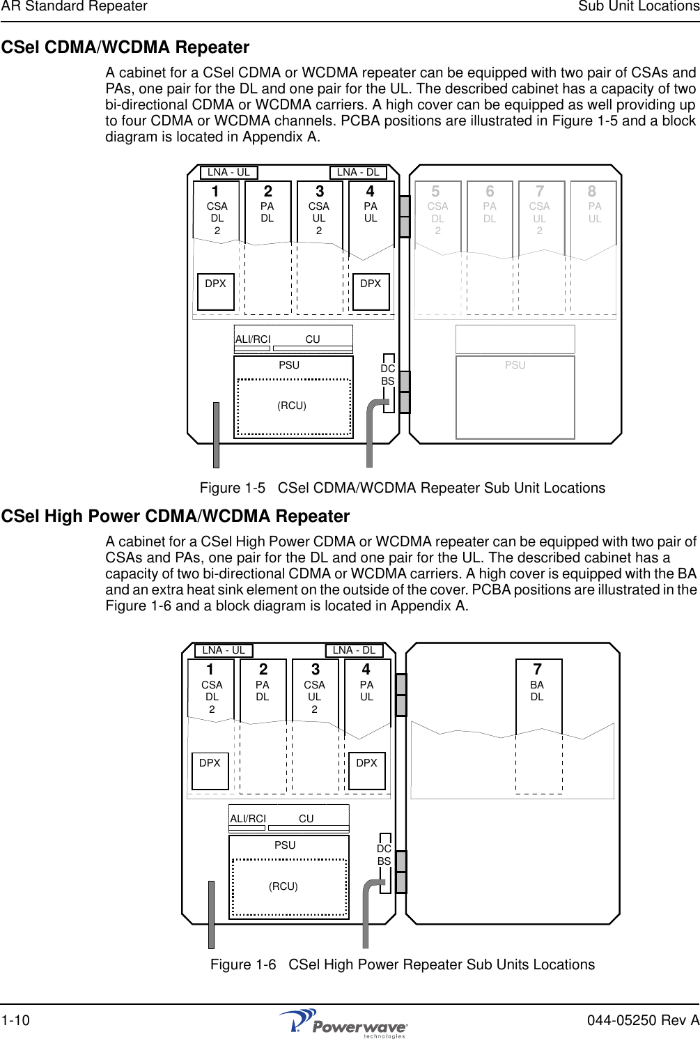
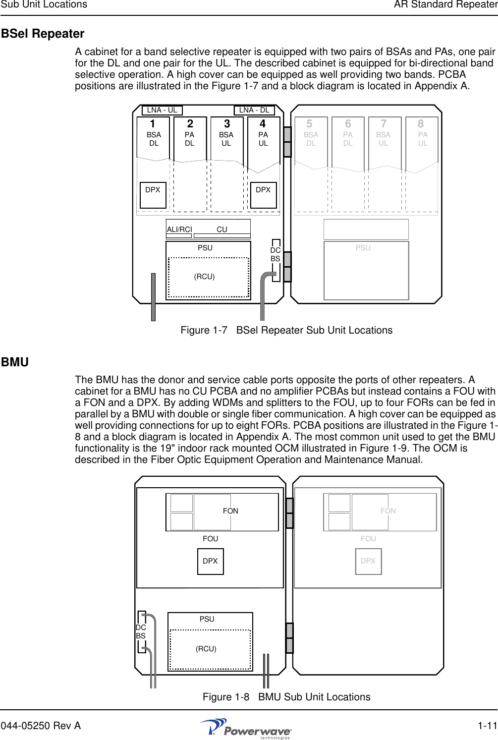
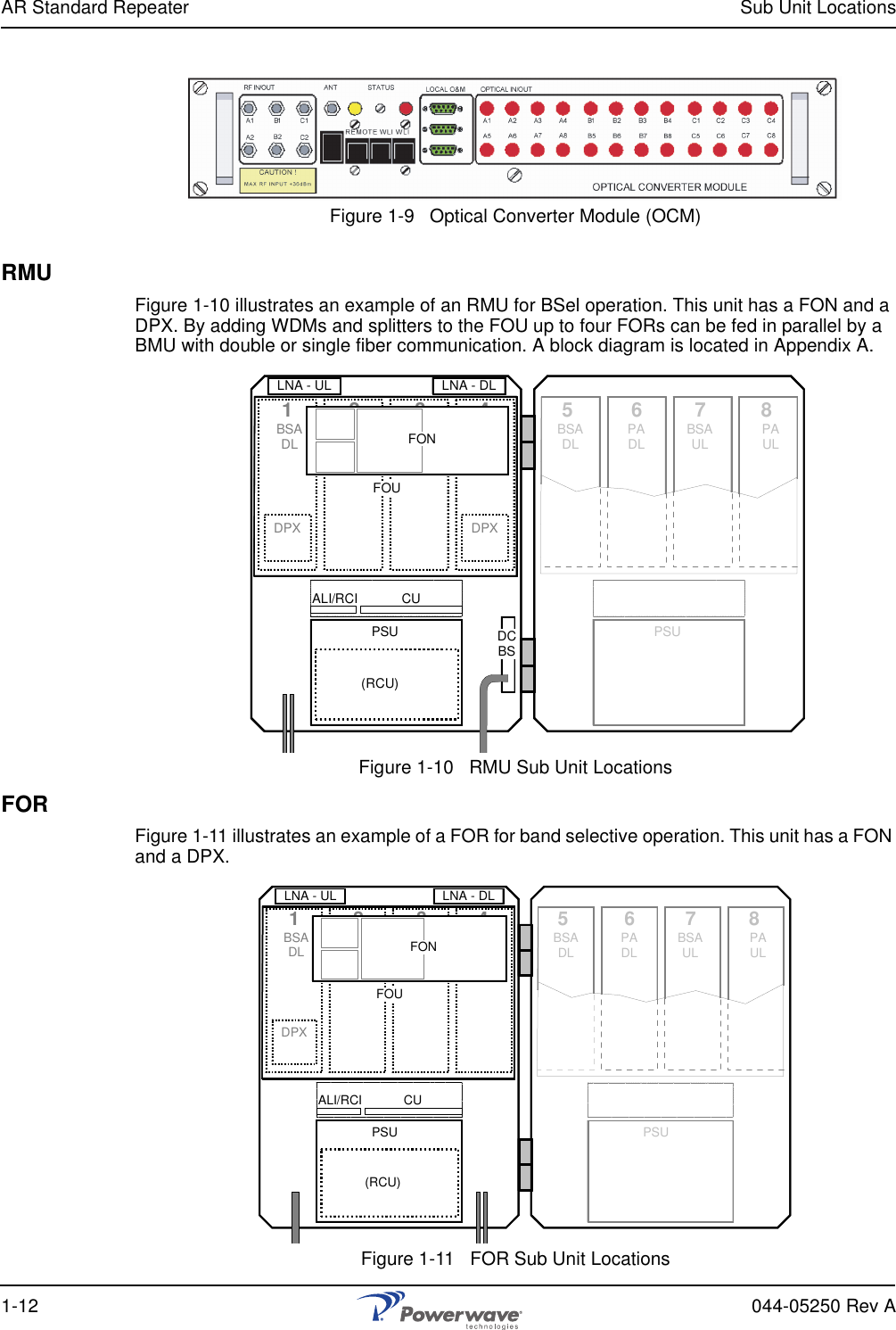
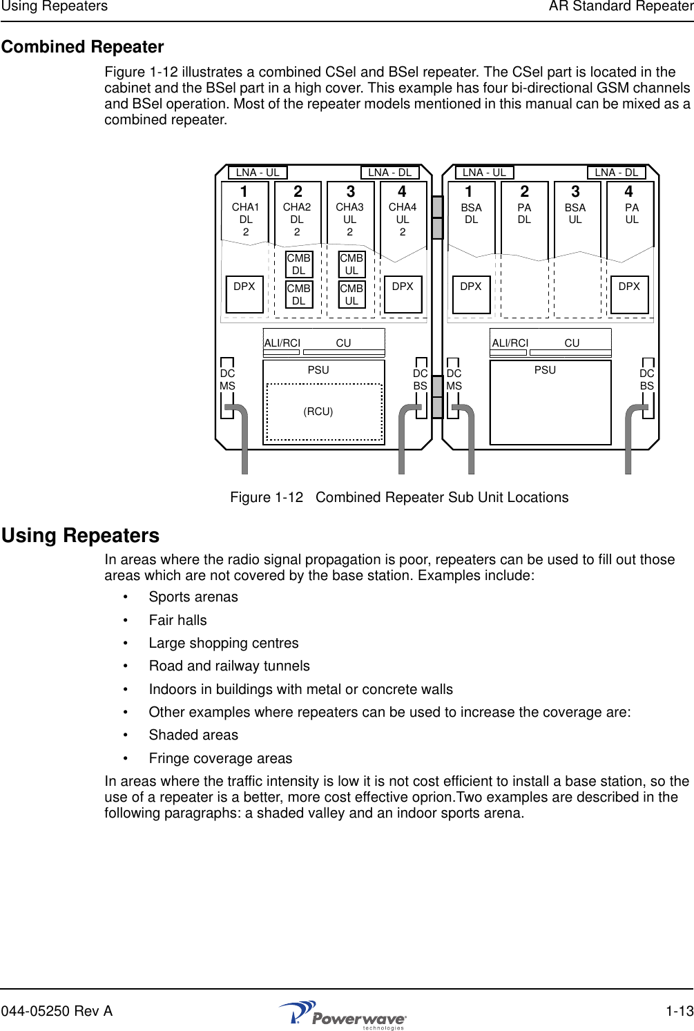
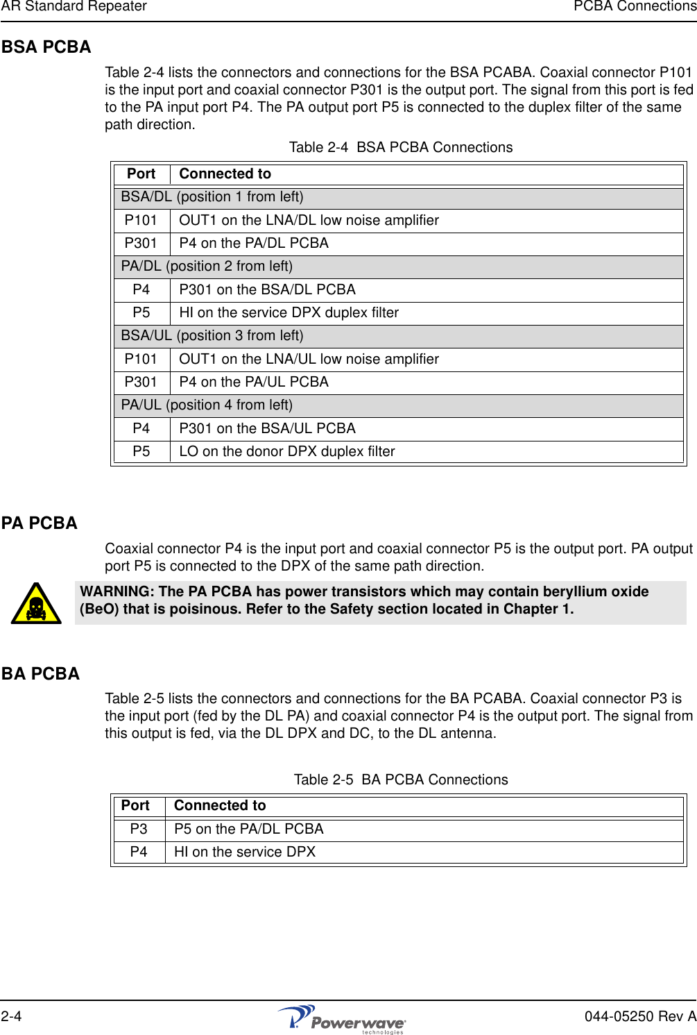
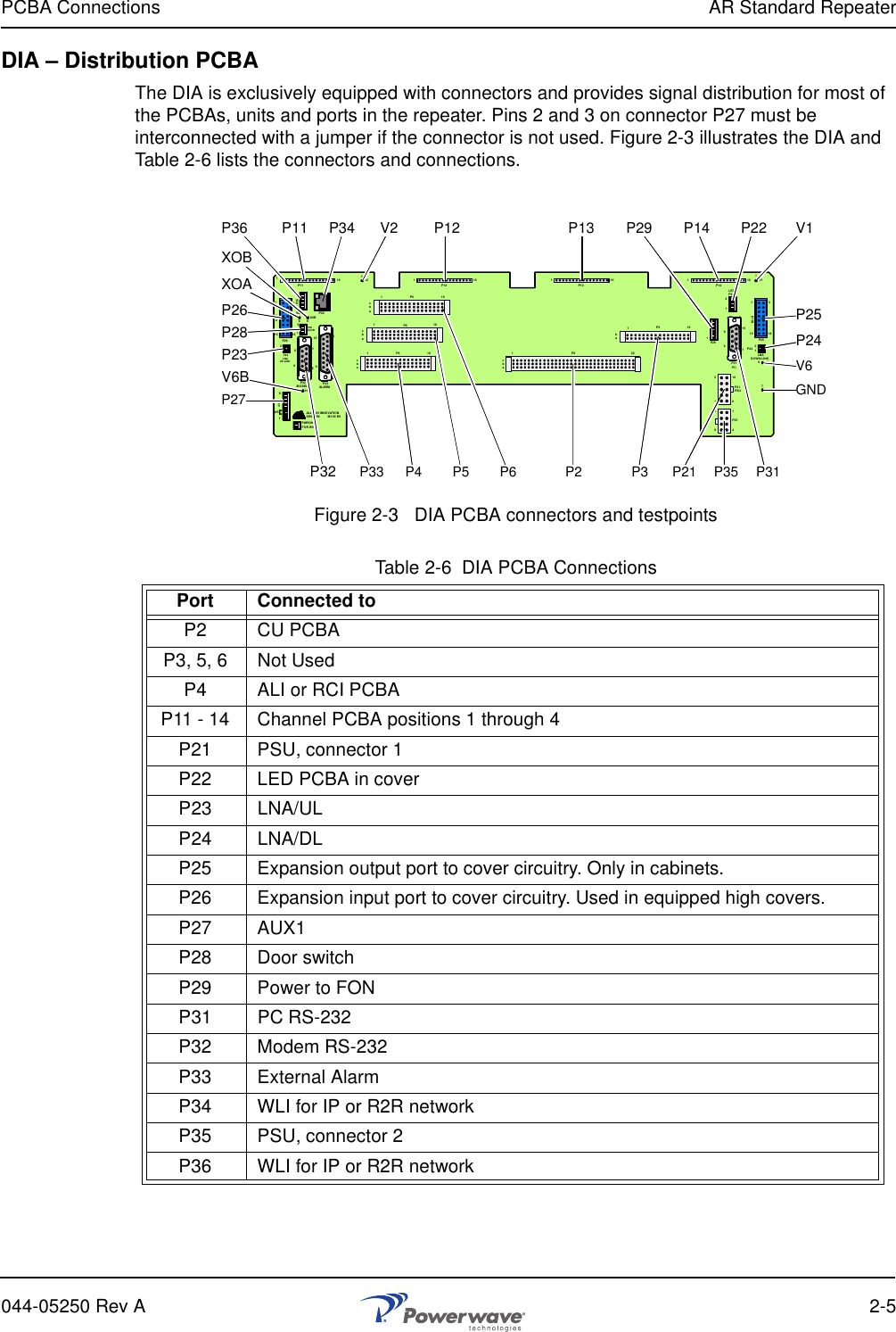
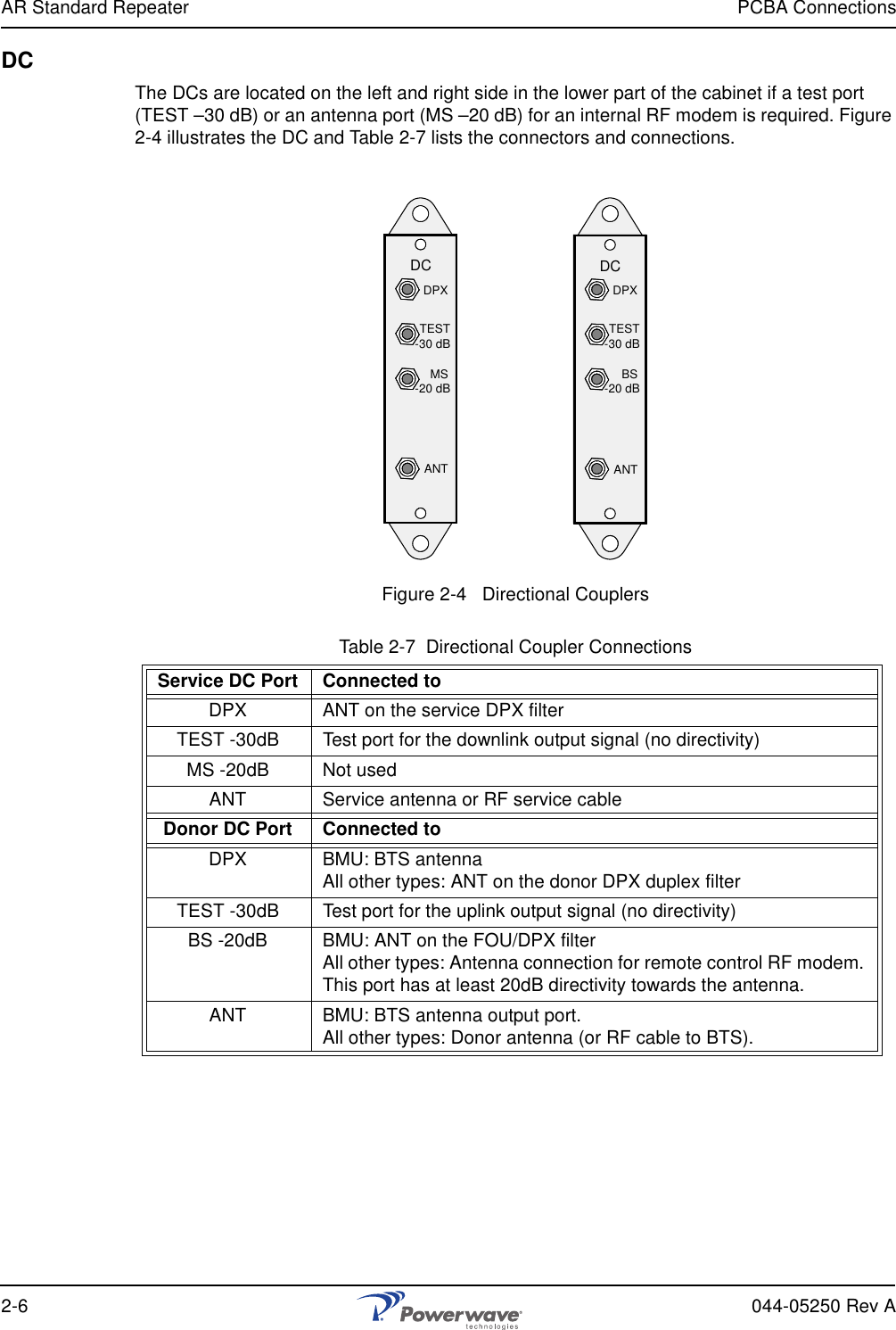
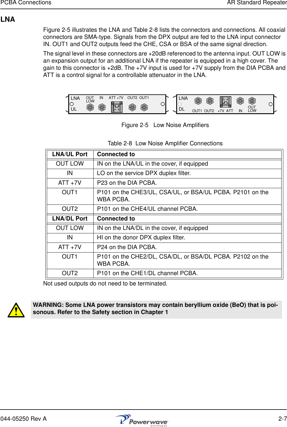
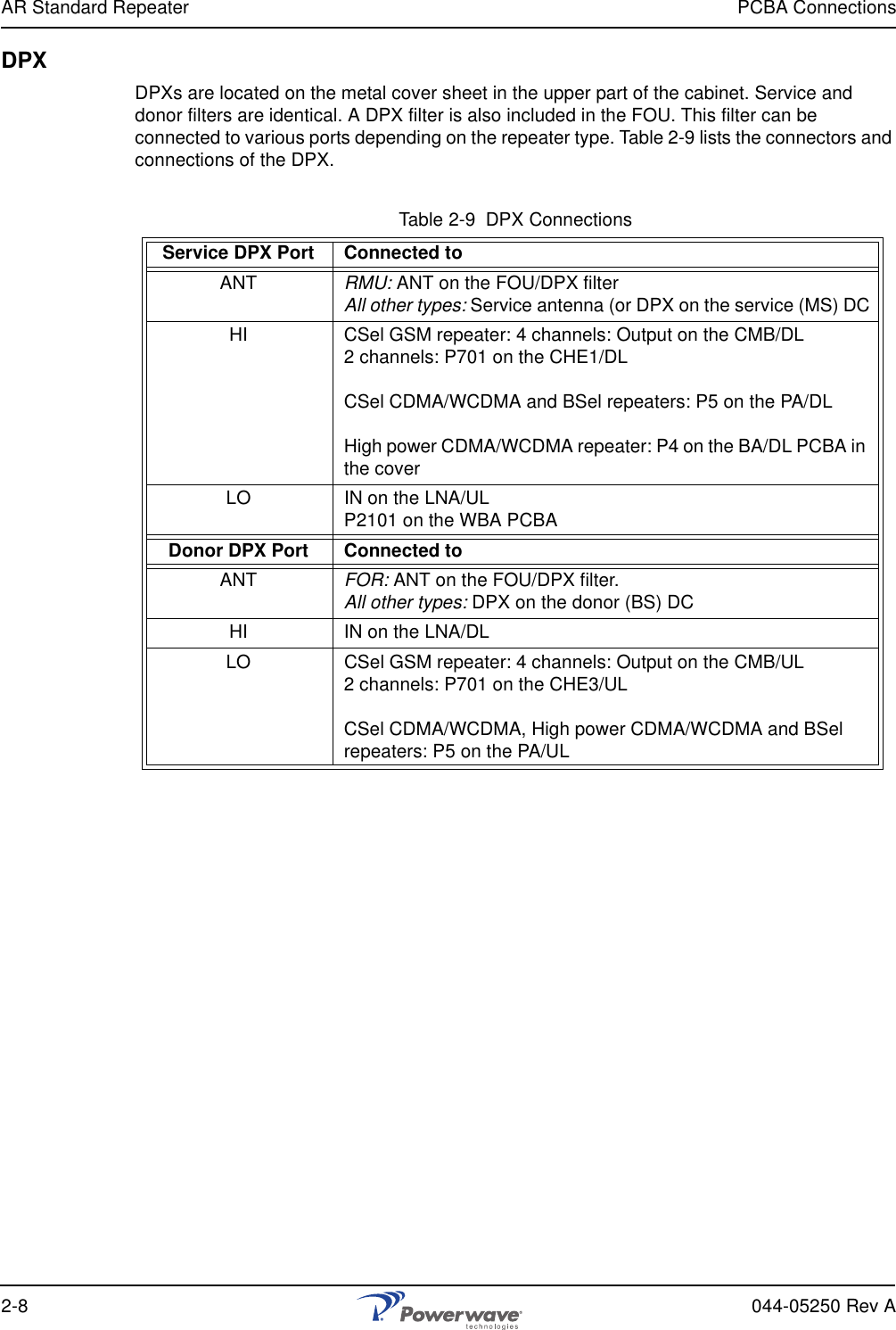
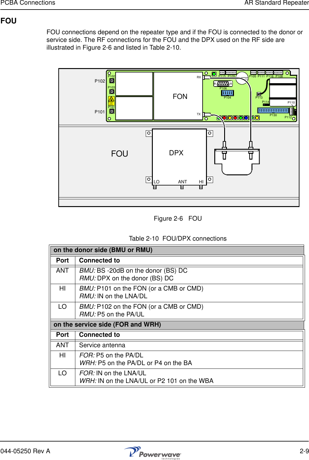
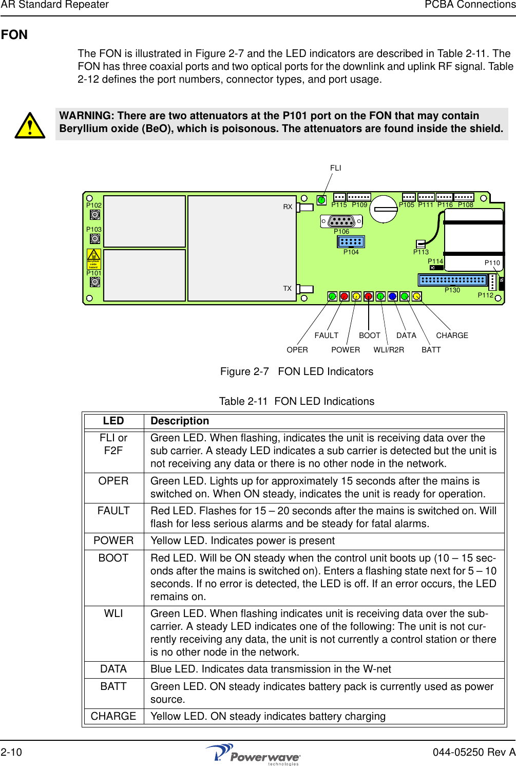
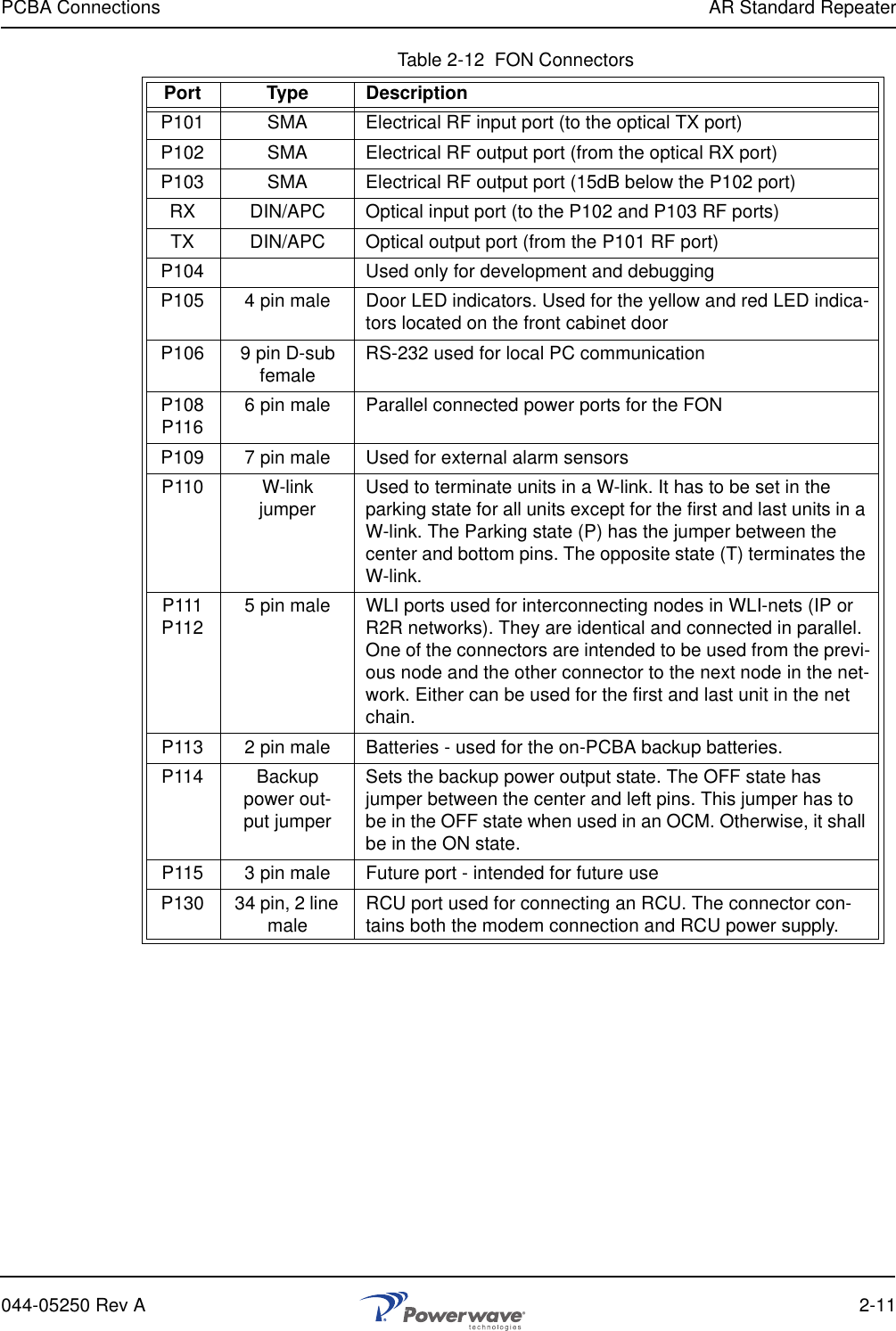
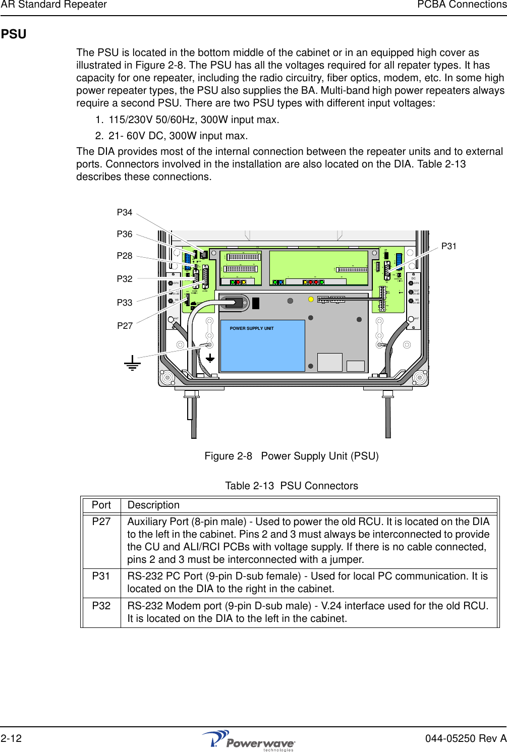
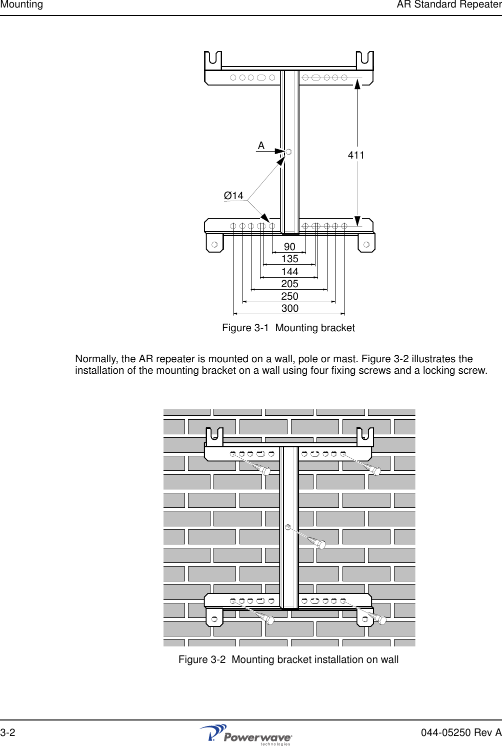
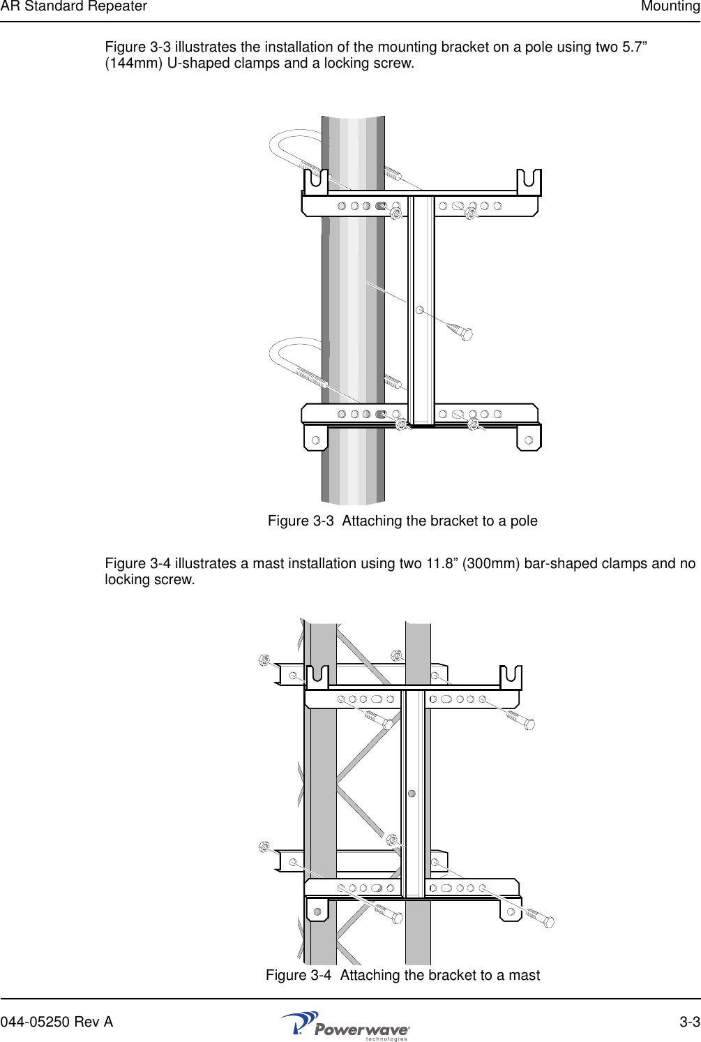
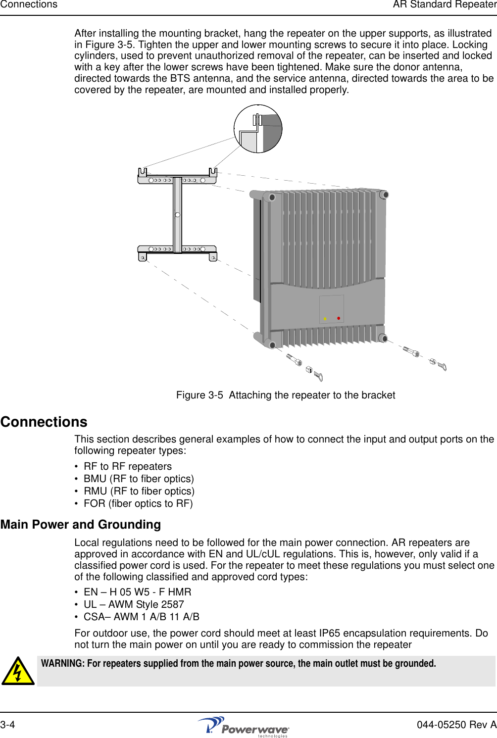
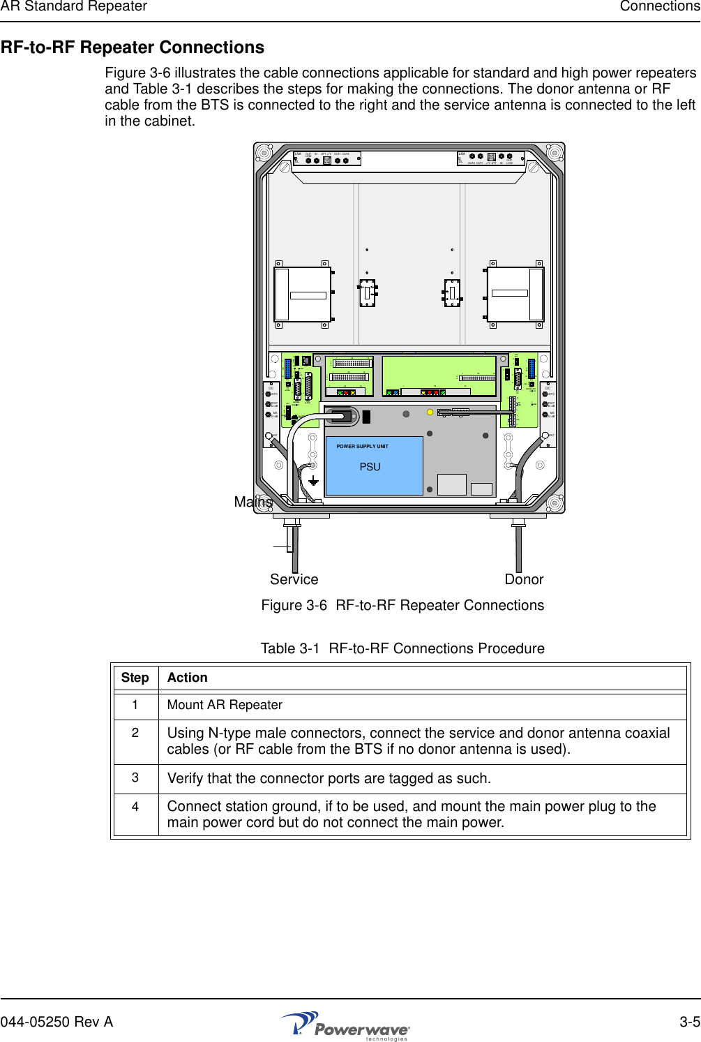
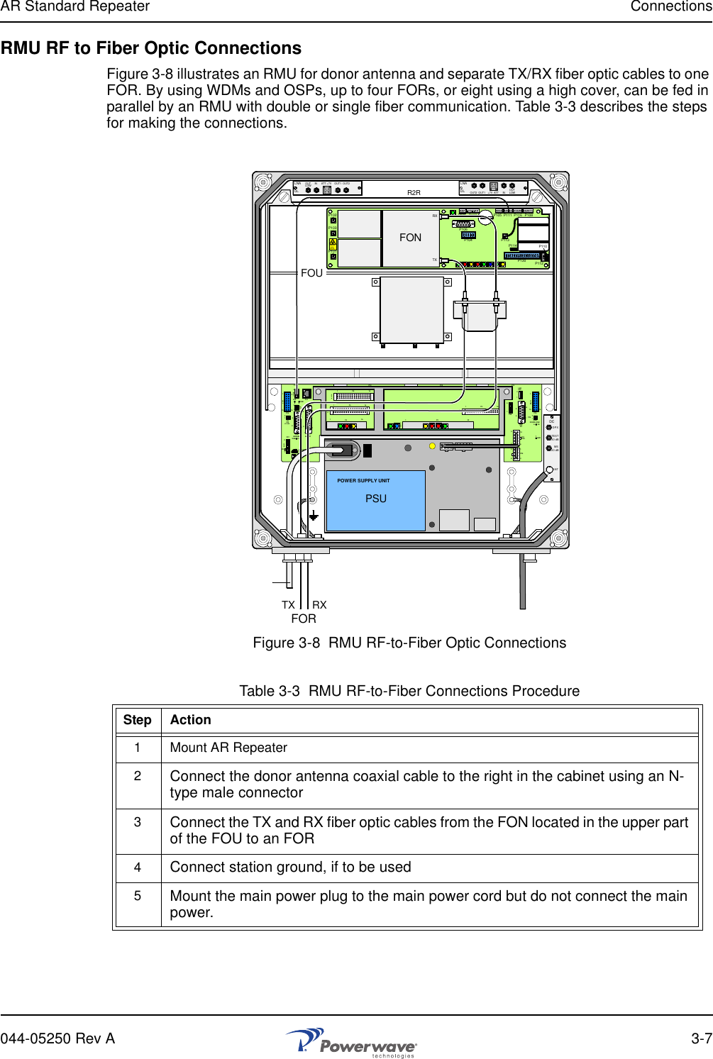
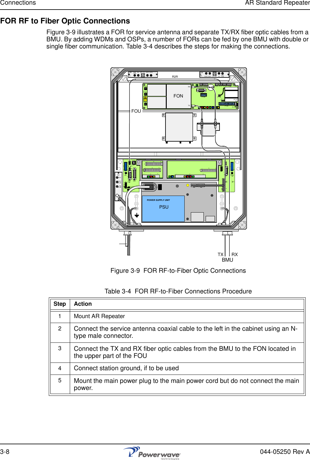
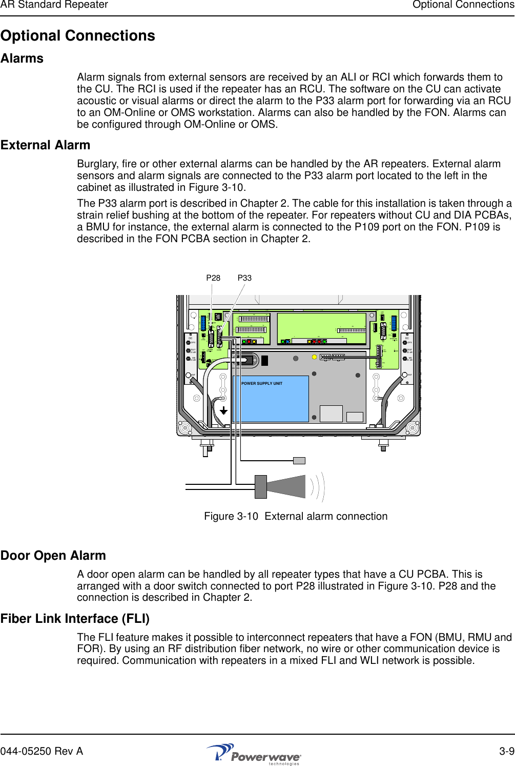
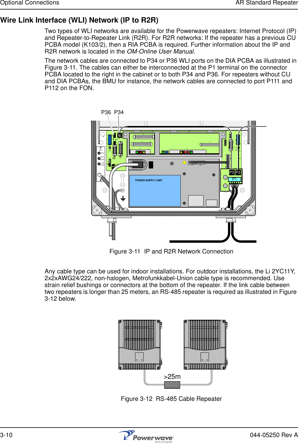
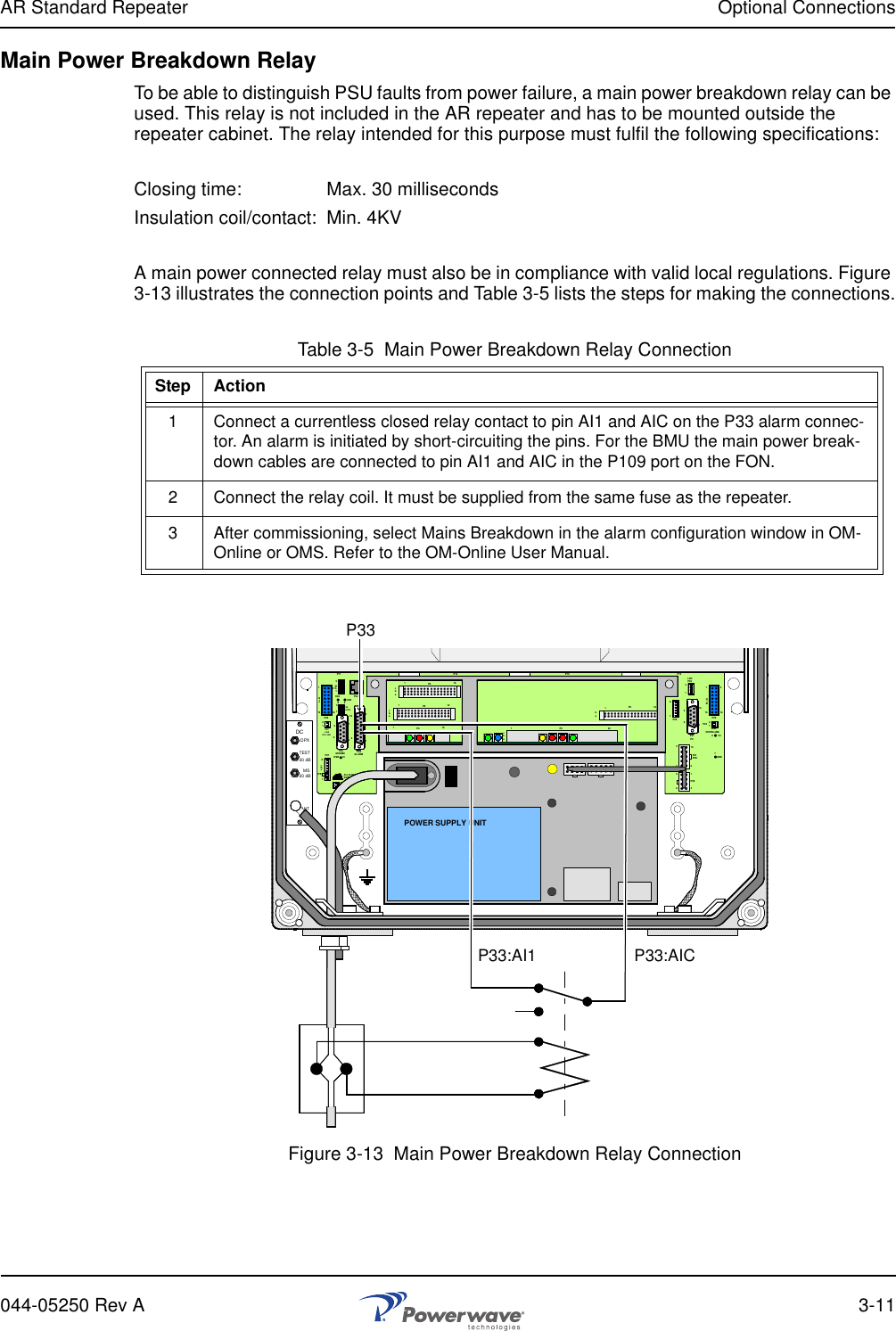
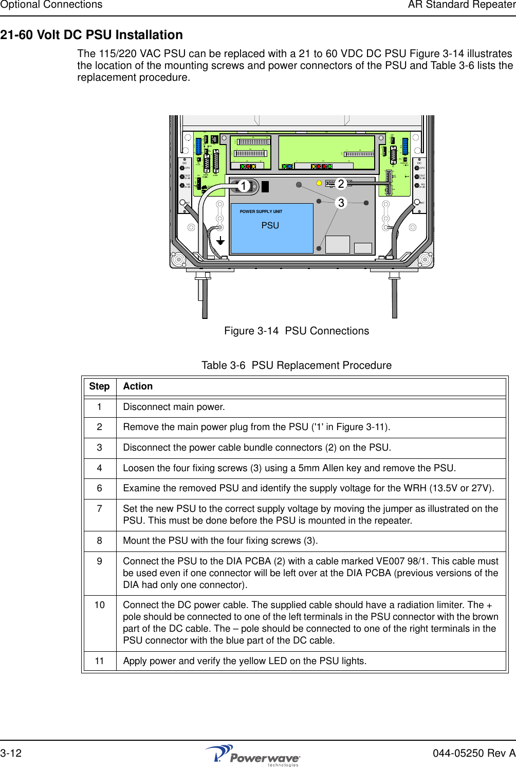
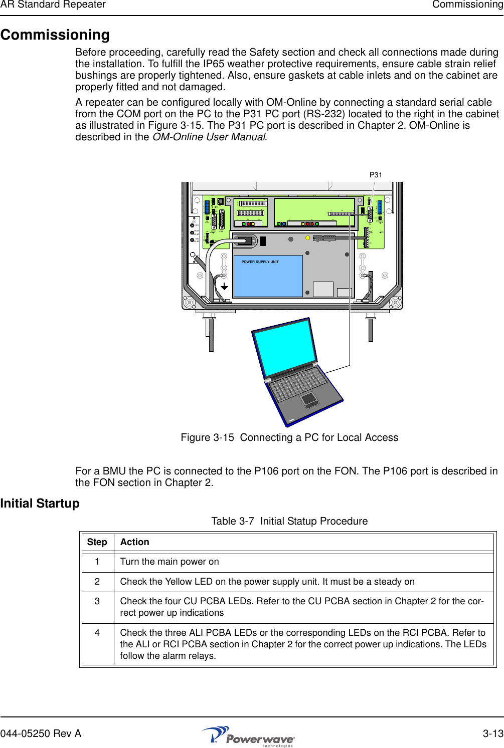
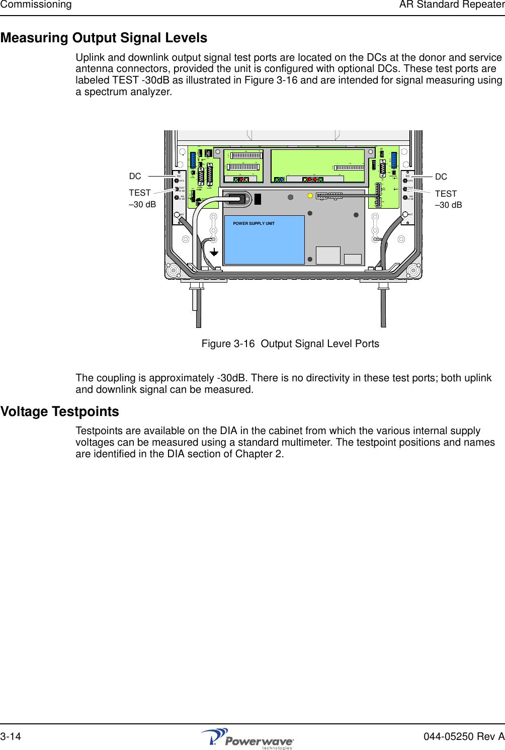
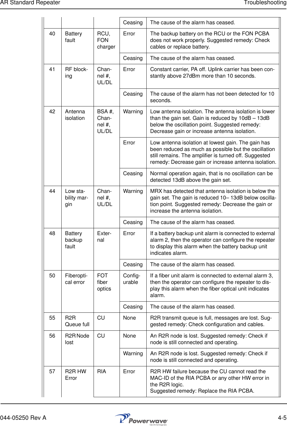
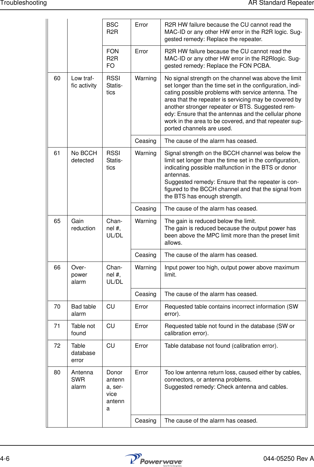
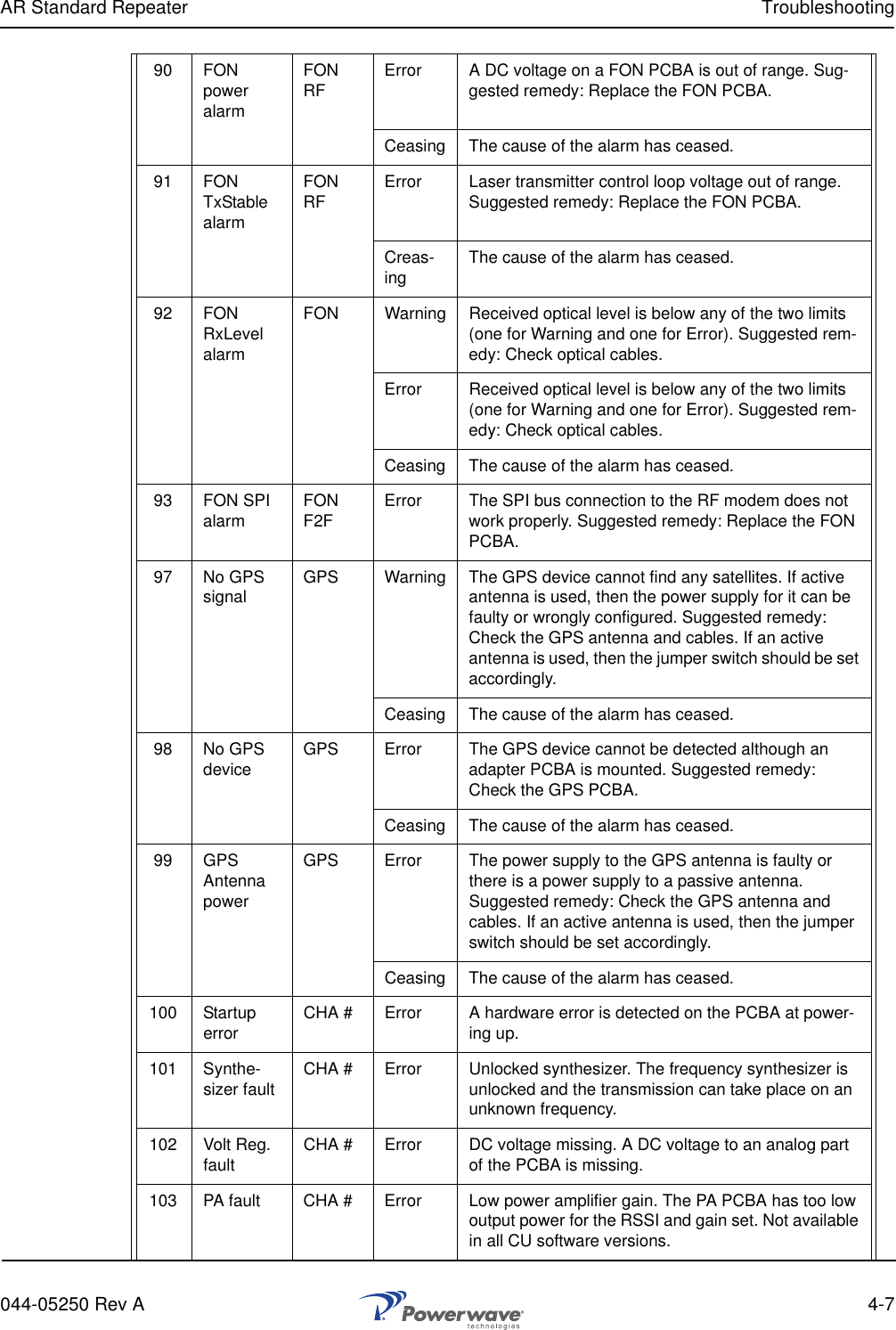
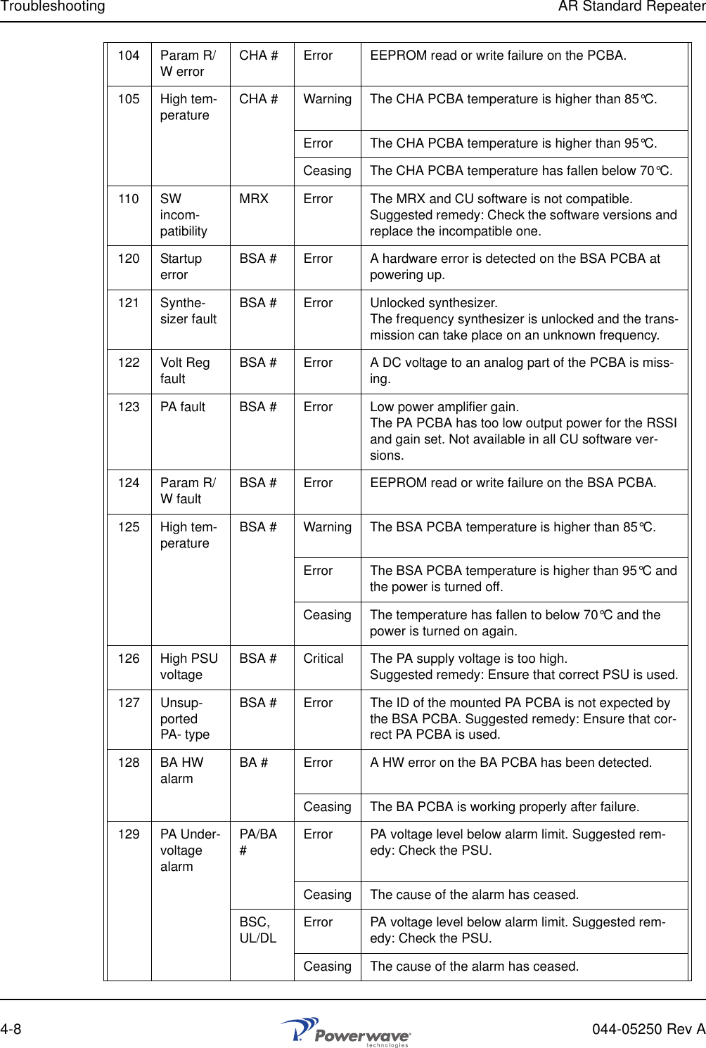
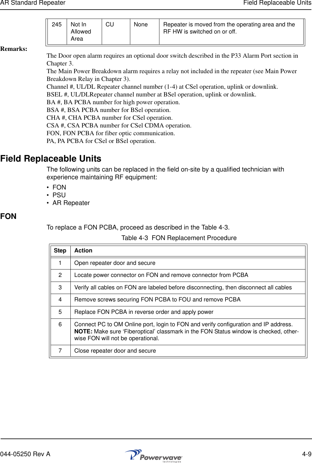
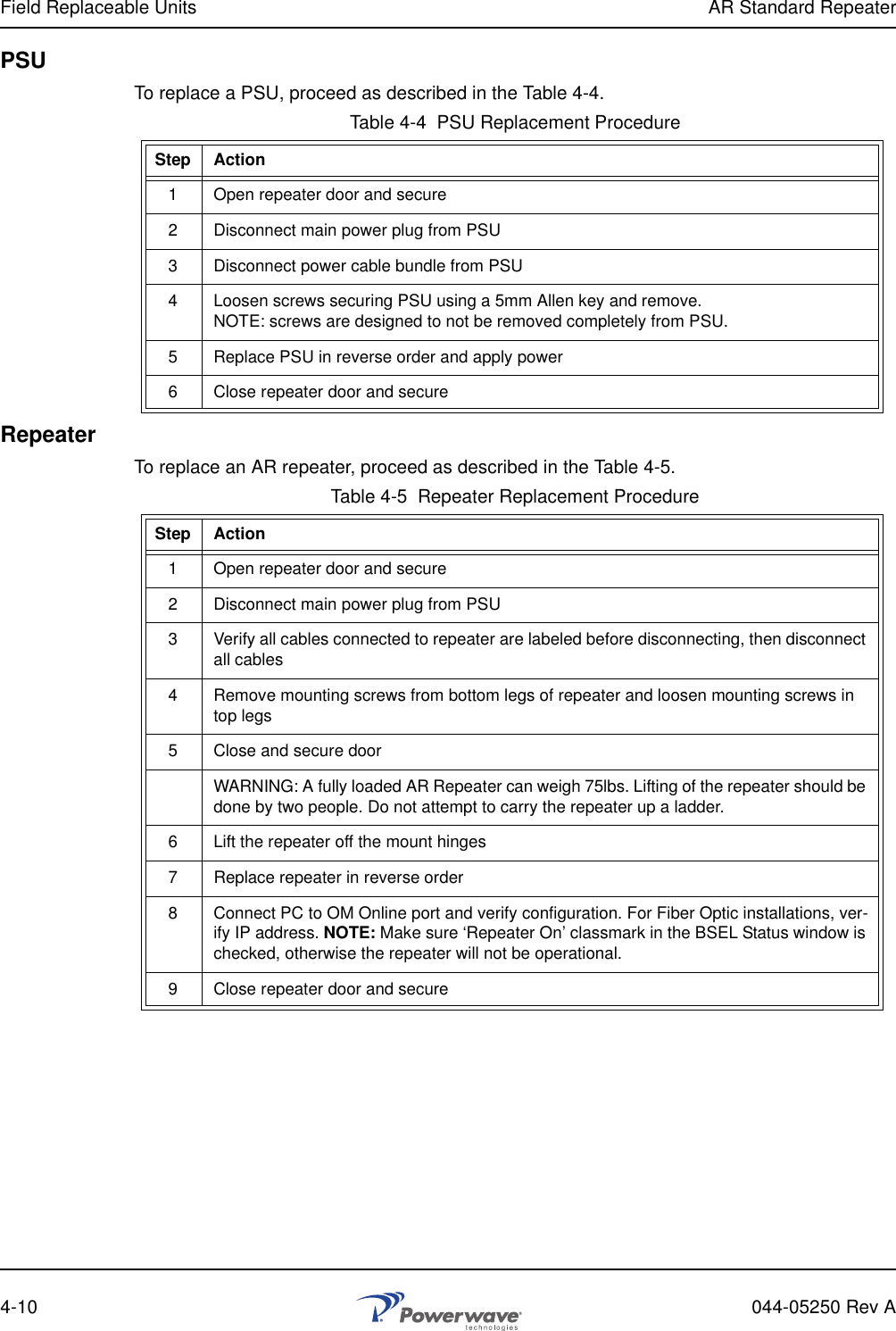
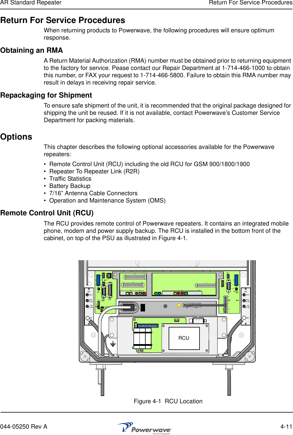
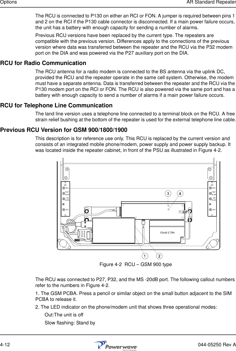
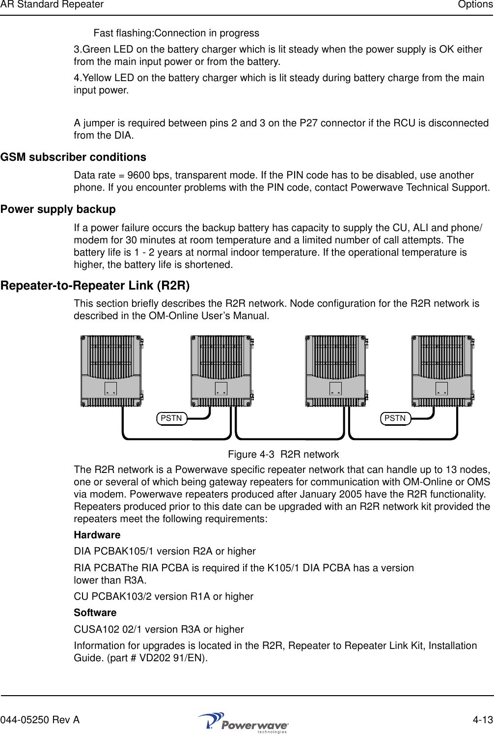
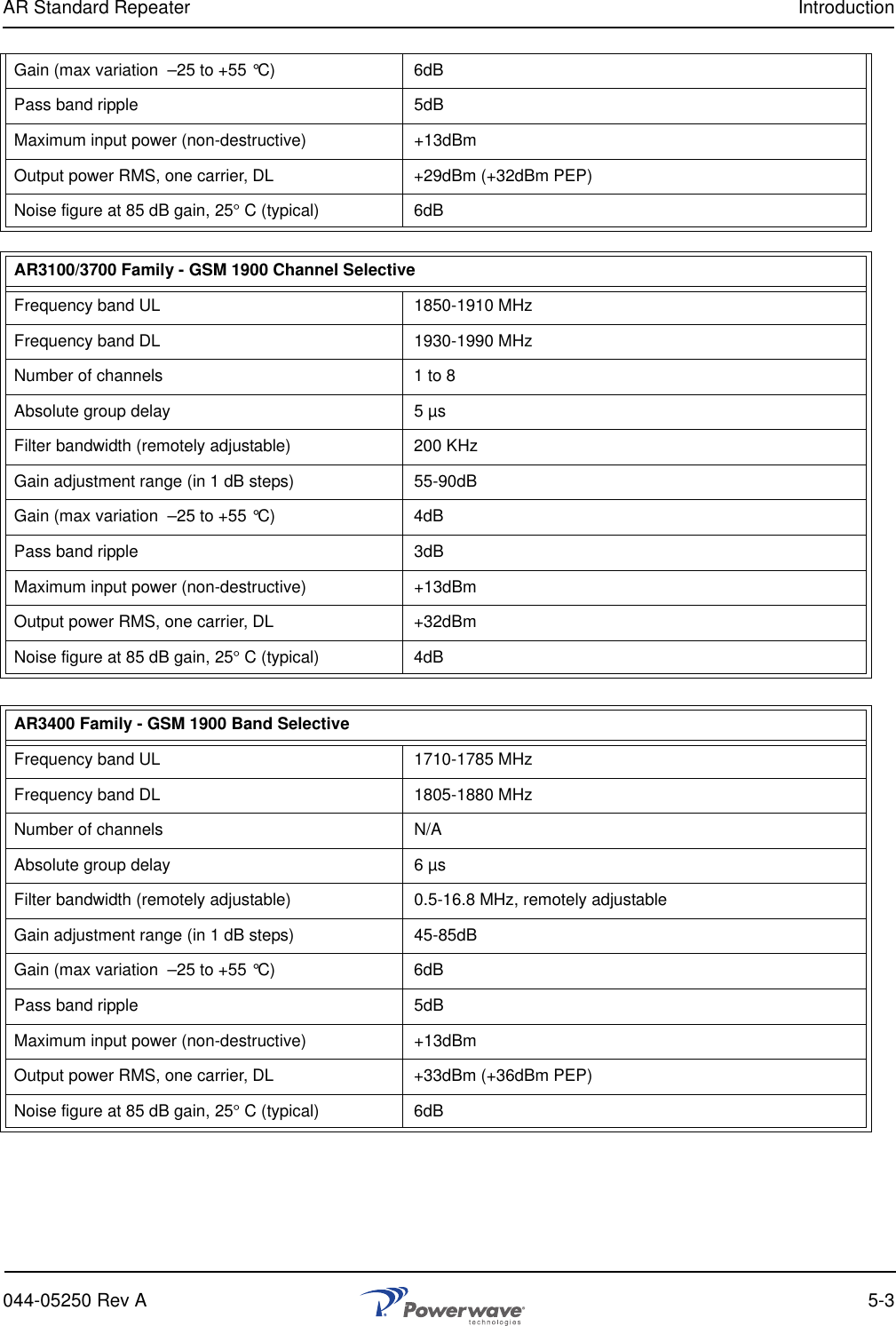
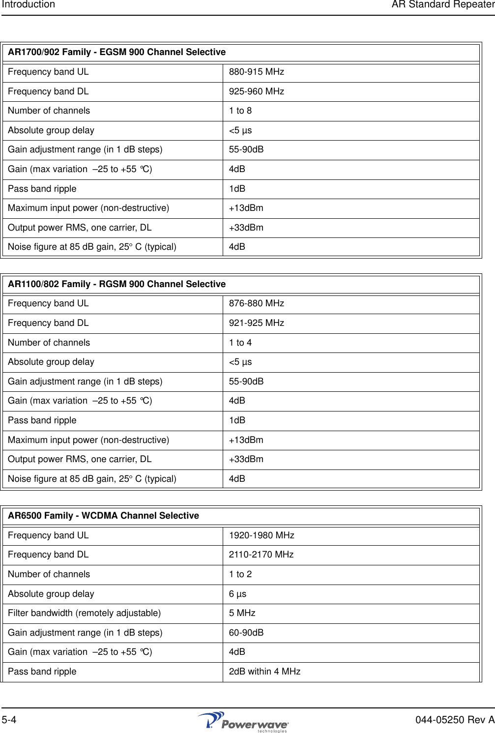
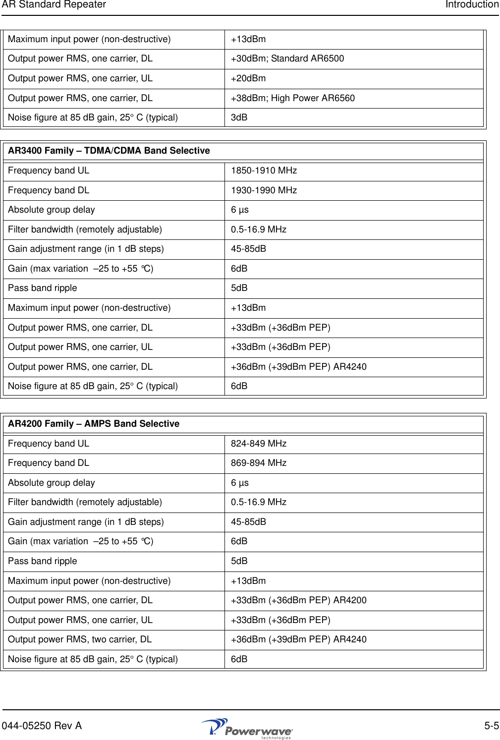
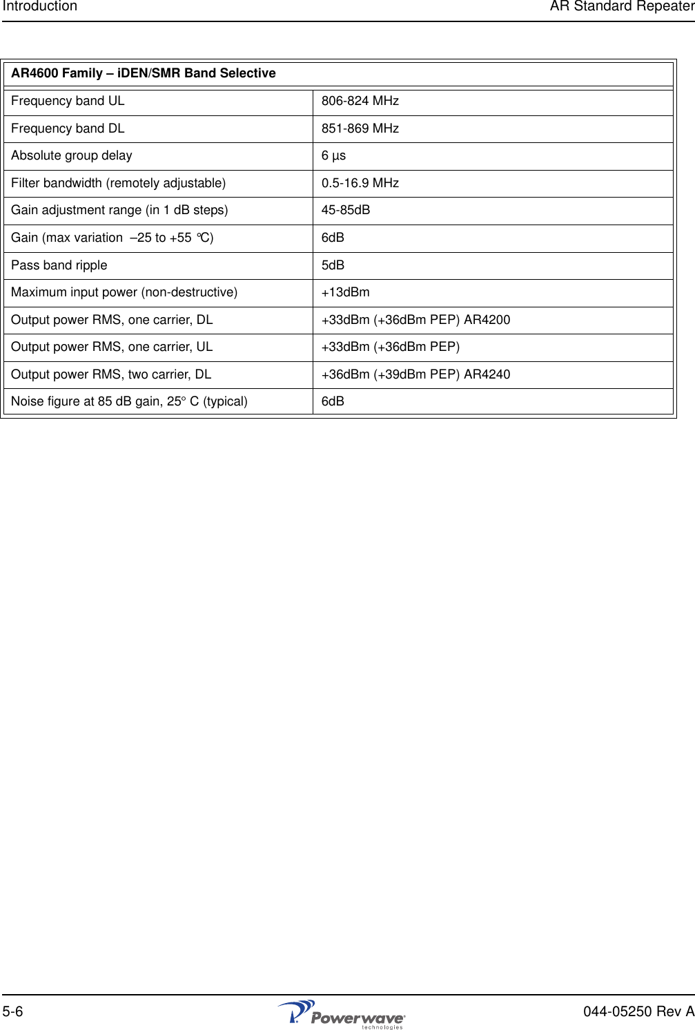
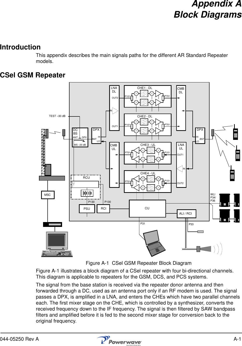
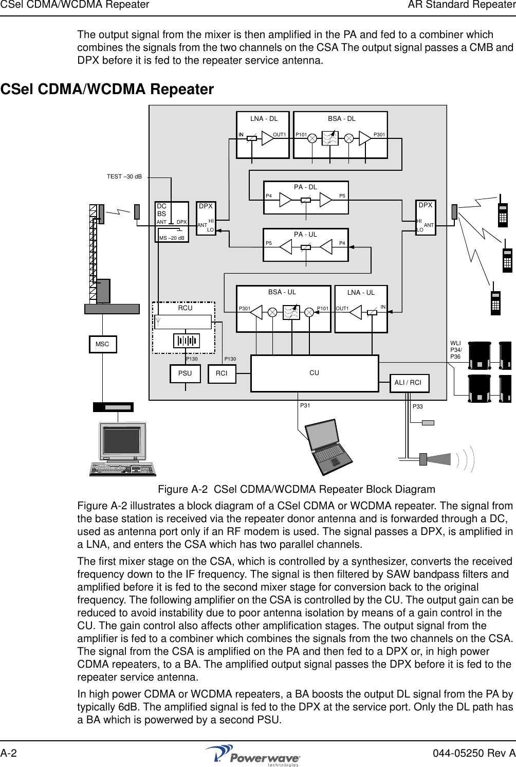
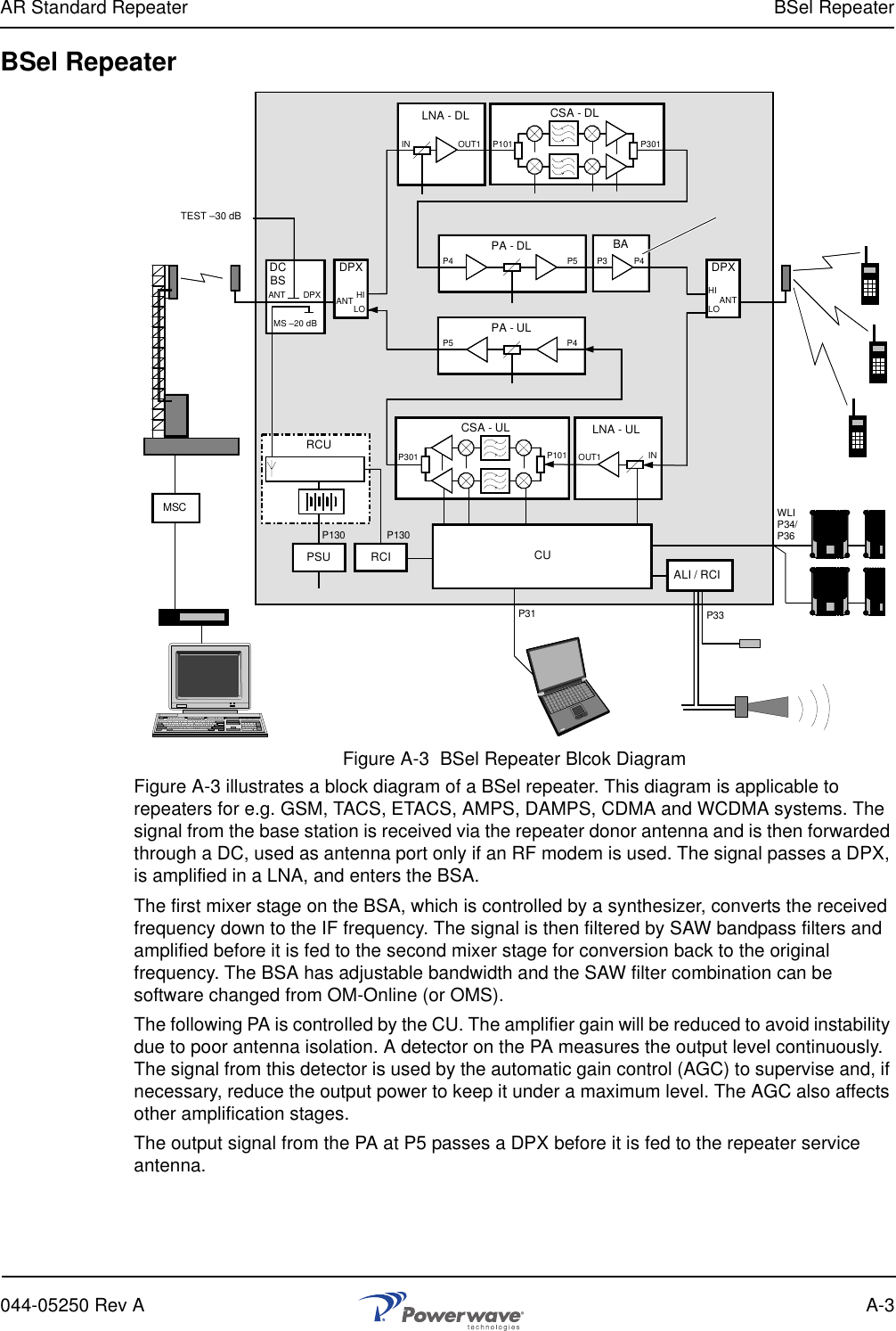
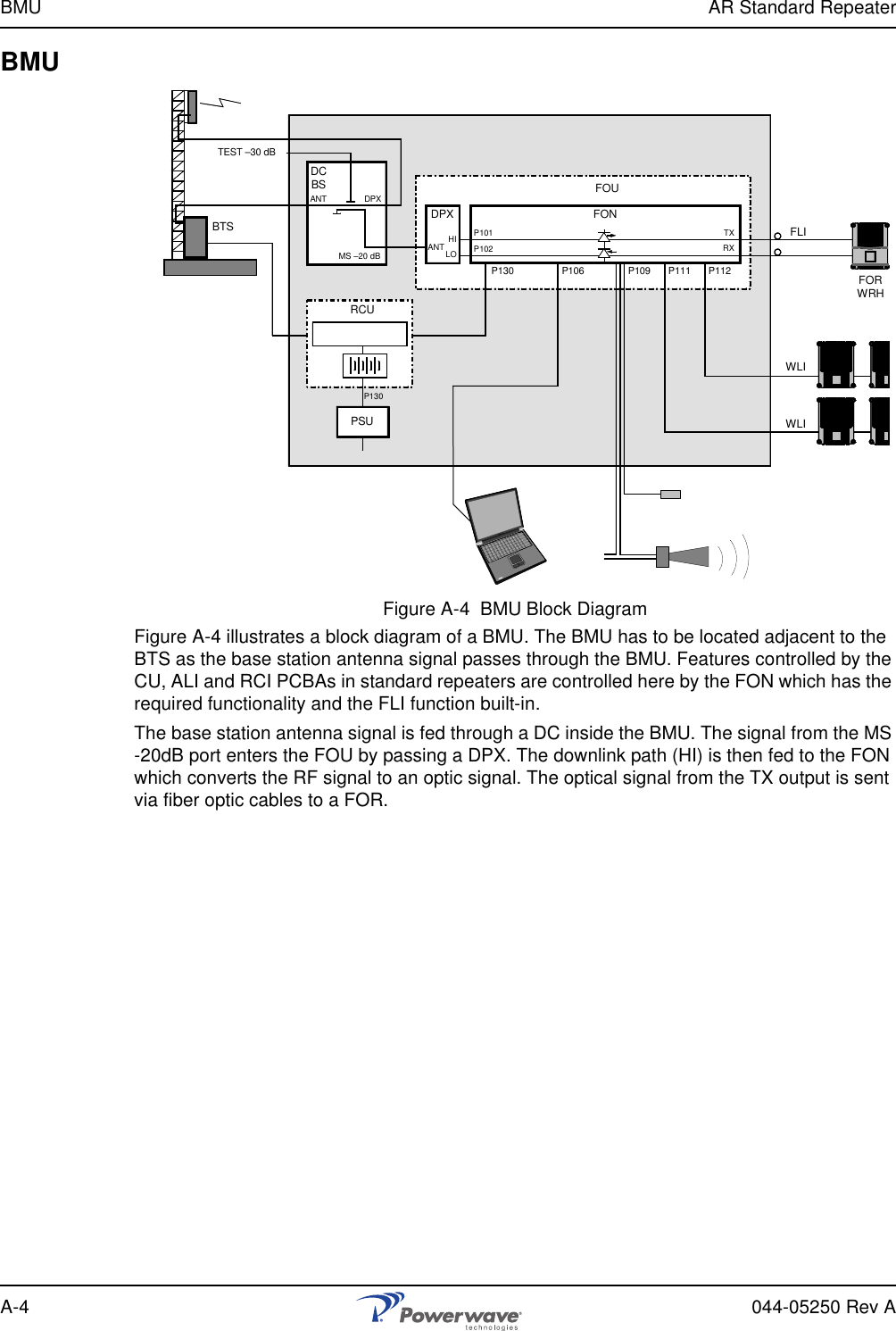
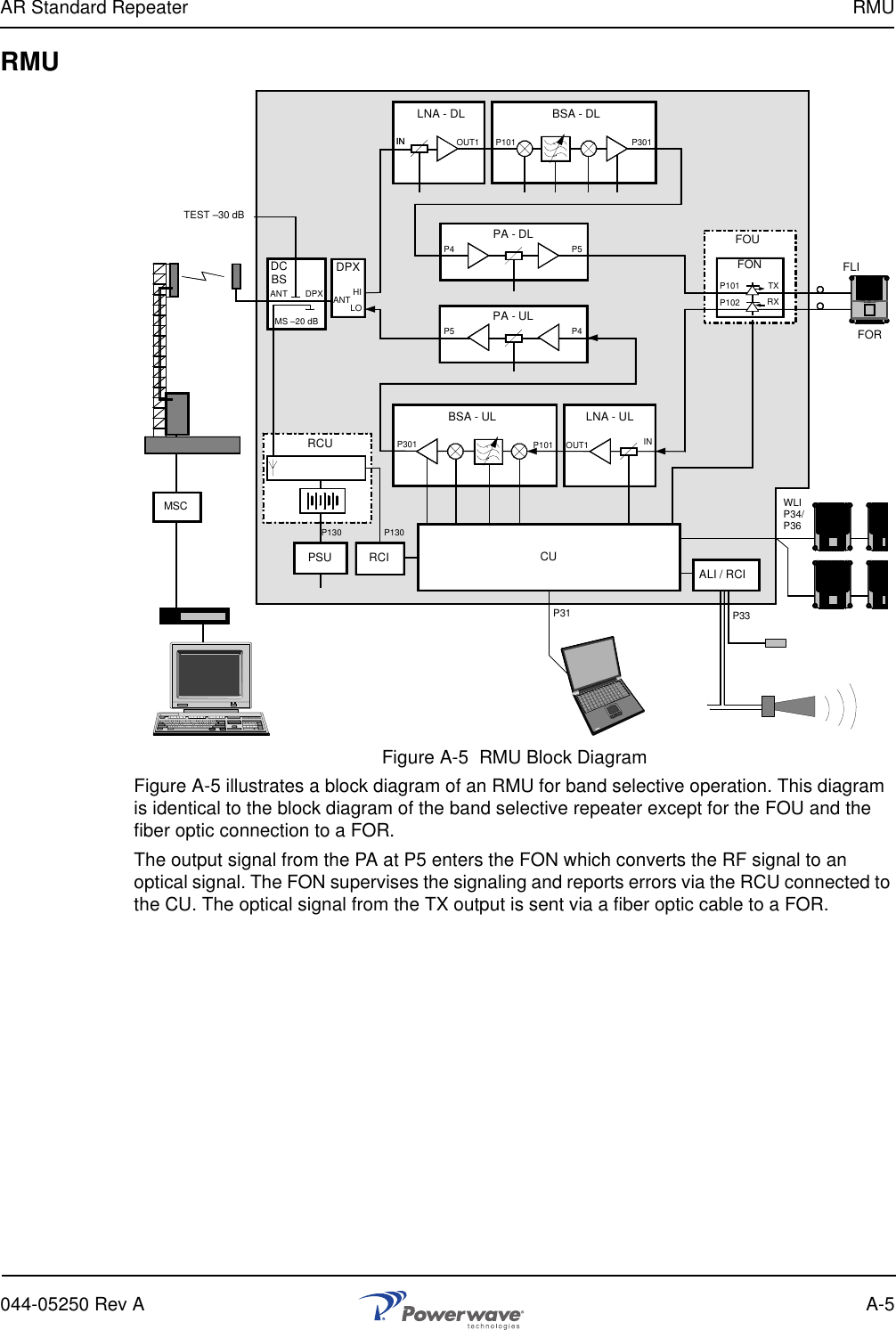
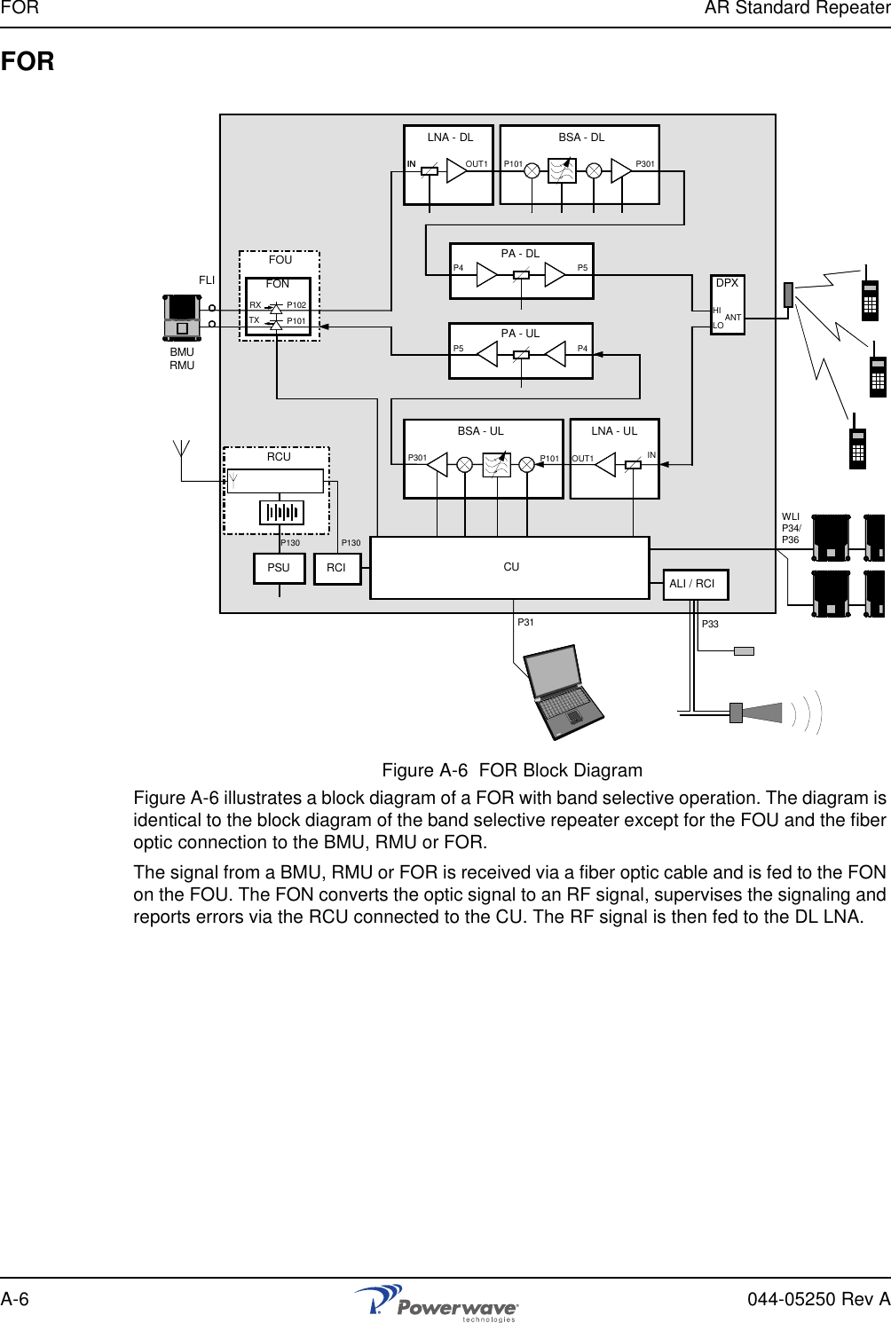
Users Manual