Powerwave Technologies 5JS0093 800 MHz Band Selective Repeater User Manual 044 05250 AR Standard Repeater
Powerwave Technologies Inc 800 MHz Band Selective Repeater 044 05250 AR Standard Repeater
Contents
- 1. Users Manual
- 2. FCC Statement
Users Manual
044-05250 Rev A
February 2007
Installation and Service Manual
AR Standard Repeater

© 2007 Powerwave Technologies Incorporated. All rights reserved.
Powerwave Technologies and the Powerwave logo are registered trademarks.
Powerwave Technologies Inc. reserves the right to make changes to the documentation and equipment, includ-
ing but not limited to component substitution and circuitry changes. Changes that impact this document may
subsequently be incorporated in a later revision of this document.
This Powerwave product is designed to operate within the Normal Operating (typical operating) ranges or con-
ditions specified in this document. Operation of this equipment beyond the specified ranges in this document
may cause (1) spurious emissions that violate regulatory requirements; (2) the equipment to be automatically
removed from service when maximum thresholds are exceeded; or (3) the equipment to not perform in accor-
dance with its specifications. It is the Operator's responsibility to ensure this equipment is properly installed and
operated within Powerwave operating specifications to obtain proper performance from the equipment and to
comply with regulatory requirements.
Federal Communications Commission (FCC)
This equipment has been tested and found to comply with the limits for a Class A digital device, pursuant to
part 15 of the FCC Rules. These limits are designed to provide reasonable protection against harmful interfer-
ence when the equipment is operated in a commercial environment. This equipment generates, uses, and can
radiate radio frequency energy and, if not installed and used in accordance with the instruction manual, may
cause harmful interference to radio communications. Operation of this equipment in a residential area is likely
to cause harmful interference in which case the user will be required to correct the interference at his own
expense.
Industry Canadian Requirement
All Powerwave apparatus introduced on the Canadian market meet all requirements of the Canadian Interfer-
ence-Causing Equipment Regulations.
Powerwave Technologies Inc., 1801 East St. Andrew Place, CA 92705 Santa Ana, USA.
Phone +1 714 466 1000 – Fax +1 714 466 5800 – Internet www.powerwave.com

AR Standard Repeater Revision Record
044-05250 Rev A i
Revision Record
Revision Letter Date of Change Reason for Change
3A August 2005 Original VD203 66
A February 2007 Document number changed to 044-05250 and manual updated

ii 044-05250 Rev A
This Page Intentionally Left Bank

044-05250 Rev A i
Table of Contents
Abbreviations. . . . . . . . . . . . . . . . . . . . . . . . . . . . . . . . . . . . . . . . . . . . . . . . . . . . . . . . . . . . . . . . . . . . . . . . vi
Chapter 1 - Product Description
Introduction . . . . . . . . . . . . . . . . . . . . . . . . . . . . . . . . . . . . . . . . . . . . . . . . . . . . . . . . . . . . . . . . . . . . . . . .1-1
Scope of Manual . . . . . . . . . . . . . . . . . . . . . . . . . . . . . . . . . . . . . . . . . . . . . . . . . . . . . . . . . . . . . . . . . . . .1-1
Safety . . . . . . . . . . . . . . . . . . . . . . . . . . . . . . . . . . . . . . . . . . . . . . . . . . . . . . . . . . . . . . . . . . . . . . . . . . . .1-1
Warning Signs. . . . . . . . . . . . . . . . . . . . . . . . . . . . . . . . . . . . . . . . . . . . . . . . . . . . . . . . . . . . . . . . . . .1-2
Human Exposure of RF Radiation . . . . . . . . . . . . . . . . . . . . . . . . . . . . . . . . . . . . . . . . . . . . . . . . . . .1-2
Repeater Antennas. . . . . . . . . . . . . . . . . . . . . . . . . . . . . . . . . . . . . . . . . . . . . . . . . . . . . . . . . . . .1-2
Installation and Maintenance of Antenna Systems. . . . . . . . . . . . . . . . . . . . . . . . . . . . . . . . . . . .1-2
Radiation Exposure . . . . . . . . . . . . . . . . . . . . . . . . . . . . . . . . . . . . . . . . . . . . . . . . . . . . . . . . . . .1-2
Radiation Safety Distances . . . . . . . . . . . . . . . . . . . . . . . . . . . . . . . . . . . . . . . . . . . . . . . . . . . . . . . .1-3
Electrostatic Discharge (ESD) . . . . . . . . . . . . . . . . . . . . . . . . . . . . . . . . . . . . . . . . . . . . . . . . . . . . . .1-4
Overview . . . . . . . . . . . . . . . . . . . . . . . . . . . . . . . . . . . . . . . . . . . . . . . . . . . . . . . . . . . . . . . . . . . . . . . . . .1-5
Repeaters with RF / RF Transmission . . . . . . . . . . . . . . . . . . . . . . . . . . . . . . . . . . . . . . . . . . . . . . . .1-5
Channel Selective (CSel) Repeater . . . . . . . . . . . . . . . . . . . . . . . . . . . . . . . . . . . . . . . . . . . . . . .1-5
Band Selective (BSel) Repeater. . . . . . . . . . . . . . . . . . . . . . . . . . . . . . . . . . . . . . . . . . . . . . . . . .1-6
Repeaters with RF / Fiber Optic Transmission . . . . . . . . . . . . . . . . . . . . . . . . . . . . . . . . . . . . . . . . . .1-6
Base Station Master Unit (BMU) . . . . . . . . . . . . . . . . . . . . . . . . . . . . . . . . . . . . . . . . . . . . . . . . .1-6
Repeater Master Unit (RMU) . . . . . . . . . . . . . . . . . . . . . . . . . . . . . . . . . . . . . . . . . . . . . . . . . . . .1-6
Repeater with Fiber Optics / RF Transmission . . . . . . . . . . . . . . . . . . . . . . . . . . . . . . . . . . . . . . . . . .1-6
Combined Repeater . . . . . . . . . . . . . . . . . . . . . . . . . . . . . . . . . . . . . . . . . . . . . . . . . . . . . . . . . . . . . .1-6
Repeater Chassis Design . . . . . . . . . . . . . . . . . . . . . . . . . . . . . . . . . . . . . . . . . . . . . . . . . . . . . . . . . .1-6
Sub Unit Overview. . . . . . . . . . . . . . . . . . . . . . . . . . . . . . . . . . . . . . . . . . . . . . . . . . . . . . . . . . . . . . . . . . .1-7
Channel Amplifier PCBA for GSM and EDGE (CHE) . . . . . . . . . . . . . . . . . . . . . . . . . . . . . . . . . . . . .1-7
CDMA/WCDMA Segment Amplifier PCBA (CSA). . . . . . . . . . . . . . . . . . . . . . . . . . . . . . . . . . . . . . . .1-7
Band Selective Amplifier PCBA (BSA) . . . . . . . . . . . . . . . . . . . . . . . . . . . . . . . . . . . . . . . . . . . . . . . .1-7
Power Amplifier PCBA (PA) . . . . . . . . . . . . . . . . . . . . . . . . . . . . . . . . . . . . . . . . . . . . . . . . . . . . . . . .1-7
Booster Amplifier (BA). . . . . . . . . . . . . . . . . . . . . . . . . . . . . . . . . . . . . . . . . . . . . . . . . . . . . . . . . . . . .1-7
Distribution PCBA (DIA) . . . . . . . . . . . . . . . . . . . . . . . . . . . . . . . . . . . . . . . . . . . . . . . . . . . . . . . . . . .1-7
Control Unit PCBA (CU) . . . . . . . . . . . . . . . . . . . . . . . . . . . . . . . . . . . . . . . . . . . . . . . . . . . . . . . . . . .1-7
Directional Coupler (DC). . . . . . . . . . . . . . . . . . . . . . . . . . . . . . . . . . . . . . . . . . . . . . . . . . . . . . . . . . .1-8
Low Noise Amplifier (LNA) . . . . . . . . . . . . . . . . . . . . . . . . . . . . . . . . . . . . . . . . . . . . . . . . . . . . . . . . .1-8
Duplex filter (DPX) . . . . . . . . . . . . . . . . . . . . . . . . . . . . . . . . . . . . . . . . . . . . . . . . . . . . . . . . . . . . . . .1-8
Fiber Optic Unit (FOU) . . . . . . . . . . . . . . . . . . . . . . . . . . . . . . . . . . . . . . . . . . . . . . . . . . . . . . . . . . . .1-8
Fiber Optic Node (FON) . . . . . . . . . . . . . . . . . . . . . . . . . . . . . . . . . . . . . . . . . . . . . . . . . . . . . . . . . . .1-8
Power Supply Unit (PSU) . . . . . . . . . . . . . . . . . . . . . . . . . . . . . . . . . . . . . . . . . . . . . . . . . . . . . . . . . .1-9
Remote Control Unit (RCU) . . . . . . . . . . . . . . . . . . . . . . . . . . . . . . . . . . . . . . . . . . . . . . . . . . . . . . . .1-9
Combiner unit (CMB) . . . . . . . . . . . . . . . . . . . . . . . . . . . . . . . . . . . . . . . . . . . . . . . . . . . . . . . . . . . . .1-9
Alarm Interface PCBA (ALI) and Remote Control Interface PCBA (RCI) . . . . . . . . . . . . . . . . . . . . . .1-9
Repeater-to-Repeater Interface Adapter (RIA) . . . . . . . . . . . . . . . . . . . . . . . . . . . . . . . . . . . . . . . . . .1-9
Sub Unit Locations . . . . . . . . . . . . . . . . . . . . . . . . . . . . . . . . . . . . . . . . . . . . . . . . . . . . . . . . . . . . . . . . . .1-9
CSel GSM Repeater . . . . . . . . . . . . . . . . . . . . . . . . . . . . . . . . . . . . . . . . . . . . . . . . . . . . . . . . . . . . . .1-9
CSel CDMA/WCDMA Repeater . . . . . . . . . . . . . . . . . . . . . . . . . . . . . . . . . . . . . . . . . . . . . . . . . . . .1-10
CSel High Power CDMA/WCDMA Repeater . . . . . . . . . . . . . . . . . . . . . . . . . . . . . . . . . . . . . . . . . .1-10
BSel Repeater. . . . . . . . . . . . . . . . . . . . . . . . . . . . . . . . . . . . . . . . . . . . . . . . . . . . . . . . . . . . . . . . . .1-11
BMU . . . . . . . . . . . . . . . . . . . . . . . . . . . . . . . . . . . . . . . . . . . . . . . . . . . . . . . . . . . . . . . . . . . . . . . . .1-11
RMU . . . . . . . . . . . . . . . . . . . . . . . . . . . . . . . . . . . . . . . . . . . . . . . . . . . . . . . . . . . . . . . . . . . . . . . . .1-12
FOR. . . . . . . . . . . . . . . . . . . . . . . . . . . . . . . . . . . . . . . . . . . . . . . . . . . . . . . . . . . . . . . . . . . . . . . . . .1-12
Combined Repeater . . . . . . . . . . . . . . . . . . . . . . . . . . . . . . . . . . . . . . . . . . . . . . . . . . . . . . . . . . . . .1-13
Using Repeaters . . . . . . . . . . . . . . . . . . . . . . . . . . . . . . . . . . . . . . . . . . . . . . . . . . . . . . . . . . . . . . . . . . .1-13

Table of Contents AR Standard Repeater
ii 044-05250 Rev A
Shaded Area . . . . . . . . . . . . . . . . . . . . . . . . . . . . . . . . . . . . . . . . . . . . . . . . . . . . . . . . . . . . . . . . . .1-14
Sports Arena . . . . . . . . . . . . . . . . . . . . . . . . . . . . . . . . . . . . . . . . . . . . . . . . . . . . . . . . . . . . . . . . . . .1-15
Fiber Optic Distribution Networks . . . . . . . . . . . . . . . . . . . . . . . . . . . . . . . . . . . . . . . . . . . . . . . . . . .1-16
Multi-Operator Configurations . . . . . . . . . . . . . . . . . . . . . . . . . . . . . . . . . . . . . . . . . . . . . . . . . . . . .1-17
Chapter 2 - Controls, Connections and Indicators
Introduction . . . . . . . . . . . . . . . . . . . . . . . . . . . . . . . . . . . . . . . . . . . . . . . . . . . . . . . . . . . . . . . . . . . . . . . .2-1
Front Cover LED Indicators . . . . . . . . . . . . . . . . . . . . . . . . . . . . . . . . . . . . . . . . . . . . . . . . . . . . . . . . . . . .2-1
Cabinet LED Indicators . . . . . . . . . . . . . . . . . . . . . . . . . . . . . . . . . . . . . . . . . . . . . . . . . . . . . . . . . . . . . . .2-1
PCBA Connections . . . . . . . . . . . . . . . . . . . . . . . . . . . . . . . . . . . . . . . . . . . . . . . . . . . . . . . . . . . . . . . . . .2-2
CHE PCBA . . . . . . . . . . . . . . . . . . . . . . . . . . . . . . . . . . . . . . . . . . . . . . . . . . . . . . . . . . . . . . . . . . . . .2-2
CSA PCBA . . . . . . . . . . . . . . . . . . . . . . . . . . . . . . . . . . . . . . . . . . . . . . . . . . . . . . . . . . . . . . . . . . . . .2-3
2-3
BSA PCBA . . . . . . . . . . . . . . . . . . . . . . . . . . . . . . . . . . . . . . . . . . . . . . . . . . . . . . . . . . . . . . . . . . . . .2-4
2-4
PA PCBA . . . . . . . . . . . . . . . . . . . . . . . . . . . . . . . . . . . . . . . . . . . . . . . . . . . . . . . . . . . . . . . . . . . . . .2-4
BA PCBA . . . . . . . . . . . . . . . . . . . . . . . . . . . . . . . . . . . . . . . . . . . . . . . . . . . . . . . . . . . . . . . . . . . . . .2-4
DIA – Distribution PCBA . . . . . . . . . . . . . . . . . . . . . . . . . . . . . . . . . . . . . . . . . . . . . . . . . . . . . . . . . .2-5
2-5
DC . . . . . . . . . . . . . . . . . . . . . . . . . . . . . . . . . . . . . . . . . . . . . . . . . . . . . . . . . . . . . . . . . . . . . . . . . . .2-6
LNA . . . . . . . . . . . . . . . . . . . . . . . . . . . . . . . . . . . . . . . . . . . . . . . . . . . . . . . . . . . . . . . . . . . . . . . . . .2-7
DPX . . . . . . . . . . . . . . . . . . . . . . . . . . . . . . . . . . . . . . . . . . . . . . . . . . . . . . . . . . . . . . . . . . . . . . . . . .2-8
FOU . . . . . . . . . . . . . . . . . . . . . . . . . . . . . . . . . . . . . . . . . . . . . . . . . . . . . . . . . . . . . . . . . . . . . . . . . .2-9
FON . . . . . . . . . . . . . . . . . . . . . . . . . . . . . . . . . . . . . . . . . . . . . . . . . . . . . . . . . . . . . . . . . . . . . . . . .2-10
PSU . . . . . . . . . . . . . . . . . . . . . . . . . . . . . . . . . . . . . . . . . . . . . . . . . . . . . . . . . . . . . . . . . . . . . . . . .2-12
Software and Hardware Compatibility . . . . . . . . . . . . . . . . . . . . . . . . . . . . . . . . . . . . . . . . . . . . . . .2-14
Chapter 3 - Installation
Introduction . . . . . . . . . . . . . . . . . . . . . . . . . . . . . . . . . . . . . . . . . . . . . . . . . . . . . . . . . . . . . . . . . . . . . . . .3-1
Site Survey . . . . . . . . . . . . . . . . . . . . . . . . . . . . . . . . . . . . . . . . . . . . . . . . . . . . . . . . . . . . . . . . . . . . . . . .3-1
Unpacking and Inspection . . . . . . . . . . . . . . . . . . . . . . . . . . . . . . . . . . . . . . . . . . . . . . . . . . . . . . . . . . . . .3-1
Repeater Location . . . . . . . . . . . . . . . . . . . . . . . . . . . . . . . . . . . . . . . . . . . . . . . . . . . . . . . . . . . . . . . . . . .3-1
Mounting . . . . . . . . . . . . . . . . . . . . . . . . . . . . . . . . . . . . . . . . . . . . . . . . . . . . . . . . . . . . . . . . . . . . . . . . . .3-1
Connections. . . . . . . . . . . . . . . . . . . . . . . . . . . . . . . . . . . . . . . . . . . . . . . . . . . . . . . . . . . . . . . . . . . . . . . .3-4
Main Power and Grounding . . . . . . . . . . . . . . . . . . . . . . . . . . . . . . . . . . . . . . . . . . . . . . . . . . . . . . . .3-4
RF-to-RF Repeater Connections . . . . . . . . . . . . . . . . . . . . . . . . . . . . . . . . . . . . . . . . . . . . . . . . . . . .3-5
BMU RF to Fiber Optic Connections. . . . . . . . . . . . . . . . . . . . . . . . . . . . . . . . . . . . . . . . . . . . . . . . . .3-6
RMU RF to Fiber Optic Connections. . . . . . . . . . . . . . . . . . . . . . . . . . . . . . . . . . . . . . . . . . . . . . . . . .3-7
FOR RF to Fiber Optic Connections . . . . . . . . . . . . . . . . . . . . . . . . . . . . . . . . . . . . . . . . . . . . . . . . . .3-8
Optional Connections . . . . . . . . . . . . . . . . . . . . . . . . . . . . . . . . . . . . . . . . . . . . . . . . . . . . . . . . . . . . . . . .3-9
Alarms. . . . . . . . . . . . . . . . . . . . . . . . . . . . . . . . . . . . . . . . . . . . . . . . . . . . . . . . . . . . . . . . . . . . . . . . .3-9
External Alarm. . . . . . . . . . . . . . . . . . . . . . . . . . . . . . . . . . . . . . . . . . . . . . . . . . . . . . . . . . . . . . . . . . .3-9
Door Open Alarm . . . . . . . . . . . . . . . . . . . . . . . . . . . . . . . . . . . . . . . . . . . . . . . . . . . . . . . . . . . . . . . .3-9
Fiber Link Interface (FLI). . . . . . . . . . . . . . . . . . . . . . . . . . . . . . . . . . . . . . . . . . . . . . . . . . . . . . . . . . .3-9
Wire Link Interface (WLI) Network (IP to R2R) . . . . . . . . . . . . . . . . . . . . . . . . . . . . . . . . . . . . . . . . .3-10
Main Power Breakdown Relay . . . . . . . . . . . . . . . . . . . . . . . . . . . . . . . . . . . . . . . . . . . . . . . . . . . . .3-11
21-60 Volt DC PSU Installation . . . . . . . . . . . . . . . . . . . . . . . . . . . . . . . . . . . . . . . . . . . . . . . . . . . . .3-12
Commissioning . . . . . . . . . . . . . . . . . . . . . . . . . . . . . . . . . . . . . . . . . . . . . . . . . . . . . . . . . . . . . . . . . . . .3-13
Initial Startup . . . . . . . . . . . . . . . . . . . . . . . . . . . . . . . . . . . . . . . . . . . . . . . . . . . . . . . . . . . . . . . . . . .3-13
Chapter 4 - Maintenance
Introduction . . . . . . . . . . . . . . . . . . . . . . . . . . . . . . . . . . . . . . . . . . . . . . . . . . . . . . . . . . . . . . . . . . . . . . . .4-1
Periodic Maintenance . . . . . . . . . . . . . . . . . . . . . . . . . . . . . . . . . . . . . . . . . . . . . . . . . . . . . . . . . . . . . . . .4-1

AR Standard Repeater Table of Contents
044-05250 Rev A iii
Troubleshooting. . . . . . . . . . . . . . . . . . . . . . . . . . . . . . . . . . . . . . . . . . . . . . . . . . . . . . . . . . . . . . . . . . . . .4-1
Clearing Alarm Faults . . . . . . . . . . . . . . . . . . . . . . . . . . . . . . . . . . . . . . . . . . . . . . . . . . . . . . . . . . . . .4-1
Field Replaceable Units. . . . . . . . . . . . . . . . . . . . . . . . . . . . . . . . . . . . . . . . . . . . . . . . . . . . . . . . . . . . . . .4-9
FON. . . . . . . . . . . . . . . . . . . . . . . . . . . . . . . . . . . . . . . . . . . . . . . . . . . . . . . . . . . . . . . . . . . . . . . . . . .4-9
PSU. . . . . . . . . . . . . . . . . . . . . . . . . . . . . . . . . . . . . . . . . . . . . . . . . . . . . . . . . . . . . . . . . . . . . . . . . .4-10
Repeater . . . . . . . . . . . . . . . . . . . . . . . . . . . . . . . . . . . . . . . . . . . . . . . . . . . . . . . . . . . . . . . . . . . . . .4-10
Return For Service Procedures . . . . . . . . . . . . . . . . . . . . . . . . . . . . . . . . . . . . . . . . . . . . . . . . . . . . . . . .4-11
Obtaining an RMA. . . . . . . . . . . . . . . . . . . . . . . . . . . . . . . . . . . . . . . . . . . . . . . . . . . . . . . . . . . . . . .4-11
Repackaging for Shipment . . . . . . . . . . . . . . . . . . . . . . . . . . . . . . . . . . . . . . . . . . . . . . . . . . . . . . . .4-11
Options . . . . . . . . . . . . . . . . . . . . . . . . . . . . . . . . . . . . . . . . . . . . . . . . . . . . . . . . . . . . . . . . . . . . . . . . . .4-11
Remote Control Unit (RCU) . . . . . . . . . . . . . . . . . . . . . . . . . . . . . . . . . . . . . . . . . . . . . . . . . . . . . . .4-11
RCU for Radio Communication. . . . . . . . . . . . . . . . . . . . . . . . . . . . . . . . . . . . . . . . . . . . . . . . . . . . .4-12
RCU for Telephone Line Communication . . . . . . . . . . . . . . . . . . . . . . . . . . . . . . . . . . . . . . . . . . . . .4-12
Previous RCU Version for GSM 900/1800/1900. . . . . . . . . . . . . . . . . . . . . . . . . . . . . . . . . . . . . . . .4-12
GSM subscriber conditions. . . . . . . . . . . . . . . . . . . . . . . . . . . . . . . . . . . . . . . . . . . . . . . . . . . . .4-13
Power supply backup . . . . . . . . . . . . . . . . . . . . . . . . . . . . . . . . . . . . . . . . . . . . . . . . . . . . . . . . .4-13
Repeater-to-Repeater Link (R2R). . . . . . . . . . . . . . . . . . . . . . . . . . . . . . . . . . . . . . . . . . . . . . . . . . .4-13
Protocol . . . . . . . . . . . . . . . . . . . . . . . . . . . . . . . . . . . . . . . . . . . . . . . . . . . . . . . . . . . . . . . . . . .4-14
Traffic Statistics. . . . . . . . . . . . . . . . . . . . . . . . . . . . . . . . . . . . . . . . . . . . . . . . . . . . . . . . . . . . . . . . .4-14
Battery Backup (BBU). . . . . . . . . . . . . . . . . . . . . . . . . . . . . . . . . . . . . . . . . . . . . . . . . . . . . . . . . . . .4-14
7/16" Antenna Cable Connectors . . . . . . . . . . . . . . . . . . . . . . . . . . . . . . . . . . . . . . . . . . . . . . . . . . .4-14
Operation and Maintenance System (OMS) . . . . . . . . . . . . . . . . . . . . . . . . . . . . . . . . . . . . . . . . . . .4-14
Chapter 5 - Specifications
Introduction . . . . . . . . . . . . . . . . . . . . . . . . . . . . . . . . . . . . . . . . . . . . . . . . . . . . . . . . . . . . . . . . . . . . . . . .5-1
Appendix A - Block Diagrams
Introduction . . . . . . . . . . . . . . . . . . . . . . . . . . . . . . . . . . . . . . . . . . . . . . . . . . . . . . . . . . . . . . . . . . . . . . . .6-1
CSel GSM Repeater . . . . . . . . . . . . . . . . . . . . . . . . . . . . . . . . . . . . . . . . . . . . . . . . . . . . . . . . . . . . . . . . .6-1
CSel CDMA/WCDMA Repeater . . . . . . . . . . . . . . . . . . . . . . . . . . . . . . . . . . . . . . . . . . . . . . . . . . . . . . . .6-2
BSel Repeater . . . . . . . . . . . . . . . . . . . . . . . . . . . . . . . . . . . . . . . . . . . . . . . . . . . . . . . . . . . . . . . . . . . . . .6-3
BMU. . . . . . . . . . . . . . . . . . . . . . . . . . . . . . . . . . . . . . . . . . . . . . . . . . . . . . . . . . . . . . . . . . . . . . . . . . . . . .6-4
RMU . . . . . . . . . . . . . . . . . . . . . . . . . . . . . . . . . . . . . . . . . . . . . . . . . . . . . . . . . . . . . . . . . . . . . . . . . . . . .6-5
FOR. . . . . . . . . . . . . . . . . . . . . . . . . . . . . . . . . . . . . . . . . . . . . . . . . . . . . . . . . . . . . . . . . . . . . . . . . . . . . .6-6

List of Figures AR Standard Repeater
iv 044-05250 Rev A
List of Figures
1-1 Safety Distance to Active Antenna . . . . . . . . . . . . . . . . . . . . . . . . . . . . . . . . . . . . . . . . . . . . . . . . . .1-4
1-2 Powerwave AR Standard Repeater. . . . . . . . . . . . . . . . . . . . . . . . . . . . . . . . . . . . . . . . . . . . . . . . . .1-5
1-3 CU PCBA. . . . . . . . . . . . . . . . . . . . . . . . . . . . . . . . . . . . . . . . . . . . . . . . . . . . . . . . . . . . . . . . . . . . . .1-8
1-4 CSel GSM Repeater Sub Unit Locations. . . . . . . . . . . . . . . . . . . . . . . . . . . . . . . . . . . . . . . . . . . . . .1-9
1-5 CSel CDMA/WCDMA Repeater Sub Unit Locations . . . . . . . . . . . . . . . . . . . . . . . . . . . . . . . . . . . .1-10
1-6 CSel High Power CDMA/WCDMA Repeater Sub Unit Locations . . . . . . . . . . . . . . . . . . . . . . . . . .1-10
1-7 Band Selective Repeater Sub Unit Locations . . . . . . . . . . . . . . . . . . . . . . . . . . . . . . . . . . . . . . . . .1-11
1-8 BMU Sub Unit Locations . . . . . . . . . . . . . . . . . . . . . . . . . . . . . . . . . . . . . . . . . . . . . . . . . . . . . . . . .1-11
1-9 Optical Converter Module (OCM) . . . . . . . . . . . . . . . . . . . . . . . . . . . . . . . . . . . . . . . . . . . . . . . . . .1-12
1-10 RMU Sub Unit Locations . . . . . . . . . . . . . . . . . . . . . . . . . . . . . . . . . . . . . . . . . . . . . . . . . . . . . . . .1-12
1-11 FOR Sub Unit Locations . . . . . . . . . . . . . . . . . . . . . . . . . . . . . . . . . . . . . . . . . . . . . . . . . . . . . . . . .1-12
1-12 Combined Repeater Sub Unit Locations . . . . . . . . . . . . . . . . . . . . . . . . . . . . . . . . . . . . . . . . . . . . .1-13
1-13 Repeater Coverage of Shaded Area . . . . . . . . . . . . . . . . . . . . . . . . . . . . . . . . . . . . . . . . . . . . . . . .1-14
1-14 Repeater in Sports Arena . . . . . . . . . . . . . . . . . . . . . . . . . . . . . . . . . . . . . . . . . . . . . . . . . . . . . . . .1-15
1-15 Star Configuration Using One BMU and Four FORs . . . . . . . . . . . . . . . . . . . . . . . . . . . . . . . . . . . .1-16
1-16 Daisy-chain Configuration Using One RMU and Four FORs. . . . . . . . . . . . . . . . . . . . . . . . . . . . . .1-16
1-17 Multi-operator System . . . . . . . . . . . . . . . . . . . . . . . . . . . . . . . . . . . . . . . . . . . . . . . . . . . . . . . . . . .1-17
2-1 External Indicators . . . . . . . . . . . . . . . . . . . . . . . . . . . . . . . . . . . . . . . . . . . . . . . . . . . . . . . . . . . . . .2-1
2-2 Cabinet Internal Indicators. . . . . . . . . . . . . . . . . . . . . . . . . . . . . . . . . . . . . . . . . . . . . . . . . . . . . . . . .2-1
2-3 DIA PCBA Connectors and Testpoints . . . . . . . . . . . . . . . . . . . . . . . . . . . . . . . . . . . . . . . . . . . . . . .2-5
2-4 Directional Couplers . . . . . . . . . . . . . . . . . . . . . . . . . . . . . . . . . . . . . . . . . . . . . . . . . . . . . . . . . . . . .2-6
2-5 Low Noise Amplifiers . . . . . . . . . . . . . . . . . . . . . . . . . . . . . . . . . . . . . . . . . . . . . . . . . . . . . . . . . . . . .2-7
2-6 FOU . . . . . . . . . . . . . . . . . . . . . . . . . . . . . . . . . . . . . . . . . . . . . . . . . . . . . . . . . . . . . . . . . . . . . . . . . .2-9
2-7 FON LED Indicators. . . . . . . . . . . . . . . . . . . . . . . . . . . . . . . . . . . . . . . . . . . . . . . . . . . . . . . . . . . . .2-10
2-8 Power Supply Unit (PSU) . . . . . . . . . . . . . . . . . . . . . . . . . . . . . . . . . . . . . . . . . . . . . . . . . . . . . . . .2-12
3-1 Mounting Bracket. . . . . . . . . . . . . . . . . . . . . . . . . . . . . . . . . . . . . . . . . . . . . . . . . . . . . . . . . . . . . . . .3-2
3-2 Mounting Bracket Installation on Wall . . . . . . . . . . . . . . . . . . . . . . . . . . . . . . . . . . . . . . . . . . . . . . . .3-2
3-3 Attaching the Bracket to a Pole . . . . . . . . . . . . . . . . . . . . . . . . . . . . . . . . . . . . . . . . . . . . . . . . . . . . .3-3
3-4 Attaching the Bracket to a Mast. . . . . . . . . . . . . . . . . . . . . . . . . . . . . . . . . . . . . . . . . . . . . . . . . . . . .3-3
3-5 Attaching the Repeater to the Bracket . . . . . . . . . . . . . . . . . . . . . . . . . . . . . . . . . . . . . . . . . . . . . . .3-4
3-6 RF-to-RF Repeater Connections . . . . . . . . . . . . . . . . . . . . . . . . . . . . . . . . . . . . . . . . . . . . . . . . . . . .3-5
3-7 BMU RF-to-Fiber optic Connections . . . . . . . . . . . . . . . . . . . . . . . . . . . . . . . . . . . . . . . . . . . . . . . . .3-6
3-8 RMU RF-to-Fiber Optic Connections. . . . . . . . . . . . . . . . . . . . . . . . . . . . . . . . . . . . . . . . . . . . . . . . .3-7
3-9 FOR RF-to-Fiber Optic Connections . . . . . . . . . . . . . . . . . . . . . . . . . . . . . . . . . . . . . . . . . . . . . . . . .3-8
3-10 External Alarm Connection . . . . . . . . . . . . . . . . . . . . . . . . . . . . . . . . . . . . . . . . . . . . . . . . . . . . . . . .3-9
3-11 IP and R2R Network Connection. . . . . . . . . . . . . . . . . . . . . . . . . . . . . . . . . . . . . . . . . . . . . . . . . . .3-10
3-12 RS-485 Cable Repeater . . . . . . . . . . . . . . . . . . . . . . . . . . . . . . . . . . . . . . . . . . . . . . . . . . . . . . . . .3-10
3-13 Main Power Breakdown Relay Connection . . . . . . . . . . . . . . . . . . . . . . . . . . . . . . . . . . . . . . . . . . .3-11
3-14 PSU Connections . . . . . . . . . . . . . . . . . . . . . . . . . . . . . . . . . . . . . . . . . . . . . . . . . . . . . . . . . . . . . .3-12
3-15 Connecting a PC for Local Access . . . . . . . . . . . . . . . . . . . . . . . . . . . . . . . . . . . . . . . . . . . . . . . . .3-13
3-16 Output Signal Level Ports . . . . . . . . . . . . . . . . . . . . . . . . . . . . . . . . . . . . . . . . . . . . . . . . . . . . . . . .3-14
4-1 RCU in the Repeater Cabinet . . . . . . . . . . . . . . . . . . . . . . . . . . . . . . . . . . . . . . . . . . . . . . . . . . . . .4-11
4-2 RCU - GSM 900 Type . . . . . . . . . . . . . . . . . . . . . . . . . . . . . . . . . . . . . . . . . . . . . . . . . . . . . . . . . . .4-12
4-3 R2R Network . . . . . . . . . . . . . . . . . . . . . . . . . . . . . . . . . . . . . . . . . . . . . . . . . . . . . . . . . . . . . . . . . .4-13

AR Standard Repeater List of Tables
044-05250 Rev A v
List of Tables
2-1 LED Indicators . . . . . . . . . . . . . . . . . . . . . . . . . . . . . . . . . . . . . . . . . . . . . . . . . . . . . . . . . . . . . . . . . .2-2
2-2 CHE PCBA Connectors . . . . . . . . . . . . . . . . . . . . . . . . . . . . . . . . . . . . . . . . . . . . . . . . . . . . . . . . . . .2-2
2-3 CSA PCBA Connectors . . . . . . . . . . . . . . . . . . . . . . . . . . . . . . . . . . . . . . . . . . . . . . . . . . . . . . . . . . .2-3
2-4 BSA PCBA Connectors . . . . . . . . . . . . . . . . . . . . . . . . . . . . . . . . . . . . . . . . . . . . . . . . . . . . . . . . . . .2-4
2-5 BA PCBA Connectors . . . . . . . . . . . . . . . . . . . . . . . . . . . . . . . . . . . . . . . . . . . . . . . . . . . . . . . . . . . .2-4
2-6 DIA PCBA Connectors. . . . . . . . . . . . . . . . . . . . . . . . . . . . . . . . . . . . . . . . . . . . . . . . . . . . . . . . . . . .2-5
2-7 Directional Coupler Connections . . . . . . . . . . . . . . . . . . . . . . . . . . . . . . . . . . . . . . . . . . . . . . . . . . . .2-6
2-8 Low Noise Amplifier Connections . . . . . . . . . . . . . . . . . . . . . . . . . . . . . . . . . . . . . . . . . . . . . . . . . . .2-7
2-9 DPX Connections . . . . . . . . . . . . . . . . . . . . . . . . . . . . . . . . . . . . . . . . . . . . . . . . . . . . . . . . . . . . . . .2-8
2-10 FOU/DPX Connections . . . . . . . . . . . . . . . . . . . . . . . . . . . . . . . . . . . . . . . . . . . . . . . . . . . . . . . . . . .2-9
2-11 FON LED Indicators. . . . . . . . . . . . . . . . . . . . . . . . . . . . . . . . . . . . . . . . . . . . . . . . . . . . . . . . . . . . .2-10
2-12 FON Connectors . . . . . . . . . . . . . . . . . . . . . . . . . . . . . . . . . . . . . . . . . . . . . . . . . . . . . . . . . . . . . . .2-11
2-13 PSU Connectors . . . . . . . . . . . . . . . . . . . . . . . . . . . . . . . . . . . . . . . . . . . . . . . . . . . . . . . . . . . . . . .2-12
2-14 Hardware/Software Compatibility . . . . . . . . . . . . . . . . . . . . . . . . . . . . . . . . . . . . . . . . . . . . . . . . . .2-14
3-1 RF-to-RF Connections Procedure . . . . . . . . . . . . . . . . . . . . . . . . . . . . . . . . . . . . . . . . . . . . . . . . . . .3-5
3-2 BMU RF-to-Fiber Connections Procedure . . . . . . . . . . . . . . . . . . . . . . . . . . . . . . . . . . . . . . . . . . .3-11
3-3 RMU RF-to-Fiber Connections Procedure. . . . . . . . . . . . . . . . . . . . . . . . . . . . . . . . . . . . . . . . . . . .3-12
3-4 FOR RF-to-Fiber Connections Procedure . . . . . . . . . . . . . . . . . . . . . . . . . . . . . . . . . . . . . . . . . . . .3-13
3-5 Main Power Breakdown Relay Connection . . . . . . . . . . . . . . . . . . . . . . . . . . . . . . . . . . . . . . . . . .3-11
3-6 PSU Replacement Procedure . . . . . . . . . . . . . . . . . . . . . . . . . . . . . . . . . . . . . . . . . . . . . . . . . . . . .3-12
3-7 Initial Startup Procedure . . . . . . . . . . . . . . . . . . . . . . . . . . . . . . . . . . . . . . . . . . . . . . . . . . . . . . . . .3-13
4-1 Recommended Periodic Maintenance . . . . . . . . . . . . . . . . . . . . . . . . . . . . . . . . . . . . . . . . . . . . . . .4-1
4-2 Alarm Troubleshooting . . . . . . . . . . . . . . . . . . . . . . . . . . . . . . . . . . . . . . . . . . . . . . . . . . . . . . . . . . .4-1
4-3 FON Replacement Procedure . . . . . . . . . . . . . . . . . . . . . . . . . . . . . . . . . . . . . . . . . . . . . . . . . . . . .4-9
4-4 PSU Replacement Procedure . . . . . . . . . . . . . . . . . . . . . . . . . . . . . . . . . . . . . . . . . . . . . . . . . . . . .4-10
4-5 Repeater Replacement Procedure . . . . . . . . . . . . . . . . . . . . . . . . . . . . . . . . . . . . . . . . . . . . . . . . .4-10
5-1 AR Standard Repeater Specifications . . . . . . . . . . . . . . . . . . . . . . . . . . . . . . . . . . . . . . . . . . . . . . .5-1

Abbreviations AR Standard Repeater
vi 044-05250 Rev A
Abbreviations
The following list of abbreviations are used throughout this manual, the software, and the repeater:
AGC Automatic Gain Control
ALI Alarm Interface
AMPS Advanced Mobile Phone Service
BA Booster Amplifier
BeO Beryllium Oxide
BMU Base Station Master Unit
BS Base Station, BS antenna = towards the base station
BSA Band Selective Amplifier
BSel Band Selective
BTS Base Transceiver Station
CDMA Code Division Multiple Access
CHE Channel Amplifier for GSM and EDGE
CMB Combiner
CSA Channel Selective Amplifier
CSel Channel Selective
CU Control Unit
CW Continuous Wave
DAMPS Digital Advanced Mobile Phone Service
DC Directional Coupler
DCS Digital Communication System (same as PCN)
DIA Distribution Interface
DL Downlink signal direction (from base station via repeater to mobile station)
DPX Duplex filter
EDGE Enhanced Data rates for GSM Evolution
EEPROM Electrical Erasable Programmable Read Only Memory
EGSM Extended Global System for Mobile communication
ESD Electrostatic Discharge
ETACS Extended Total Access Communication System
ETSI European Telecommunications Standard Institute
FLI Fiber Link Interface
FON Fiber Optic Node
FOR Fiber Optic Repeater
FOU Fiber Optic Unit
GSM Global System for Mobile communication
HW Hardware
ICNIRP International Commission on Non-Ionizing Radiation Protection
LED Light Emitting Diode
LNA Low Noise Amplifier
MS Mobile Station, MS antenna = towards the mobile station
MSC Mobile Switching Center
NEMA National Electrical Manufacturers Association

AR Standard Repeater Abbreviations
044-05250 Rev A vii
NiCd Nickel Cadmium
NMT Nordic Mobile Telephone system
NOC Network Operations Center
OCM Optical Converter Module
OMS Operation and Maintenance System
PCN Personal Communication Network (same as DCS)
PCS Personal Communication System
POI Point of Interconnect
PSM Power Supply Module
PTFE Polytetrafluoro Ethylene (Teflon)
R2R Repeater-to-Repeater
RCI Remote Control Interface
RCU Remote Control Unit
RCM RF Converter Module
RF Radio Frequency
RIA Repeater-to-Repeater Adapter
RMU Remote Master Unit
RSSI Received Signal Strength Indication
RTC Real Time Clock
SW Software
TACS Total Access Communication System
TDMA Time Division Multiple Access
UL Uplink signal direction (from mobile station via repeater to base station)
UPS Uninterruptible Power Supply
WHO World Health Organization
WLI Wire Link Interface

Abbreviations AR Standard Repeater
viii 044-05250 Rev A
This Page Intentionally Left Blank
044-05250 Rev A 1-1
Chapter 1
Product Description
Introduction
This manual contains information and procedures for installation, operation, and maintenance
of the AR Standard Repeater.
Scope of Manual
This manual is intended for use by service technicians familiar with similar types of equipment.
It contains service information required for the equipment described and is current as of the
printing date. Changes which occur after the printing date may be incorporated by a complete
manual revision or alternatively as additions. The manual is organized into chapters as follows.
Safety
It is necessary that any personnel involved in installation, operation or service of units included
in a Powerwave repeater system understand and follow the below points.
• Powerwave repeaters are designed to receive and amplify signals from one or more
base stations and retransmit the signals to one or more mobile stations. And, also to
act the other way round, that is to receive signals from one or more mobile stations,
amplify and retransmit the signals to the base stations. Powerwave repeater systems
must be used exclusively for this purpose and nothing else.
• Units supplied from the mains must be connected to grounded outlets and in conformity
with the local prescriptions.
• Power supply units supplied from the mains contain dangerous voltage that can cause
electric shock. Disconnect the mains prior to any work in such a unit. Local regulations
are to be followed when servicing such units. Authorized service personnel only are
allowed to service units while the mains is connected.
• The repeater cover must be secured in opened position, for instance by tying it up, at
outdoor repeater work. Otherwise, the cover can be closed by the wind and cause your
fingers getting pinched or your head being hit.
• When working on a repeater on high ground, for instance on a mast or pole, be careful
not to drop parts or the entire repeater. Falling parts can cause serious personal injury.
• All RF transmitting units, including repeaters, will generate radio signals and thereby
give rise to electromagnetic fields that may be hazardous to the health of any person
who is extensively exposed close to an antenna.
• Beryllium oxide (BeO) may be contained in power devices, for instance in dummy loads
in directional couplers (DCC), in combiner units (CMB), and in attenuators on the FON
board. Beryllium oxide is poisonous if present as dust or smoke that can be inhaled. Do
not file, grind, machine, or treat these parts with acid.
• Coaxial cables used in many Powerwave systems have the insulation made of PTFE,
polytetrafluoro ethylene, that gives off small amounts of hydrogen fluoride when
heated. Hydrogen fluoride is poisonous. Do not use heating tools when stripping off
Chapter 1 - Product Description
Chapter 2 - Controls, Connections and Indicators
Chapter 3 - Installation
Chapter 4 - Maintenance
Chapter 5 - Specifications
AR Standard Repeater Safety
1-2 044-05250 Rev A
coaxial cable insulation. No particular measures are to be taken in case of fire because
the emitted concentration of hydrogen fluoride is very low.
• A lithium battery is permanently mounted in repeater CU units, and in FON and OCM
units. Due to the risk of explosion, this battery must only be removed from the board by
an Powerwave authorized service technician.
• NiCd batteries are mounted on the FON unit. These batteries contain environmental
poisonous substances. If replaced, the old batteries should be taken care of as stated
in the local prescriptions.
• The FON unit contains a class IIIb laser transmitter that emits 2 – 4mW invisible laser
radiation during operation. Avoid direct exposure from unconnected laser transmitter or
fiber cord as follows:
– Do not power up the FON unit if a fiber cable is not attached to the fiber output UL
port, neither if a fiber cable is attached to the port but unattached in the other end.
– Never look in the end of a fiber cable. The 1310nm and 1550nm laser light is not
visible, so no signal identification can be made anyway. Use always an instrument,
such as a power meter to detect signaling.
– Never use any kind of magnifying devices that can focus the laser light to an
unaided eye.
Warning Signs
The following warning signs must be observed and be kept clean and readable. The warning
sign to the left is applied on boards and units which contain beryllium oxide parts. The warning
sign below is applied at the bottom, inside the cabinet, below the power supply unit.
Human Exposure of RF Radiation
Safe distances must be kept when working around antennas. The following paragraphs
describe the cautions to be aware of during the installation and maintenance of antenna
systems and how to calculate safety distances needed for RF radiation at different antenna
power and frequencies.
Repeater Antennas
To be able to receive and transmit signals, a repeater is connected to a donor antenna directed
towards the base station and a service antenna directed towards the coverage area. A fiber
optic cable from the base station might, however, be substituted for the donor antenna.
Installation and Maintenance of Antenna Systems
Installation and maintenance of all repeater antenna systems must be performed with respect
to the radiation exposure limits for public areas. The antenna radiation level is affected by
repeater output power, antenna gain, and transmission devices such as cables, connectors,
splitters and feeders. Also have in mind the system minimum coupling loss, typically between
25dB and 35dB, is determined by a standard with the purpose to protect base stations from
noise and other performance dropping effects.
Radiation Exposure
The World Health Organization (WHO) and International Commission on Non-Ionizing
Radiation Protection (ICNIRP) have determined recommendations for radiation exposure.
ICNIRP recommends not to exceed the following radiation power for public exposure:
Frequency Radiation power
900MHz 4.5W/m²
1800MHz 9.0W/m²
2100MHz 10.0W/m²
Beryllium
oxide
hazard
BERYLLIUM OXIDE
(Toxic)
used in equipment
see instruction boo
k

Safety AR Standard Repeater
044-05250 Rev A 1-3
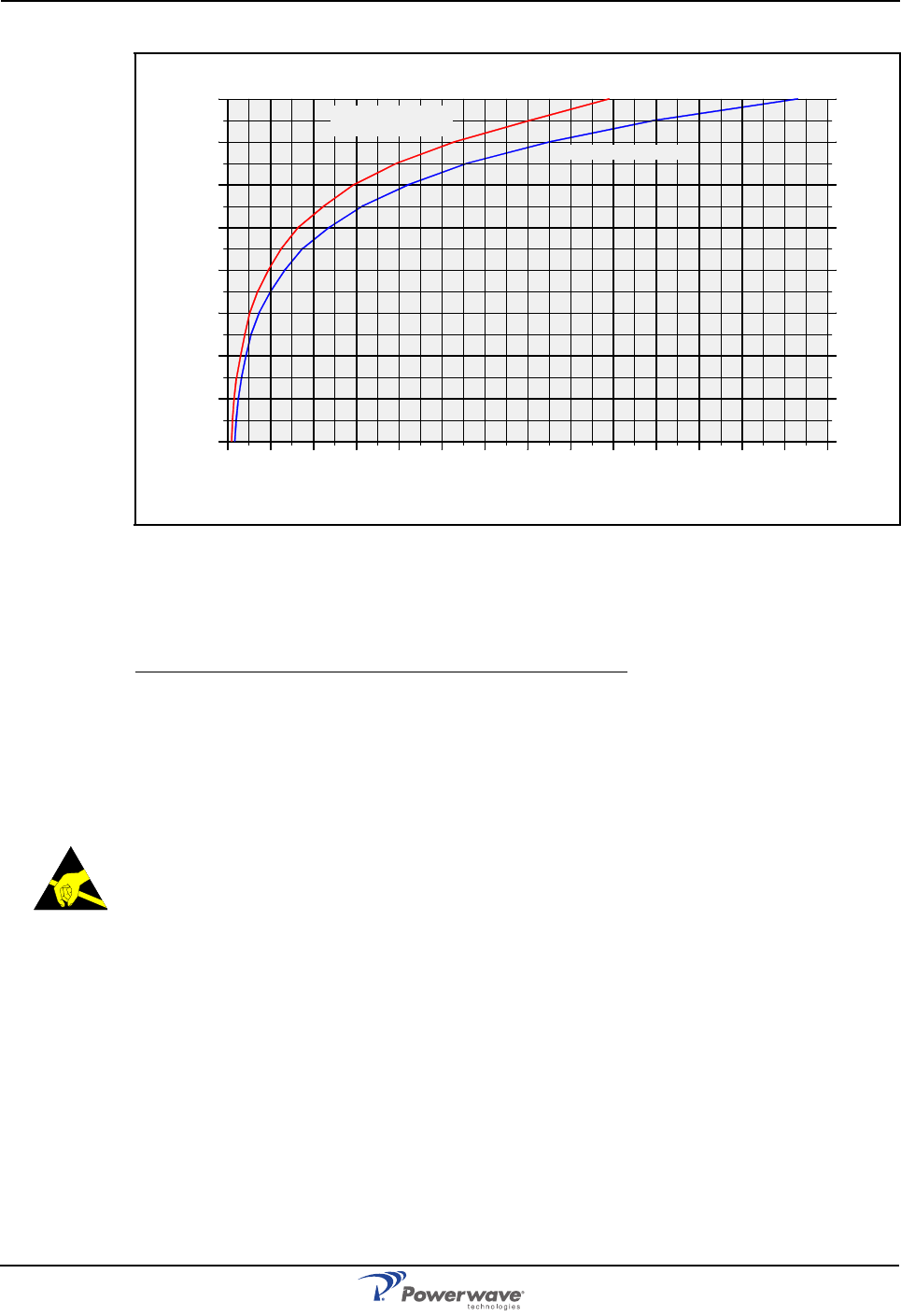
For antennas larger than 20cm the maximum radiation power can be calculated by using the
following formula:
where S = Radiation power in W/m²
P = Output power in W
r = Distance between antenna and human in meter
To tackle the worst case successfully, the calculation does not consider system power
reducing actions, such as power control and DTX. Figure 1-1 shows the safety distance to an
antenna due to the RF radiation. The distance depends on antenna output power and
frequency, which is illustrated with the two graphs. One graph applies to 4.5W/m2 (900MHz)
and the other to 9.0W/m2 (1800MHz) or 10.0W/m2 (2100MHz). The safety distance range is 0
to 1.4 meters which covers an antenna power range of 10dBm to 50dBm (0.01W to 100W).
Radiation Safety Distances
This section illustrates the safety distances to the antennas for some typical repeater
configurations.
Outdoor GSM 900MHz
The safety distance can be read to 0.75 meter in Figure 1-1 as the maximum radiation power
is 4.5W/m2 for 900MHz.
Indoor GSM 900MHz
The safety distance can be read to 0.035 meter for 4.5W/m2 (900MHz).
Outdoor UMTS Standard High Power
The safety distance can be read to 0.9 meter for 10W/m2 (2100MHz).
Repeater output power +33dBm
Feeder loss –5dB
Antenna gain +17dBi
Equivalent Isotropic Radiated Power (EIRP) +45dBm
Repeater output power +22dBm
Feeder loss –5dB
Antenna gain +1dBi
EIRP +18dBm
Repeater output power +38dBm
Feeder loss –5dB
Antenna gain +17dBi
EIRP +50dBm
SP
4πr2
××
--------------------
=
AR Standard Repeater Safety
1-4 044-05250 Rev A
Indoor UMTS
The safety distance can be read to 0.035 meter for 10W/m2 (2100MHz).
Electrostatic Discharge (ESD)
ESD can severely damage essential parts of the equipment if not handled carefully. Parts on
printed circuit board assemblies (PCBA) as well as other parts in the equipment are sensitive
to ESD. Never touch the PCBA or uninsulated conductor surfaces unless absolutely
necessary.
If you must handle the PCBAs or uninsulated conductor surfaces, use ESD protective
equipment or first touch the chassis with your hand. Never let your clothes touch PCBAs or
uninsulated conductor surfaces and always store PCBAs in ESD-safe bags.
Figure 1-1 Safety distance to active antenna.
Repeater output power +24dBm
Feeder loss –5dB
Antenna gain +3dBi
EIRP +22dBm
10
15
20
25
30
35
40
0 0.1 0.2 0.3 0.4 0.5 0.6 0.7 0.8 0.9 1.0
45
50
1.1 1.2 1.3 1.4
0.0
1
0.0
3
0.1
0.3
1.0
3.2
10.
0
31.
6
100
4.5W/m2 (900MHz)
9W/m2 (1800MHz)
10W/m2 (2100MHz)
Antenna output power in dBm
Antenna output power in W
Safety distance to antenna in meter
Overview AR Standard Repeater
044-05250 Rev A 1-5
Overview
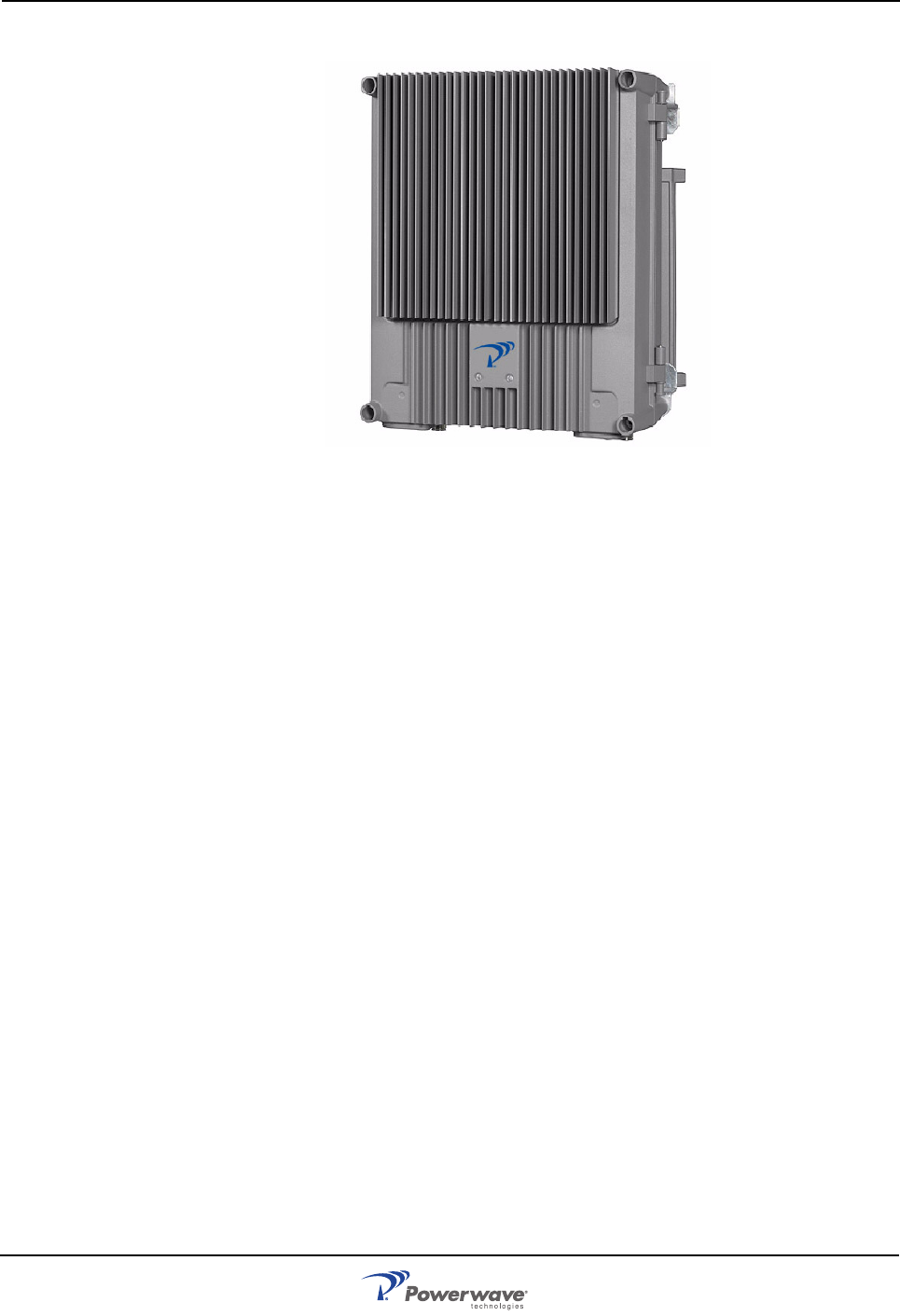
Figure 1-2 Powerwave AR Standard Repeater
Powerwave AR repeaters work as bi-directional on-frequency amplifiers used to fill out
uncovered areas in wireless mobile systems such as base station fringe areas, tunnels,
business, convention centers, airports and industrial buildings.
A repeater receives, amplifies and transmits signals to/from a base station to/from mobile
stations with both directions being served simultaneously. To be able to receive and transmit
signals in both directions, a repeater is connected to a donor antenna directed towards the
base station and to a service antenna directed towards the area to be covered. These
antennas are connected to the repeater with N type or 7/16" male connectors. The repeaters
can also be connected via RF cables or fiber optic cables instead of donor or service antennas.
Powerwave repeaters are microprocessor controlled with alarm and operational status LEDs
visible on the front cover. Cooling is provided through convection heat dissipation. To prevent
instability due to poor antenna isolation, a built-in antenna isolation supervision feature
reduces the gain level automatically when poor antenna isolation is detected.
Operational parameters, such as gain, channel number and power levels are set using a PC
running Powerwave OM-Online software which can communicate with the repeaters either
locally or remotely via modem. Remote operation can be performed via PSTN or a GSM net.
The Operation and Maintenance System (OMS) provides for Network Operations Center
(NOC) configuration and alarm montioring.
AR repeaters can be configured in many combinations, depending on the wireless system,
single or double system operation, RF or optical transmission, and output power. The most
common types of the AR repeaters are described in the following sections. Since all of the
repeater models can be configured differently, the descriptions are applicable only to a small
portion of the most commonly configured repeaters.
In this document, the channel selective 900, 1800, and 1900 systems are called GSM, DCS
and PCS respectively even though these systems may have different names in other parts of
the world.
Repeaters with RF / RF Transmission
All units depicted on this and the following pages are assumed to have the donor connection
to the left and the service connection to the right.
Channel Selective (CSel) Repeater
A channel selective GSM repeater is used for channel selective systems such as GSM, DCS,
and PCS. It can be equipped with up to four channels in a standard chassis and up to eight in

AR Standard Repeater Overview
1-6 044-05250 Rev A
a high cover chassis. This repeater type has the ability to work with GSM (GMSK) and EDGE
(8PSK) in GSM and PCS systems. AR17xx, AR27xx, and AR37xx are EDGE compatible.
A channel selective CDMA or WCDMA repeater is used for digital code division systems in
accordance with IS-95 (CDMA 2000 – 3GPP2) for CDMA and 3GPP / UMTS for WCDMA or
J-STD-008 standard, and wideband digital code division systems. It can be equipped with two
channels in the cabinet and additional two channels in a high cover. It can be connected with
either a donor antenna or RF cable and a service antenna or RF cable.
Channel selective High Power CDMA/WCDMA repeaters are the same as the CDMA/WCDMA
repeaters but are equipped with a 6dB (typically) Booster Amplifier (BA) in the downlink path.
The BA is located in the high cover with its own PSU and reduces the number of channels to
two in the cabinet.
Band Selective (BSel) Repeater
The band selective repeater has an adjustable bandwidth and is used for analog or digital
systems such as GSM, TACS, ETACS, AMPS, DAMPS, CDMA and WCDMA. This repeater
type can be equipped with one band in the cabinet and additional one band in a high cover. It
can be connected with either a donor antenna or RF cable and a service antenna or RF cable.
Repeaters with RF / Fiber Optic Transmission
Base Station Master Unit (BMU)
A BMU is equipped with a Fiber Optic Node (FON) for optical transmission on the service side.
It has an RF port for BTS connection and can provide up to four fiber optic ports that can be
connected to Fiber Optic Repeaters (FORs) and WRHs by using WDMs and splitters. FORs
and WRHs can be fed in parallel with double or single fiber optic cables. Up to eight FORs and
WRHs can be fed if the BMU is equipped with a high cover and two FONs. The BMU is also
available as a 19" rack mounted unit called an Optical Conversion Module (OCM). Information
on the OCM is located in the Fiber Optic Equipment User Manual (044-052530).
Repeater Master Unit (RMU)
An RMU is a repeater equipped with a FON for optical transmission on the service side. The
RMU has an RF port for a donor antenna and provide up to four fiber optic ports that can be
connected to FORs and WRHs by using WDMs and splitters. FORs and WRHs can be fed in
parallel with double or single fiber optic cables. Up to eight FORs and WRHs can be fed if the
BMU is equipped with a high cover and two FONs.
Repeater with Fiber Optics / RF Transmission
A FOR is a repeater equipped with a FOU for optical transmission on the donor side. The FOR
can connect to either a service antenna or RF cable. The FOR has a fiber optic donor port and
an RF port for a service antenna (or RF cable). This unit can be connected to a BMU or RMU.
Combined Repeater
Some of the repeater types mentioned above can be combined in the same repeater chassis
and be in operation in parallel. This can be used for different systems or different operators.
One repeater part is located in the cabinet and an additional repeater part is located in a high
cover. A combined repeater can, for example, have two RF ports for donor antennas (or RF
cables) and two RF ports for service antennas (or RF cables).
Repeater Chassis Design
The repeater is housed in a cast aluminium waterproof chassis, class NEMA4 / IP65 approved
for outdoor use but is also suited for indoor installations. The chassis consists of a cabinet and
a cover attached with hinges. The cabinet contains the repeater circuitry. The cover comes as
either a low or high version. The high cover can be used as an empty cover or be equipped as
a part of the repeater or an independent repeater unit. A repeater with a high cover that is
equipped as two independent repeater units (combined repeater) can, for example, be
equipped for channel selective operation in the cabinet and band selective operation in the
cover.

Sub Unit Overview AR Standard Repeater
044-05250 Rev A 1-7
Sub Unit Overview
A number of amplifier boards are individually shielded and located under a metal cover inside
the repeater. This cover can be opened outward for access. These amplifier PCBAs are of
different types depending on the supported system. All of the repeater types are built up with
a number of sub units which are described in the following paragraphs.
Channel Amplifier PCBA for GSM and EDGE (CHE)
The CHE is used for CSel operations. CSel GSM repeaters can handle up to eight channels.
For every even number of channels, two CHEs are required, one for the uplink and one for the
downlink. Numbered from left to right, positions 1 and 2 are used for two DL CHEs and 3 and
4 for two UL CHEs. Each repeater channel is allocated to a radio channel or switched off. In a
GSM system, each repeater channel can handle eight calls (sixteen if half-rate encoding is
used).
CDMA/WCDMA Segment Amplifier PCBA (CSA)
CSel CDMA/WCDMA repeaters can handle two CDMA or WCDMA repeater channels. The
CSA provides this capability. For every even number of channels, two CSAs and two PAs are
required; one pair of CSA/PAs for the uplink and one pair for the downlink. Each repeater
channel is allocated to a radio channel or switched off. Numbered from left to right, position 1
is used for a CSA, position 2 for a DL PA, position 3 for a CSA and position 4 for a UL PA.
Band Selective Amplifier PCBA (BSA)
The BSA is used for BSel operations. BSel repeaters can handle multi-carriers over a wide
band through the use of an adjustable bandwidth. Each repeater band requires two BSAs and
two PAs; one pair of BSA/PAs for the downlink and one pair for the uplink. Numbered from left
to right, position 1 is used for a DL BSA, position 2 for a DL PA, position 3 for an UL BSA and
position 4 for an UL PA.
Power Amplifier PCBA (PA)
The PA is used to amplify the output signal from a BSA and a CSA. Each PCBA contains one
path that can be used for either DL or UL amplification. Two PAs are thus required for one band
for the downlink and uplink.
Booster Amplifier (BA)
CDMA/WCDMA repeaters can be equipped with a BA on the DL path to boost the output gain
by 6dB (typically). The BA can operate with a maximum of 2 channels and occupies position
3 in the cabinet and position 7 in a high cover. It also requires an extra heat sink element on
the outside of the cabinet or high cover. Some configurations use the existing PSU while others
require a second PSU.
Distribution PCBA (DIA)
The DIA is a distribution PCBA on which all other PCBAs and units are connected to in the
cabinet. A shielded metal frame on the DIA provides the mounting location for the CU, ALI and
RCIs, if used.
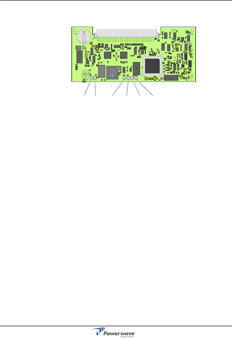
Control Unit PCBA (CU)
The CU PCBA, illustrated in Figure 1-3, is the core microprocessor controller PCBA in the AR
repeater and connects to port P2 on the DIA. It contains a microprocessor, main memory,
flash memory for the CU software, EEPROM memory for parameters, memory for the event
log and statistics, a REFO reference oscillator, ports for local and remote communication,
battery powered real-time clock, and MAC identity circuit.
The CU supervises and controls operational parameters such as gain control and channel
handling, alarms, event log, password and logon. It is also a control interface for OM-Online
and OMS. Software for the CU can be downloaded from OM-Online, either locally or remotely,
or from OMS.
AR Standard Repeater Sub Unit Overview
1-8 044-05250 Rev A
CU PCBAs from part # K103/3 handle R2R communications which means the RIA is not
required for R2R network. The CU is located in the lower right part of the shielded DIA frame.
LED indicators are described in Chapter 2.
Figure 1-3 CU PCBA
Directional Coupler (DC)
DC units are used as antenna signal directional couplers. They are located on the left and
right side in the lower part of the cabinet if a test port (TEST –30 dB) or an antenna port (MS
–20 dB) for an internal RF modem is required. Some repeater configurations lack a DC in the
DL, UL or both directions.
Low Noise Amplifier (LNA)
LNAs are used as uplink and downlink low noise branch amplifiers. They are located in the
upper part of the cabinet or in equipped high covers. LNA/UL is located to the left and LNA/DL
to the right. Some repeater configurations lack LNAs in the DL, UL or both directions.
Duplex filter (DPX)
DPXs are located on the cover plate over the amplifier boards.
Fiber Optic Unit (FOU)
The FOU is an add-on unit for the various repeater models. In the simplest form, the FOU is a
metal plate on which a FON PCBA, a DPX and fiber optic connectors are assembled. It can
also be configured with combiners, splitters and WDMs to obtain a desired combination of
several branches with double or single fiber. The FOU is used in the BMU, RMU and FOR and
is mounted on top of the cover plate in the upper part of the repeaters.
Fiber Optic Node (FON)
The FON is a bi-directional electrical/optical signal converter and a node in either a wire
network or a fiber network. It has functionality for:
• Electrical and optical signal supervision
• Internal and external alarm handling
• RS232 interface for local PC control via an O&M software (OM-Online)
• Remote control via an O&M software (OM-Online or OMS)
• Interface for RCU
• Interface for WLI, wire network
• Interface for FLI, fiber optic network
• Battery backup with charger
The FON can be installed in all Powerwave repeaters
WLI DATA POWER BOOT FAULT OPER
Sub Unit Locations AR Standard Repeater
044-05250 Rev A 1-9
Power Supply Unit (PSU)
A PSU is located in the lower center of the cabinet and, if configured, in the lower center of the
high cover.
Remote Control Unit (RCU)
The RCU is an optional communication unit for remote control of repeaters via PSTN or RF
modems. RCU types and details are described on page 4-11.
Combiner unit (CMB)
CMB combiner units are used to combine two different bands. CMB units are located on the
cover plate over the amplifier boards.
Alarm Interface PCBA (ALI) and Remote Control Interface PCBA (RCI)
The ALI handles alarms and alarm communication. It is replace with an RCI if an RCU is used
and provides an interface between the CU and an RCU for remote communication via modem.
The RCI also handles alarms and alarm communication. Either unit is located in the lower left
part of the shielded DIA frame.
Repeater-to-Repeater Interface Adapter (RIA)
The RIA is required for R2R networking if a previous CU PCBA (K103/2), is used. This PCBA
is located in the upper left part of the shielded DIA frame. R2R functionality is included starting
in the CU PCBA part # K103/3.
Sub Unit Locations
The following sections describe the sub unit locations of the different models of AR Repeater
and distribution units.
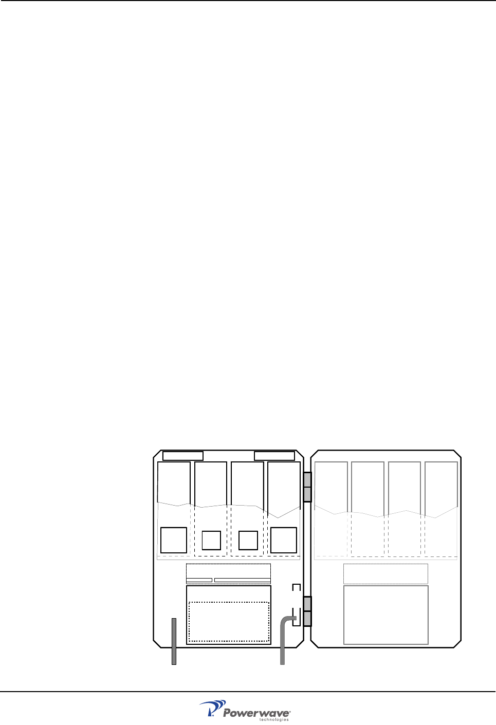
CSel GSM Repeater
A cabinet for a CSel GSM repeater can be equipped with four CHEs, two for the downlink (DL)
with two internal channels each and two for the uplink (UL) with two internal channels each.
The described cabinet has a capacity of four bi-directional GSM channels. A high cover can be
equipped as well providing up to eight GSM channels. PCBA positions are illustrated in Figure
1-4 and a block diagram is located in Appendix A.
Figure 1-4 CSel GSM Repeater Sub Unit Locations
LNA - DL
1234
LNA - UL
PSU
(RCU)
DPX
CUALI/RCI
DC
BS
DPX
CHA1
DL
2
CHA2
DL
2
CHA3
UL
2
CHA4
UL
2
CMB
DL CMB
UL
1234
CHA1
DL
2
CHA2
DL
2
CHA3
UL
2
CHA4
UL
2
5678
CHA5
DL
2
CHA6
DL
2
CHA7
UL
2
CHA8
UL
2
PSU
AR Standard Repeater Sub Unit Locations
1-10 044-05250 Rev A
CSel CDMA/WCDMA Repeater
A cabinet for a CSel CDMA or WCDMA repeater can be equipped with two pair of CSAs and
PAs, one pair for the DL and one pair for the UL. The described cabinet has a capacity of two
bi-directional CDMA or WCDMA carriers. A high cover can be equipped as well providing up
to four CDMA or WCDMA channels. PCBA positions are illustrated in Figure 1-5 and a block
diagram is located in Appendix A.
Figure 1-5 CSel CDMA/WCDMA Repeater Sub Unit Locations
CSel High Power CDMA/WCDMA Repeater
A cabinet for a CSel High Power CDMA or WCDMA repeater can be equipped with two pair of
CSAs and PAs, one pair for the DL and one pair for the UL. The described cabinet has a
capacity of two bi-directional CDMA or WCDMA carriers. A high cover is equipped with the BA
and an extra heat sink element on the outside of the cover. PCBA positions are illustrated in the
Figure 1-6 and a block diagram is located in Appendix A.
Figure 1-6 CSel High Power Repeater Sub Units Locations
LNA - DL
1234
LNA - UL
PSU
(RCU)
DPX
CUALI/RCI
DC
BS
DPX
CSA
DL
2
PA
DL CSA
UL
2
PA
UL
5678
CSA
DL
2
PA
DL CSA
UL
2
PA
UL
PSU
LNA - DL
1234
LNA - UL
PSU
(RCU)
CUALI/RCI
DC
BS
DPX
CSA
DL
2
PA
DL CSA
UL
2
PA
UL
7
BA
DL
DPX
Sub Unit Locations AR Standard Repeater
044-05250 Rev A 1-11
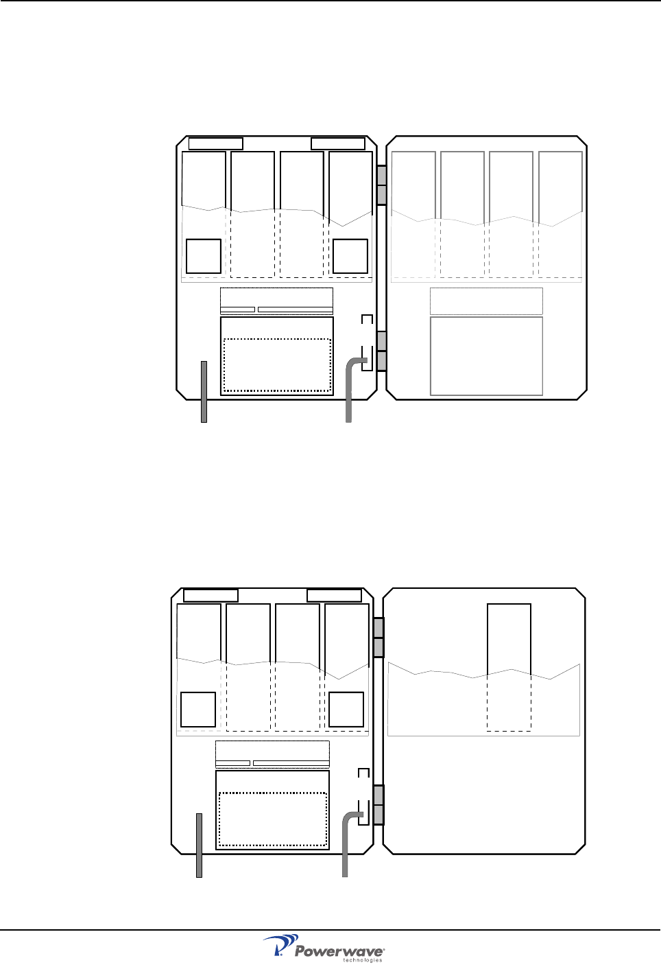
BSel Repeater
A cabinet for a band selective repeater is equipped with two pairs of BSAs and PAs, one pair
for the DL and one pair for the UL. The described cabinet is equipped for bi-directional band
selective operation. A high cover can be equipped as well providing two bands. PCBA
positions are illustrated in the Figure 1-7 and a block diagram is located in Appendix A.
Figure 1-7 BSel Repeater Sub Unit Locations
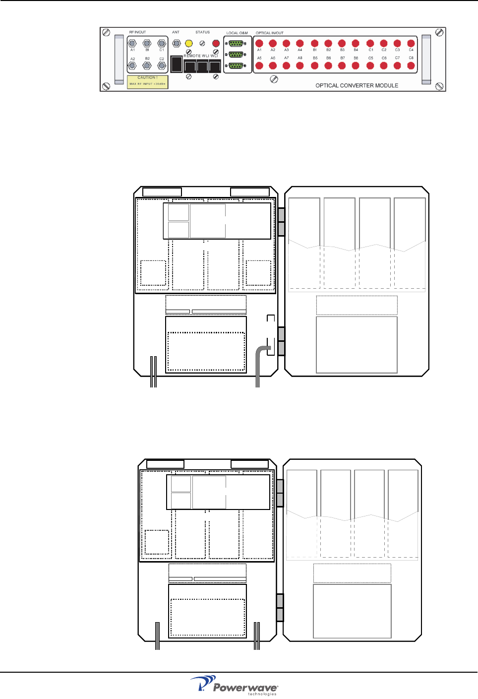
BMU
The BMU has the donor and service cable ports opposite the ports of other repeaters. A
cabinet for a BMU has no CU PCBA and no amplifier PCBAs but instead contains a FOU with
a FON and a DPX. By adding WDMs and splitters to the FOU, up to four FORs can be fed in
parallel by a BMU with double or single fiber communication. A high cover can be equipped as
well providing connections for up to eight FORs. PCBA positions are illustrated in the Figure 1-
8 and a block diagram is located in Appendix A. The most common unit used to get the BMU
functionality is the 19" indoor rack mounted OCM illustrated in Figure 1-9. The OCM is
described in the Fiber Optic Equipment Operation and Maintenance Manual.
Figure 1-8 BMU Sub Unit Locations
LNA - DL
1234
LNA - UL
PSU
(RCU)
DPX
CUALI/RCI
DC
BS
DPX
BSA
DL PA
DL BSA
UL PA
UL
5678
PSU
BSA
DL PA
DL BSA
UL PA
UL
PSU
DC
BS
FON
DPX
FOU
DPX
FON
FOU
(RCU)
AR Standard Repeater Sub Unit Locations
1-12 044-05250 Rev A
Figure 1-9 Optical Converter Module (OCM)
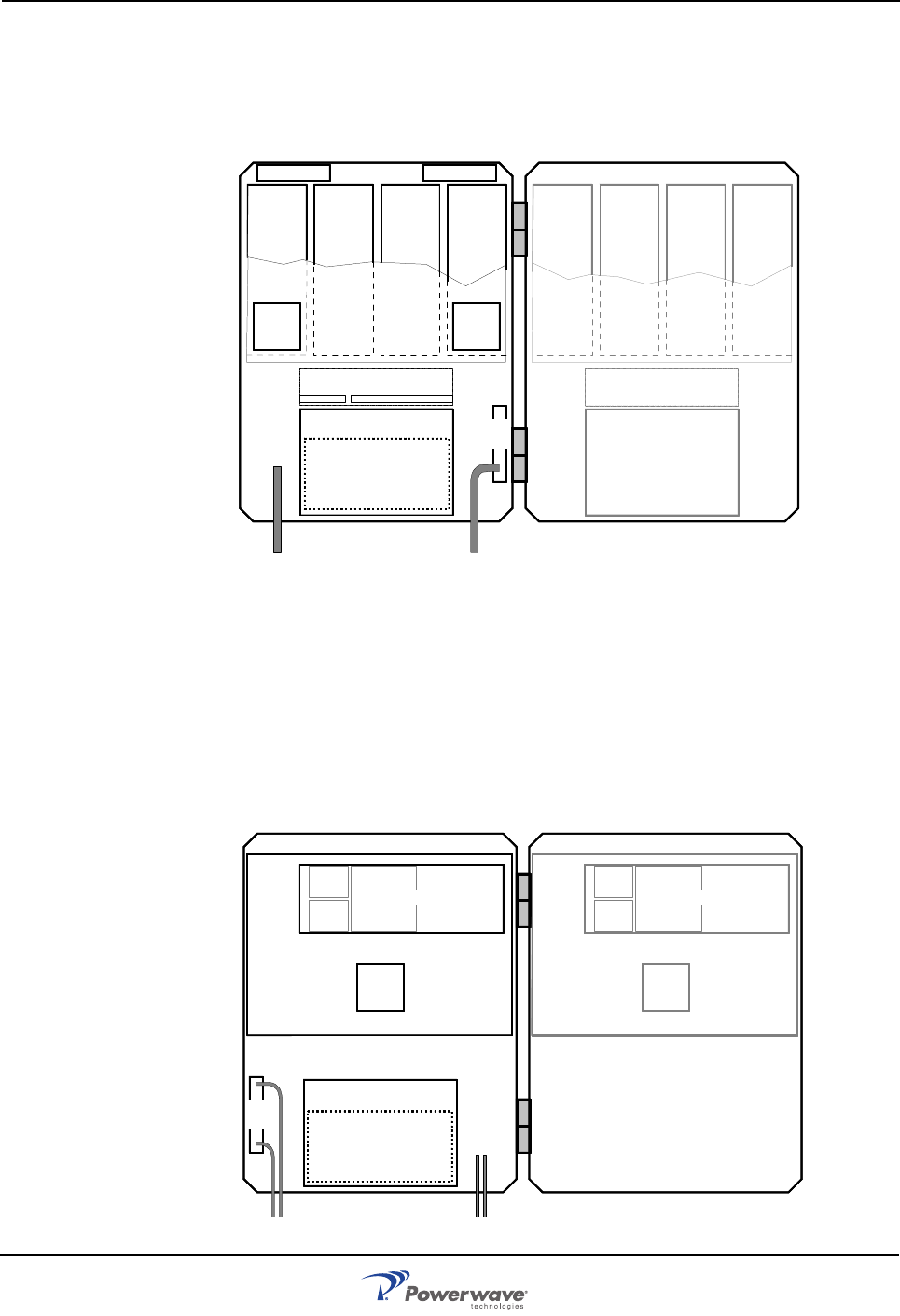
RMU
Figure 1-10 illustrates an example of an RMU for BSel operation. This unit has a FON and a
DPX. By adding WDMs and splitters to the FOU up to four FORs can be fed in parallel by a
BMU with double or single fiber communication. A block diagram is located in Appendix A.
Figure 1-10 RMU Sub Unit Locations
FOR
Figure 1-11 illustrates an example of a FOR for band selective operation. This unit has a FON
and a DPX.
Figure 1-11 FOR Sub Unit Locations
LNA - DL
1234
LNA - UL
PSU
(RCU)
DPX
CUALI/RCI
DC
BS
DPX
BSA
DL PA
DL BSA
UL PA
UL
5678
PSU
BSA
DL PA
DL BSA
UL PA
UL
FOU
FON
LNA - DL
1234
LNA - UL
PSU
(RCU)
DPX
CUALI/RCI
BSA
DL PA
DL BSA
UL PA
UL
5678
PSU
BSA
DL PA
DL BSA
UL PA
UL
FOU
FON
Using Repeaters AR Standard Repeater
044-05250 Rev A 1-13
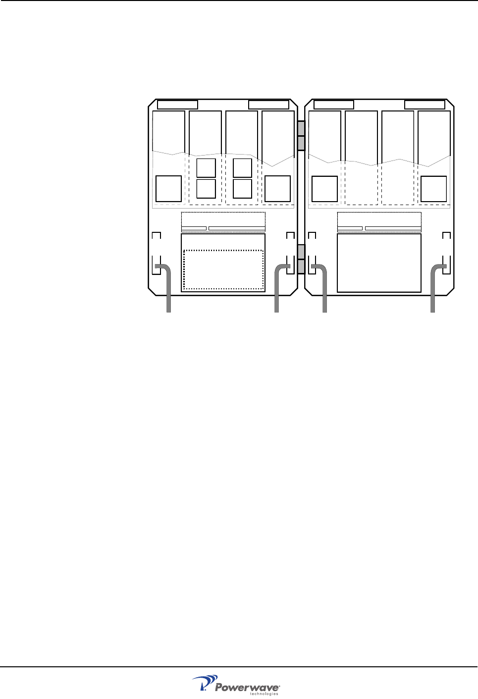
Combined Repeater
Figure 1-12 illustrates a combined CSel and BSel repeater. The CSel part is located in the
cabinet and the BSel part in a high cover. This example has four bi-directional GSM channels
and BSel operation. Most of the repeater models mentioned in this manual can be mixed as a
combined repeater.
Figure 1-12 Combined Repeater Sub Unit Locations
Using Repeaters
In areas where the radio signal propagation is poor, repeaters can be used to fill out those
areas which are not covered by the base station. Examples include:
• Sports arenas
•Fair halls
• Large shopping centres
• Road and railway tunnels
• Indoors in buildings with metal or concrete walls
• Other examples where repeaters can be used to increase the coverage are:
• Shaded areas
• Fringe coverage areas
In areas where the traffic intensity is low it is not cost efficient to install a base station, so the
use of a repeater is a better, more cost effective oprion.Two examples are described in the
following paragraphs: a shaded valley and an indoor sports arena.
LNA - DL
1234
LNA - UL
PSU
(RCU)
DPX
CU
ALI/RCI
DC
MS DC
BS
DPX
CHA1
DL
2
CHA2
DL
2
CHA3
UL
2
CHA4
UL
2
1234
PSU
BSA
DL PA
DL BSA
UL PA
UL
DC
MS DC
BS
DPX DPX
CMB
DL
LNA - DLLNA - UL
CMB
DL
CMB
UL
CMB
UL
CU
ALI/RCI
AR Standard Repeater Using Repeaters
1-14 044-05250 Rev A
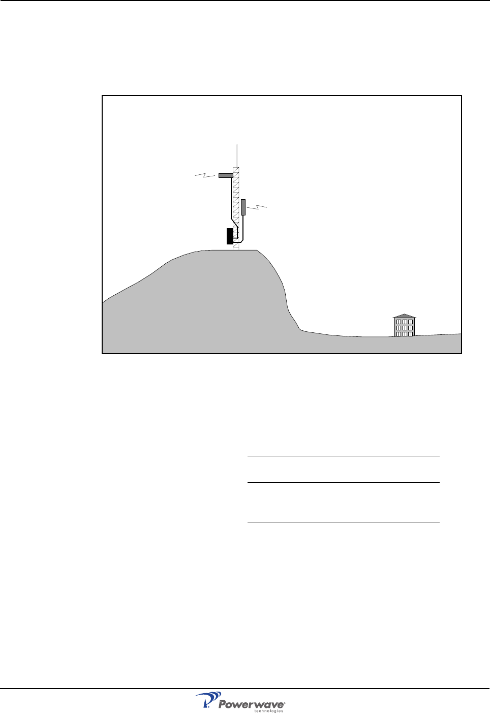
Shaded Area
In this example, we have a valley that is shaded by the hills surrounding it. There is a base
station 5 kilometers away but the lowest signal strength in the valley is less than –100dBm. A
42 meter mast used for other purposes is located on one of the hills and is available for a
repeater installation as illustrated in Figure 1-12.
The donor antenna was mounted at the top of the mast and the service antenna was mounted
at half mast on the other side. Antenna isolation was measured to over 100dB and the repeater
was set to 80dB gain.
The measured result in the valley was better than –90dBm.
Figure 1-13 Repeater coverage of shaded area.
Measured levels: Received signal level – 60.0 dBm
Donor antenna gain 15.0 dBi
Cable loss – 5.0 dB
Repeater input level –50.0 dBm
Adjusted repeater gain 70.0 dB
Repeater output level 20.0 dBm
Cable loss – 5.0 dB
Service antenna gain 8.0 dBi
Radiated output level 23.0 dBm
Donor antenna
Service antenna
Using Repeaters AR Standard Repeater
044-05250 Rev A 1-15
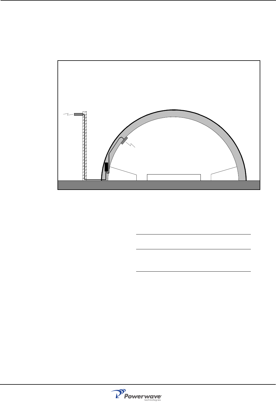
Sports Arena
In this example, we have a 2000 spectator sports arena with a metallic roof that had an indoor
signal strength too low to provide fair service in most parts of the arena. The nearest base
station was 8 kilometers away and was equipped with only one carrier. A donor antenna
directed towards the BTS was mounted on a mast outside the building and a repeater was
installed inside the building with the service antenna on the ceiling as illustrated in Figure 1-14.
The antenna isolation was measured to over 85dB.
The signal strength was fair for service in the entire arena.
Figure 1-14 Repeater in sports arena.
Measured levels: Received signal level – 80.0 dBm
Donor antenna gain 15.0 dBi
Cable loss – 5.0 dB
Repeater input level – 70.0 dBm
Adjusted repeater gain 75.0 dB
Repeater output level 5.0 dBm
Cable loss – 2.0 dB
Service antenna gain 7.0 dBi
Radiated output level 10.0 dBm
Donor antenna
Service antenna
AR Standard Repeater Using Repeaters
1-16 044-05250 Rev A
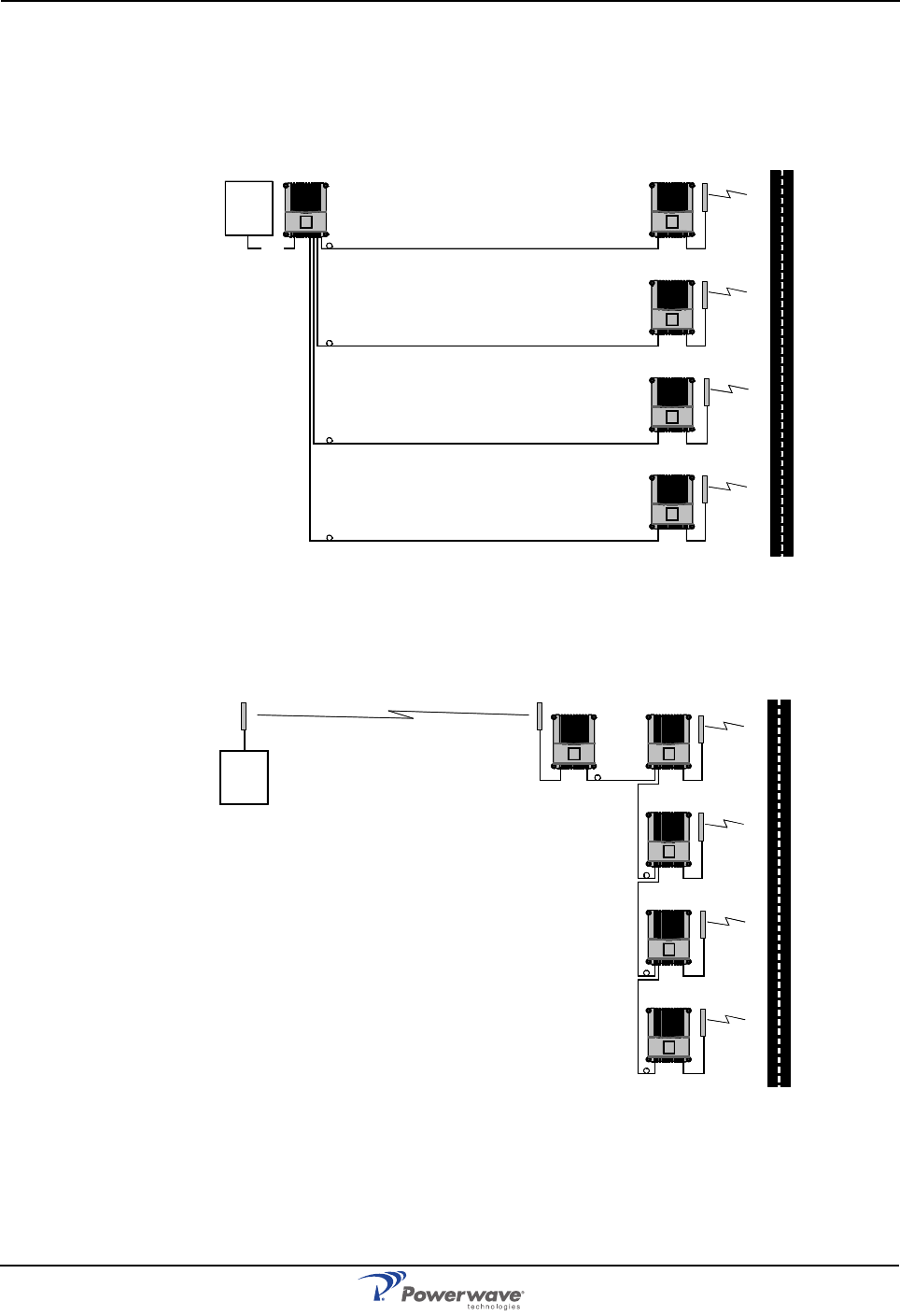
Fiber Optic Distribution Networks
Fiber optic networks are setup identically to data networks by using either a star or daisy-chain
configuration. The two examples below illustrate part of a road covered by a BMU or RMU and
four FORs. Figure 1-15 illustrates a star configuration where a BMU is fed by a BTS via an RF
cable and four fiber optic ports that feed four FORs. The BMU has to be located very close to
the BTS.
Figure 1-15 Star Configuration Using One BMU and Four FORs
Figure 1-16 illustrates a daisy-chain configuration where a RMU with a donor antenna and one
fiber optic port feeds four FORs.
Figure 1-16 Daisy-chain Configuration Using One RMU and Four FORs
By using WDMs and OSPs in the FORs, the distribution net can be built up with a combination
of star and daisy-chain connections using double or single fiber.
BMU FOR
FOR
FOR
FOR
BTS
RF
RMU FOR
FOR
FOR
FOR
BTS
Using Repeaters AR Standard Repeater
044-05250 Rev A 1-17
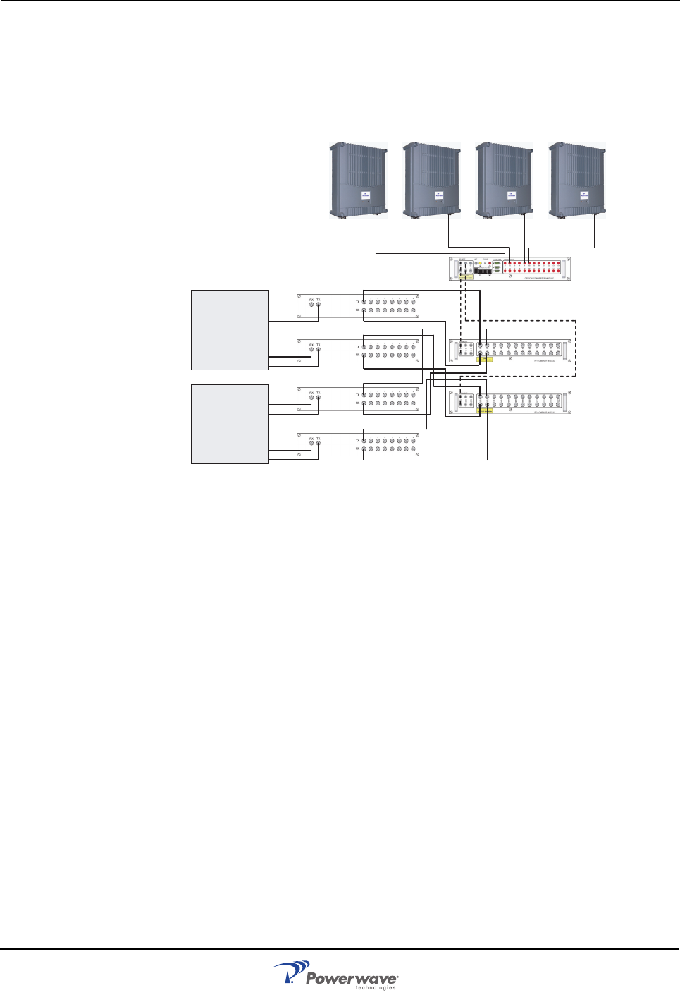
Multi-Operator Configurations
Multi-operator systems require the use of Point of Interconnects (POIs), RF Combining
Modules (RCMs) and OCMs as illustrated in Figure 1-17. In this simple example, two operators
have two sectors each. Each sector is connected to a POI and then to a RCM. The RCM is
interconnected with an OCM via coaxial cables. The combined DL and UL signals are
converted to optical signals in the OCM and then distributed to the ARs.
Figure 1-17 Multi-operator System
The example illustrates a star networking connection. The ARs could also be connected in a
daisy-chain configuration using splitters. The complete system is properly tuned during
commissioning. Additional information is provided in the Fiber Optic Equipment Operation and
Maintenance Manual.
O
p
erator 1
O
p
erator 2
Sector 1
Sector 1
Sector 2
Sector 2
OCM
RCM
RCM
POI
POI
POI
POI

AR Standard Repeater Using Repeaters
1-18 044-05250 Rev A
This Page Intentionally Left Blank
044-05250 Rev A 2-1
Chapter 2
Controls, Connections and Indicators
Introduction
This chapter contains descriptions of the controls, connections and indicators of the AR
Standard Repeater.
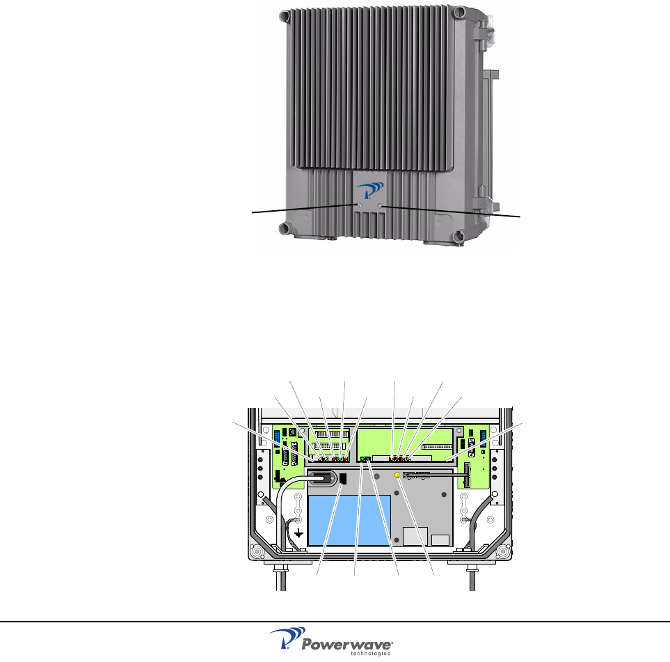
Front Cover LED Indicators
Two LEDs are located on the front cover to provide easy identification of a fault in the
repeater system. The amber operation LED lights up approximately 15 seconds after the
main power is switched on. When the LED is steady, the repeater is ready for operation. The
red Alarm LED indicates system error alarms when flashing and a critical alarm when steady.
Figure 2-1 External indicators
Cabinet LED Indicators
Figure 2-2 illustrates and Table 2-1 describes the LED indicators located on the ALI, or RCI,
and CU PCBAs. This is not applicable to the BMU which uses the LED indicators located on
the FON. These indicators are described in further detail in the following sections.
Figure 2-2 Cabinet Internal Indicators
Amber Red
MS
DPX
ANT
TEST
DC
-30 dB
-20 dB MS
DPX
ANT
TEST
DC
-30 dB
-20 dB
ALLGON INNOVATION
SWE DEN M 105 R6
1
PARKING
FOR W5
W5
8
P27 W6B 10
1
P33
ALARM
P23
LNA
UP-L I NK
P32
MODEM
AUX1
P28
DOOR
5
9
61
116
1
1
M->S
P11
P34
8
9
15
P26
15 16
S->M
12
389
P36
5
X0A
X0B
2V2 116
P12 P13
1
1
1
16
16
16
P4
P5
P6
c
b
a
c
b
a
c
b
a
c
b
a
1P232
1
b
a
116P3
16 116
P14
1
V1
1
1
1
1
1
4
6
1
15
6
915
2
16
1
2
4
5
8
5
P35
P21
PSU
6
10
P31
PC
P29
P24
P25
GND
7
6V6
LNA
DOWN-LINK
LED
P22
1
2
POWER SUPPLY UNIT
C
U
ALI
or
RCI
SV
OPER
FAULT
POWER
10V ALARM
POWER
BOOT
FAULT
OPER
WLI / R2R DATA
AR Standard Repeater PCBA Connections
2-2 044-05250 Rev A
Table 2-1 LED Indicators
PCBA Connections
This following paragraphs describe the connectors on the main PCBAs inside the AR
repeater.
CHE PCBA
Table 2-2 lists the connectors and connections for the CHE PCBA. Coaxial connector P101 is
the input port and coxial connector P701 is the output port. The output signal from this port is
fed to the duplex filter either directly or via a combiner depending on the repeater
configuration.
Table 2-2 CHE PCBA Connections
LED Description
ALI or RCI PCBA
10V Green LED, indicates 10V power is available and within specification
POWER Yellow LED, indicates power is present and remains steady after power is
switched on.
FAULT Red LED, flashes for 15 – 20 seconds after main power is switched on.
Flashes for less serious alarms (Error) and is ON steady for fatal alarms
(Critical).
OPER Green LED, ON steady indicates repeater is ready for operation.
ALARM Red LED, indicates a failure within the repeater.
CU PCBA
WLI/R2R WLI wire network (IP). A flashing green LED indicates the unit is receiving
data over the subcarrier. A steady green LED indicates: the unit is currently
not receiving any data, is currently not a control station or there is no other
node in the network.
DATA Blue LED indicating data transmission in the W-net.
POWER Yellow LED indicating present power and remains steady after power is
switched on.
BOOT Steady red LED when the CU boots (10 – 15 seconds after main power is
switched on), then flashing red (5 – 10 seconds), then off if no error is
detected. If an error is detected LED will stay on.
FAULT Flashing red LED for 15 – 20 seconds after main power is switched on.
Flashes for less serious alarms (Error) and is on solid for fatal alarms (Crit-
ical).
OPER Steady green LED indicates repeater is ready for operation.
Port Connected to
CHE1/DL (position 1 from left)
P101 OUT2 on the LNA/DL low noise amplifier
P701 4 channels: Input on the CMB/DL combiner
2 channels: HI on the service DPX duplex filter
CHE2/DL (position 2 from left)
P101 OUT1 on the LNA/DL low noise amplifier
PCBA Connections AR Standard Repeater
044-05250 Rev A 2-3
CSA PCBA
Table 2-3 lists the connectors and connections for the CSA PCABA. Coaxial connector P101
is the input port and coaxial connector P301 is the output port. The signal from this port is fed
to the PA input port P4. The PA output port P5 is connected to the duplex filter of the same
path direction.
Table 2-3 CSA PCBA Connections
P701 Input on the CMB/DL combiner
CHE3/UL (position 3 from left)
P101 OUT1 on the LNA/UL low noise amplifier
P701 4 channels: Input on the CMB/UL combiner
2 channels: LO on the service DPX duplex filter
CHE4/UL (position 4 from left)
P101 OUT2 on the LNA/UL low noise amplifier
P701 Input on the CMB/UL combiner
WARNING: The CHE PCBA has power transistors which may contain beryllium oxide
(BeO) that is poisinous. Refer to the Safety section located in Chapter 1.
Port Connected to
CSA/DL (position 1 from left)
P101 OUT1 on the LNA/DL low noise amplifier
P301 P4 on the PA/DL PCBA
PA/DL (position 2 from left)
P4 P301 on the CSA/DL PCBA
P5 For the channel selective high power CDMA/WCDMA repeater: P3 on the BA/
DL PCBA
For all other models: HI on the service DPX duplex filter
CSA/UL (position 3 from left)
P101 OUT1 on the LNA/UL low noise amplifier
P301 P4 on the PA/UL PCBA
PA/UL (position 4 from left)
P4 P301 on the CSA/UL PCBA
P5 LO on the donor DPX duplex filter
AR Standard Repeater PCBA Connections
2-4 044-05250 Rev A
BSA PCBA
Table 2-4 lists the connectors and connections for the BSA PCABA. Coaxial connector P101
is the input port and coaxial connector P301 is the output port. The signal from this port is fed
to the PA input port P4. The PA output port P5 is connected to the duplex filter of the same
path direction.
Table 2-4 BSA PCBA Connections
PA PCBA
Coaxial connector P4 is the input port and coaxial connector P5 is the output port. PA output
port P5 is connected to the DPX of the same path direction.
BA PCBA
Table 2-5 lists the connectors and connections for the BA PCABA. Coaxial connector P3 is
the input port (fed by the DL PA) and coaxial connector P4 is the output port. The signal from
this output is fed, via the DL DPX and DC, to the DL antenna.
Table 2-5 BA PCBA Connections
Port Connected to
BSA/DL (position 1 from left)
P101 OUT1 on the LNA/DL low noise amplifier
P301 P4 on the PA/DL PCBA
PA/DL (position 2 from left)
P4 P301 on the BSA/DL PCBA
P5 HI on the service DPX duplex filter
BSA/UL (position 3 from left)
P101 OUT1 on the LNA/UL low noise amplifier
P301 P4 on the PA/UL PCBA
PA/UL (position 4 from left)
P4 P301 on the BSA/UL PCBA
P5 LO on the donor DPX duplex filter
WARNING: The PA PCBA has power transistors which may contain beryllium oxide
(BeO) that is poisinous. Refer to the Safety section located in Chapter 1.
Port Connected to
P3 P5 on the PA/DL PCBA
P4 HI on the service DPX
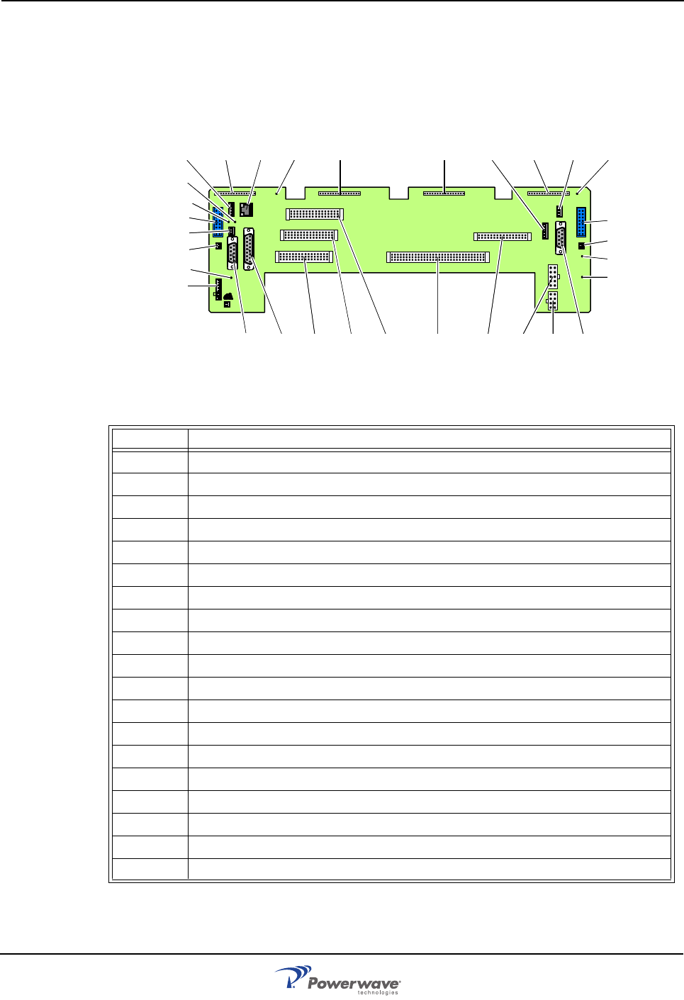
PCBA Connections AR Standard Repeater
044-05250 Rev A 2-5
DIA – Distribution PCBA
The DIA is exclusively equipped with connectors and provides signal distribution for most of
the PCBAs, units and ports in the repeater. Pins 2 and 3 on connector P27 must be
interconnected with a jumper if the connector is not used. Figure 2-3 illustrates the DIA and
Table 2-6 lists the connectors and connections.
Figure 2-3 DIA PCBA connectors and testpoints
Table 2-6 DIA PCBA Connections
Port Connected to
P2 CU PCBA
P3, 5, 6 Not Used
P4 ALI or RCI PCBA
P11 - 14 Channel PCBA positions 1 through 4
P21 PSU, connector 1
P22 LED PCBA in cover
P23 LNA/UL
P24 LNA/DL
P25 Expansion output port to cover circuitry. Only in cabinets.
P26 Expansion input port to cover circuitry. Used in equipped high covers.
P27 AUX1
P28 Door switch
P29 Power to FON
P31 PC RS-232
P32 Modem RS-232
P33 External Alarm
P34 WLI for IP or R2R network
P35 PSU, connector 2
P36 WLI for IP or R2R network
ALLGON INNOVATION
SWEDEN M105 R6
1
PARKING
FOR W5
W5
8
P27 W6B 10
1
P33
ALARM
P23
LNA
UP-LINK
P32
MODEM
AUX1
P28
DOOR
5
9
61
116
1
1
M->S
P11
P34
8
9
15
P26
15 16
S->M
12
389
P36
5
X0A
X0B
2
V2 116
P12 P13
1
1
1
16
16
16
P4
P5
P6
c
b
a
c
b
a
c
b
a
c
b
a
1P232
1
b
a
116P3
16 116
P14
1
V1
1
1
1
1
1
4
6
1
15
6
915
2
16
1
2
4
5
8
5
P35
P21
PSU
6
10
P31
PC
P29
P24
P25
GND
7
6V6
LNA
DOWN-LINK
LED
P22
1
2
V6B
P27
P26
P23
XOA
XOB
P28
P4 P5 P6 P2 P3 P31 P21 P35 P33
P32
P11 P12 P13 V1P14 P22P29P34 V2P36
V6
GND
P25
P24
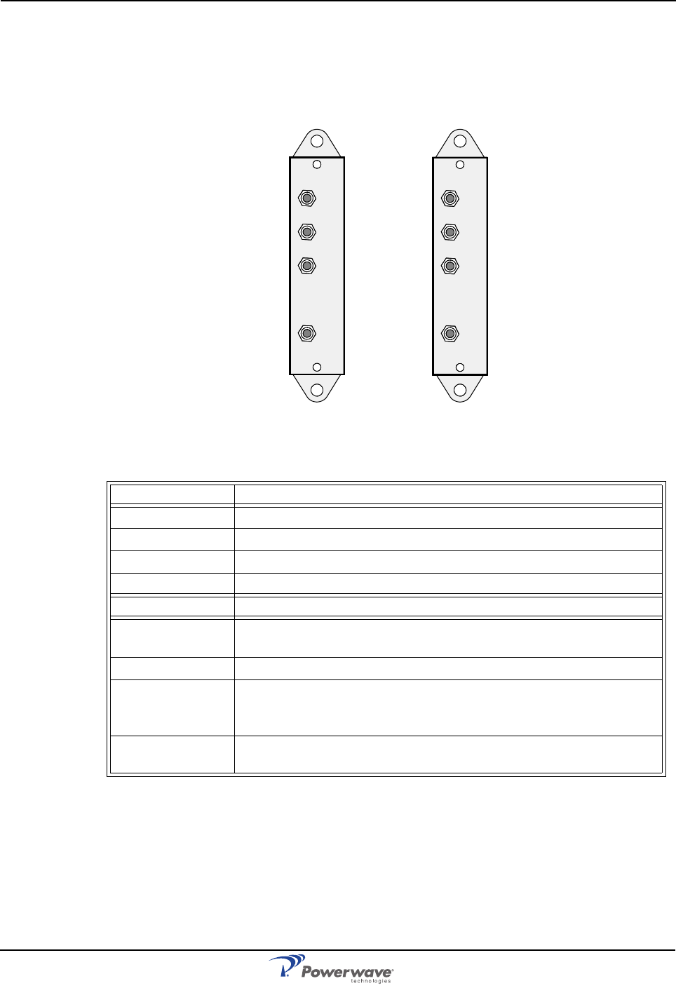
AR Standard Repeater PCBA Connections
2-6 044-05250 Rev A
DC
The DCs are located on the left and right side in the lower part of the cabinet if a test port
(TEST –30 dB) or an antenna port (MS –20 dB) for an internal RF modem is required. Figure
2-4 illustrates the DC and Table 2-7 lists the connectors and connections.
Figure 2-4 Directional Couplers
Table 2-7 Directional Coupler Connections
Service DC Port Connected to
DPX ANT on the service DPX filter
TEST -30dB Test port for the downlink output signal (no directivity)
MS -20dB Not used
ANT Service antenna or RF service cable
Donor DC Port Connected to
DPX BMU: BTS antenna
All other types: ANT on the donor DPX duplex filter
TEST -30dB Test port for the uplink output signal (no directivity)
BS -20dB BMU: ANT on the FOU/DPX filter
All other types: Antenna connection for remote control RF modem.
This port has at least 20dB directivity towards the antenna.
ANT BMU: BTS antenna output port.
All other types: Donor antenna (or RF cable to BTS).
MS
DPX
ANT
TEST
DC
-30 dB
-20 dB BS
DPX
ANT
TEST
DC
-30 dB
-20 dB
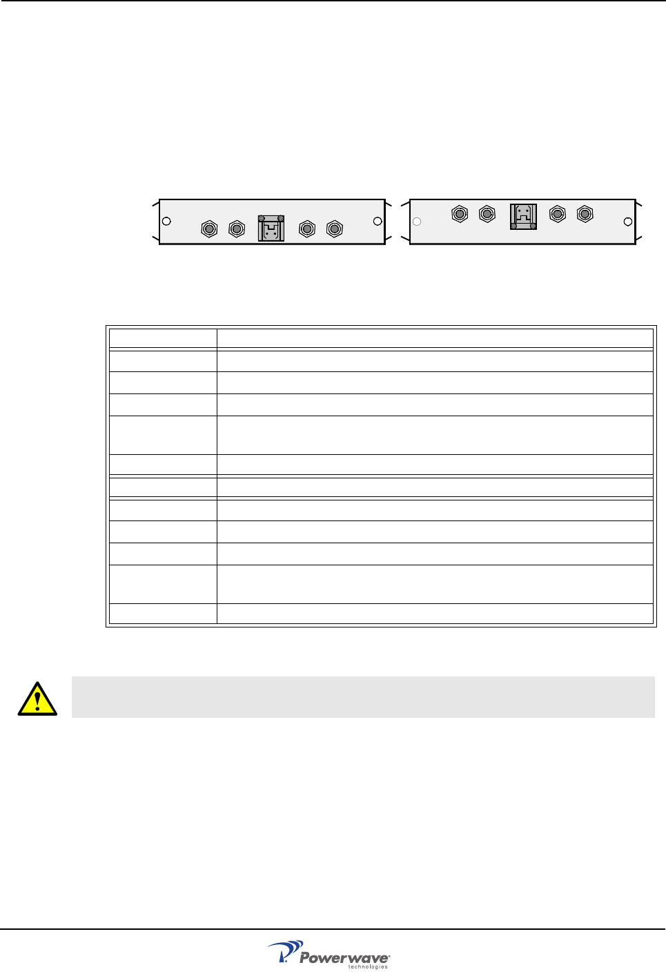
PCBA Connections AR Standard Repeater
044-05250 Rev A 2-7
LNA
Figure 2-5 illustrates the LNA and Table 2-8 lists the connectors and connections. All coaxial
connectors are SMA-type. Signals from the DPX output are fed to the LNA input connector
IN. OUT1 and OUT2 outputs feed the CHE, CSA or BSA of the same signal direction.
The signal level in these connectors are +20dB referenced to the antenna input. OUT LOW is
an expansion output for an additional LNA if the repeater is equipped in a high cover. The
gain to this connector is +2dB. The +7V input is used for +7V supply from the DIA PCBA and
ATT is a control signal for a controllable attenuator in the LNA.
Figure 2-5 Low Noise Amplifiers
Table 2-8 Low Noise Amplifier Connections
Not used outputs do not need to be terminated.
LNA/UL Port Connected to
OUT LOW IN on the LNA/UL in the cover, if equipped
IN LO on the service DPX duplex filter.
ATT +7V P23 on the DIA PCBA.
OUT1 P101 on the CHE3/UL, CSA/UL, or BSA/UL PCBA. P2101 on the
WBA PCBA.
OUT2 P101 on the CHE4/UL channel PCBA.
LNA/DL Port Connected to
OUT LOW IN on the LNA/DL in the cover, if equipped
IN HI on the donor DPX duplex filter.
ATT +7V P24 on the DIA PCBA.
OUT1 P101 on the CHE2/DL, CSA/DL, or BSA/DL PCBA. P2102 on the
WBA PCBA.
OUT2 P101 on the CHE1/DL channel PCBA.
WARNING: Some LNA power transistors may contain beryllium oxide (BeO) that is poi-
sonous. Refer to the Safety section in Chapter 1
OUT
LOW
IN+7V ATTOUT1 OUT2
LNA
DL
OUT
LOW IN ATT +7V OUT2 OUT1
LNA
UL
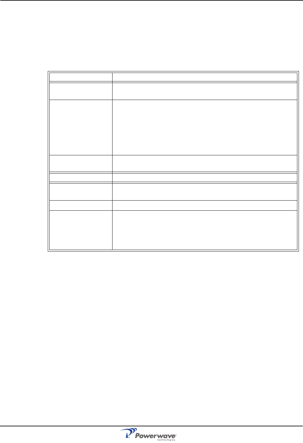
AR Standard Repeater PCBA Connections
2-8 044-05250 Rev A
DPX
DPXs are located on the metal cover sheet in the upper part of the cabinet. Service and
donor filters are identical. A DPX filter is also included in the FOU. This filter can be
connected to various ports depending on the repeater type. Table 2-9 lists the connectors and
connections of the DPX.
Table 2-9 DPX Connections
Service DPX Port Connected to
ANT RMU: ANT on the FOU/DPX filter
All other types: Service antenna (or DPX on the service (MS) DC
HI CSel GSM repeater: 4 channels: Output on the CMB/DL
2 channels: P701 on the CHE1/DL
CSel CDMA/WCDMA and BSel repeaters: P5 on the PA/DL
High power CDMA/WCDMA repeater: P4 on the BA/DL PCBA in
the cover
LO IN on the LNA/UL
P2101 on the WBA PCBA
Donor DPX Port Connected to
ANT FOR: ANT on the FOU/DPX filter.
All other types: DPX on the donor (BS) DC
HI IN on the LNA/DL
LO CSel GSM repeater: 4 channels: Output on the CMB/UL
2 channels: P701 on the CHE3/UL
CSel CDMA/WCDMA, High power CDMA/WCDMA and BSel
repeaters: P5 on the PA/UL
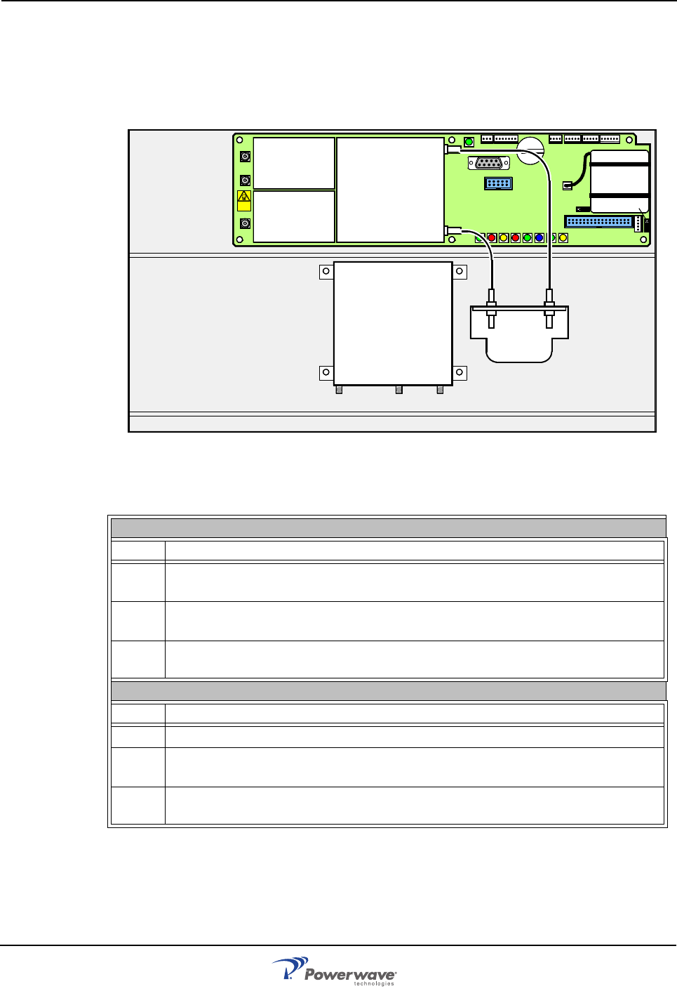
PCBA Connections AR Standard Repeater
044-05250 Rev A 2-9
FOU
FOU connections depend on the repeater type and if the FOU is connected to the donor or
service side. The RF connections for the FOU and the DPX used on the RF side are
illustrated in Figure 2-6 and listed in Table 2-10.
Figure 2-6 FOU
Table 2-10 FOU/DPX connections
on the donor side (BMU or RMU)
Port Connected to
ANT BMU: BS -20dB on the donor (BS) DC
RMU: DPX on the donor (BS) DC
HI BMU: P101 on the FON (or a CMB or CMD)
RMU: IN on the LNA/DL
LO BMU: P102 on the FON (or a CMB or CMD)
RMU: P5 on the PA/UL
on the service side (FOR and WRH)
Port Connected to
ANT Service antenna
HI FOR: P5 on the PA/DL
WRH: P5 on the PA/DL or P4 on the BA
LO FOR: IN on the LNA/UL
WRH: IN on the LNA/UL or P2 101 on the WBA
P102
P130
Beryllium
oxide
hazard
P103
P101
P114
P108P116P111
P105P109P115
P106
P104
RX
TX
P113
P112
P110
FON
DPX
ANTLO HI
P102
P101
FOU
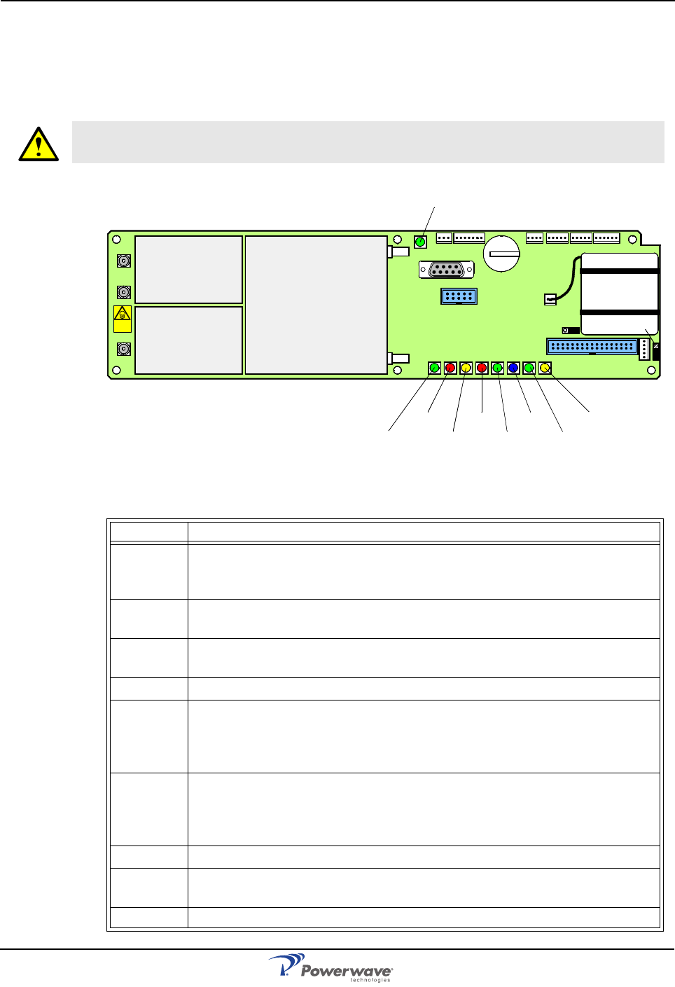
AR Standard Repeater PCBA Connections
2-10 044-05250 Rev A
FON
The FON is illustrated in Figure 2-7 and the LED indicators are described in Table 2-11. The
FON has three coaxial ports and two optical ports for the downlink and uplink RF signal. Table
2-12 defines the port numbers, connector types, and port usage.
Figure 2-7 FON LED Indicators
Table 2-11 FON LED Indications
WARNING: There are two attenuators at the P101 port on the FON that may contain
Beryllium oxide (BeO), which is poisonous. The attenuators are found inside the shield.
LED Description
FLI or
F2F Green LED. When flashing, indicates the unit is receiving data over the
sub carrier. A steady LED indicates a sub carrier is detected but the unit is
not receiving any data or there is no other node in the network.
OPER Green LED. Lights up for approximately 15 seconds after the mains is
switched on. When ON steady, indicates the unit is ready for operation.
FAULT Red LED. Flashes for 15 – 20 seconds after the mains is switched on. Will
flash for less serious alarms and be steady for fatal alarms.
POWER Yellow LED. Indicates power is present
BOOT Red LED. Will be ON steady when the control unit boots up (10 – 15 sec-
onds after the mains is switched on). Enters a flashing state next for 5 – 10
seconds. If no error is detected, the LED is off. If an error occurs, the LED
remains on.
WLI Green LED. When flashing indicates unit is receiving data over the sub-
carrier. A steady LED indicates one of the following: The unit is not cur-
rently receiving any data, the unit is not currently a control station or there
is no other node in the network.
DATA Blue LED. Indicates data transmission in the W-net
BATT Green LED. ON steady indicates battery pack is currently used as power
source.
CHARGE Yellow LED. ON steady indicates battery charging
P102
P130
Beryllium
oxide
hazard
P103
P101
P114
P108P116P111
P105P109P115
P106
P104
RX
TX
P113
P112
P110
OPER
FAULT
POWER
BOOT
WLI/R2R
DATA
BATT
CHARGE
FLI
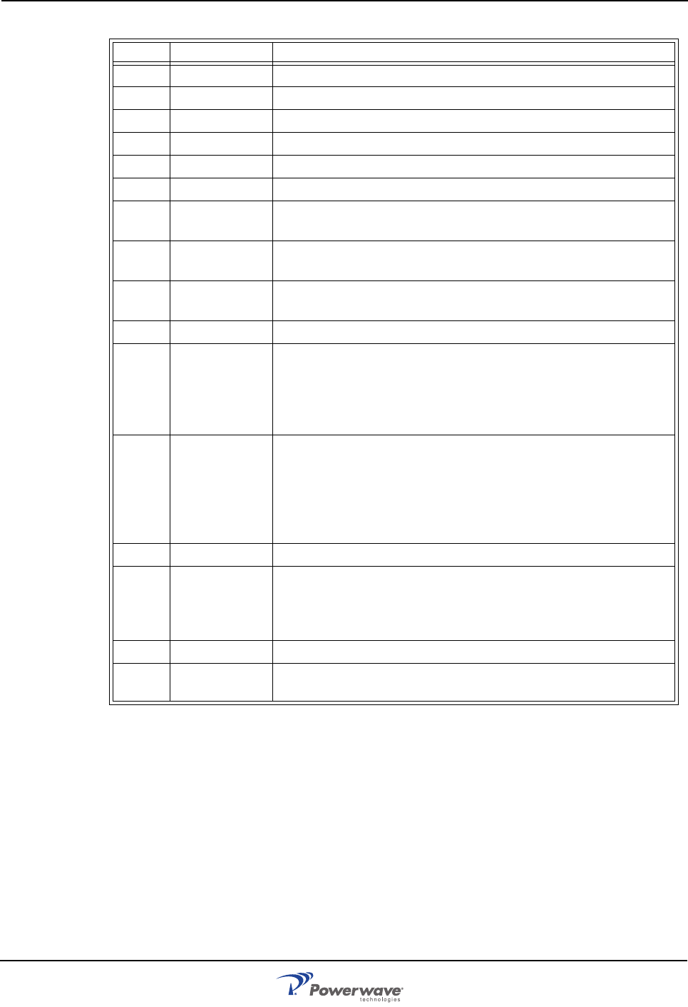
PCBA Connections AR Standard Repeater
044-05250 Rev A 2-11
Table 2-12 FON Connectors
Port Type Description
P101 SMA Electrical RF input port (to the optical TX port)
P102 SMA Electrical RF output port (from the optical RX port)
P103 SMA Electrical RF output port (15dB below the P102 port)
RX DIN/APC Optical input port (to the P102 and P103 RF ports)
TX DIN/APC Optical output port (from the P101 RF port)
P104 Used only for development and debugging
P105 4 pin male Door LED indicators. Used for the yellow and red LED indica-
tors located on the front cabinet door
P106 9 pin D-sub
female RS-232 used for local PC communication
P108
P116 6 pin male Parallel connected power ports for the FON
P109 7 pin male Used for external alarm sensors
P110 W-link
jumper Used to terminate units in a W-link. It has to be set in the
parking state for all units except for the first and last units in a
W-link. The Parking state (P) has the jumper between the
center and bottom pins. The opposite state (T) terminates the
W-link.
P111
P112 5 pin male WLI ports used for interconnecting nodes in WLI-nets (IP or
R2R networks). They are identical and connected in parallel.
One of the connectors are intended to be used from the previ-
ous node and the other connector to the next node in the net-
work. Either can be used for the first and last unit in the net
chain.
P113 2 pin male Batteries - used for the on-PCBA backup batteries.
P114 Backup
power out-
put jumper
Sets the backup power output state. The OFF state has
jumper between the center and left pins. This jumper has to
be in the OFF state when used in an OCM. Otherwise, it shall
be in the ON state.
P115 3 pin male Future port - intended for future use
P130 34 pin, 2 line
male RCU port used for connecting an RCU. The connector con-
tains both the modem connection and RCU power supply.
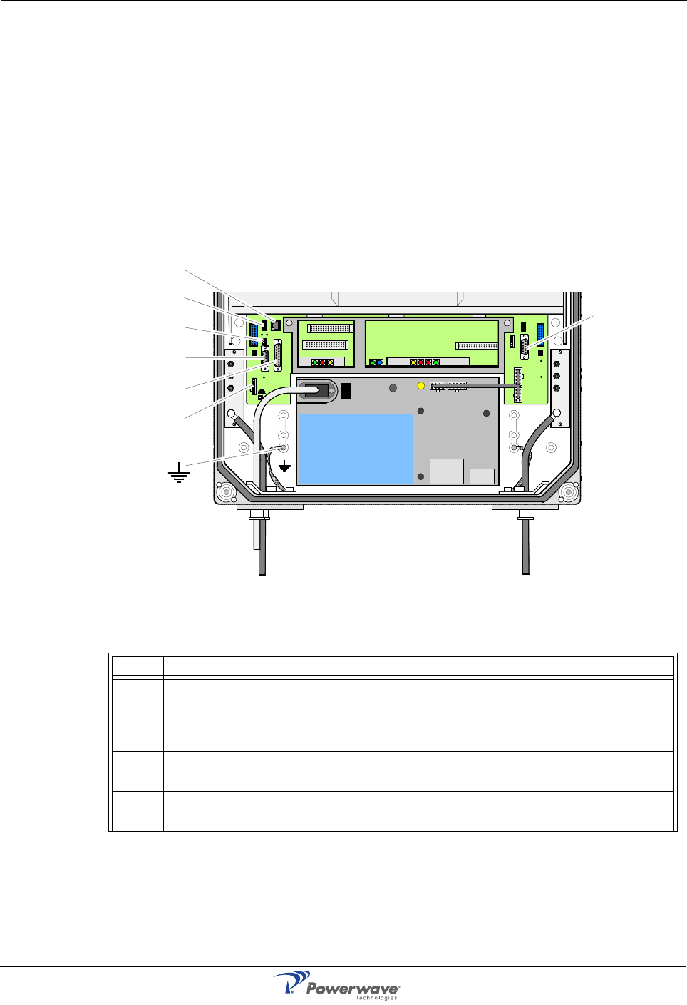
AR Standard Repeater PCBA Connections
2-12 044-05250 Rev A
PSU
The PSU is located in the bottom middle of the cabinet or in an equipped high cover as
illustrated in Figure 2-8. The PSU has all the voltages required for all repater types. It has
capacity for one repeater, including the radio circuitry, fiber optics, modem, etc. In some high
power repeater types, the PSU also supplies the BA. Multi-band high power repeaters always
require a second PSU. There are two PSU types with different input voltages:
1. 115/230V 50/60Hz, 300W input max.
2. 21- 60V DC, 300W input max.
The DIA provides most of the internal connection between the repeater units and to external
ports. Connectors involved in the installation are also located on the DIA. Table 2-13
describes these connections.
Figure 2-8 Power Supply Unit (PSU)
Table 2-13 PSU Connectors
Port Description
P27 Auxiliary Port (8-pin male) - Used to power the old RCU. It is located on the DIA
to the left in the cabinet. Pins 2 and 3 must always be interconnected to provide
the CU and ALI/RCI PCBs with voltage supply. If there is no cable connected,
pins 2 and 3 must be interconnected with a jumper.
P31 RS-232 PC Port (9-pin D-sub female) - Used for local PC communication. It is
located on the DIA to the right in the cabinet.
P32 RS-232 Modem port (9-pin D-sub male) - V.24 interface used for the old RCU.
It is located on the DIA to the left in the cabinet.
MS
DPX
ANT
TEST
DC
-30 dB
-20 dB MS
DPX
ANT
TEST
DC
-30 dB
-20 dB
POWER SUPPLY UNIT
AL LGON INNOVATI ON
SWEDEN M105 R6
1
PARKI NG
FOR W5
W5
8
P27 W6B 10
1
P33
ALARM
P23
LNA
UP-LINK
P32
MODEM
AUX1
P28
DOOR
5
9
61
116
1
1
M->S
P11
P34
8
9
15
P26
15 16
S->M
12
389
P36
5
X0A
X0B
2V2 116
P12 P13
1
1
1
16
16
16
P4
P5
P6
c
b
a
c
b
a
c
b
a
c
b
a
1P232
1
b
a
116P3
16 116
P14
1
V1
1
1
1
1
1
4
6
1
15
6
915
2
16
1
2
4
5
8
5
P35
P21
PSU
6
10
P31
PC
P29
P24
P25
GND
7
6V6
LNA
DOWN- LINK
LED
P22
1
2
P33
P27
P3
1
P32
P34
P28
P36

PCBA Connections AR Standard Repeater
044-05250 Rev A 2-13
P33 Alarm Port (15-pin D-sub female) - Used for external alarm sensors and alarm
equipment. It is located on the DIA to the left in the cabinet. The port has four
alarm inputs, EAL1 – EAL4, and two alarm outputs.
The four alarm inputs are low-level inputs with common ground (AIC). Use
insulated switch or relay to initiate alarms (open switches in normal operating
mode, closed switches cause alarm). The alarm switch connection can be tog-
gled between active open and active closed. This is further described in the
OM-Online User Manual and the Advanced Repeater OMS User Manual.
The alarm input voltage ratings, related to ground (AIC), are: Vinmax= 5.5V,
Vinmin= –0.5V
The four alarm inputs are connected to the following pins:
Pin 14 AI1 External alarm input 1 - EAL1
Pin 15 AI2 External alarm input 2 - EAL2
Pin 7 AI3 External alarm input 3 - EAL3
Pin 8 AI4 External alarm input 4 - EAL4
Pin 6 AIC Ground.
See also the P28 door switch port below.
Two alarm outputs are 1 pole closing and 1 pole opening relay outputs insu-
lated from each other. Maximum ratings, related to ground or any other alarm
terminal, are 50V AC / 60V DC. The alarm outputs are defined as follows:
Pin 9 and 1 AO1 and AO8 Closed when operating, otherwise open.
Pin 10 and 2 AO6 and AO7 Open when operating, otherwise closed.
Pin 11 and 3 AO2 and AO5 Closed at alarm state, otherwise open.
Pin 12 and 4 AO3 and AO4 Open at alarm state, otherwise closed.
P28 Door switch port - Normally, alarm input AI4 is used for repeater door opening
alarm EAL4 which is arranged using an optional door switch. Signal AI4 and
AIC are thus available also in the P28 connector, to which the door switch is
connected. It is located on the DIA to the left in the cabinet. The EAL4 door
switch alarm is activated 10 – 30 seconds after the cover has been opened.
P34 WLI Port (8-pin RJ45 female) - Used for the WLI network (R2R). It is located on
the DIA to the left in the cabinet.
P36 WLI Port (5-pin male) - Used for the WLI network (IP or R2R). It is located on
the DIA to the left in the cabinet. Connecting P111 or P112 on a FON to this
port, an FLI network is interconnected to a WLI network (IP or R2R) making all
the included repeaters in both the networks accessible.
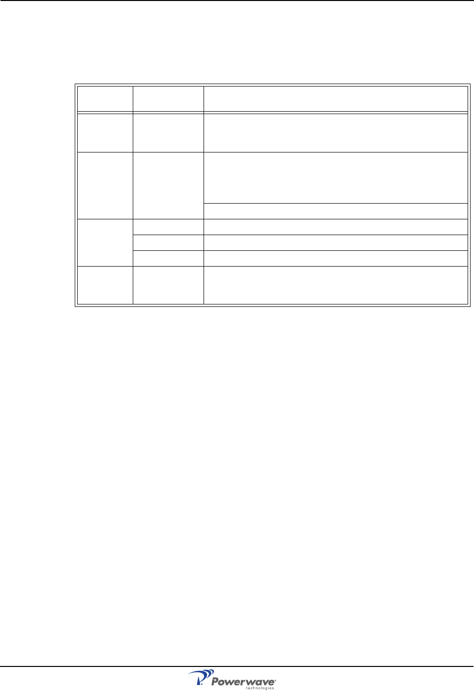
AR Standard Repeater PCBA Connections
2-14 044-05250 Rev A
Software and Hardware Compatibility
There are different versions of repeater CU software which can be combined with PCBAs of
various revisions. These have unique part numbers and revision information. Below, you will
find a table of repeater software currently available in combination with CU PCBA revisions.
Table 2-14 Hardware / Software Compatibility
This information is accurate as of 1/31/2007. As new versions of hardware and software are
released without prior noticing, contact your Powerwave sales representative if in doubt about
the latest revision status.
For detailed information, refer to the release notes for the CU software to be downloaded
(normally found in the readme.txt file provided with the program files).
CU PCBA
part # CU Software
part # Comments
K103/1
or
K103/2
SA102 01/2 For GSM channel selective = 4 channels, band selective
800-900MHz fixed bandwidth only, and combined repeater
(800/900MHz). No traffic statistics.
K103/2 SA102 02/1 For GSM, DCS, PCS channel selective = 8 channels, band
selective 800 – 900MHz fixed or adjustable bandwidth,
band selective 1800MHz or 1900MHz and combined
repeater. Supports R2R link.
Supports stacked channels.
K103/2 SA102 02/2 For 800/1900MHz CDMA = 4 channels.
SA102 02/4 For 800/1900MHz channel selective operation.
SA102 02/5 For 800/1900MHz band selective operation.
K103/3 SA102 06/x
SA102 07/x
SA102 08/x
More memory. MAC ID is added on the PCBA. R2R func-
tionality integrated.

044-05250 Rev A 3-1
Chapter 3
Installation
Introduction
This chapter contains unpacking, inspection and installation instructions for installing and
powering up the AR Standard Repeater.
Site Survey
Powerwave recommends that a site survey be performed prior to equipment ordering or
installation. Performing a detailed site survey reduces or eliminates installation and turn-up
delays. Pay particular attention to power plant capacity, cooling needs, floor space, and RF/
DC cabling/breaker requirements. Cabinet dimensions, clearance dimensions, and weights
are listed in Chapter 5.
Unpacking and Inspection
This equipment has been operated, tested, and calibrated at the factory. Carefully open
containers to remove equipment. Retain all packing material that can be reassembled in the
event unit must be returned to the factory. Perform the following steps:
• Visually inspect equipment for damage that may have occurred during shipment. If pos-
sible, in the presence of the delivery person.
• Check for evidence of water damage, bent or warped chassis, loose screws or nuts, or
extraneous packing material in connectors.
If equipment is damaged, file a claim with the carrier once the extent of any damage is
assessed.
If equipment must be returned to factory, please contact factory for a Return Material
Authorization (RMA). See Chapter 4.
Repeater Location
Powerwave repeaters are designed with a weather proof outdoor cabinet that can be
mounted without any kind of shelter from rain, snow or hail. The same unit can be installed
indoors. A preferable site for the repeater is a location free of obstructions, easily accessible
and allows for proper air-flow and ventilation.
If a repeater is installed outdoor and can be exposed to direct sunshine, it is essential that air
can circulate around the repeater with no obstacle. The operating temperature must not
exceed 131°F (55°C). A shelter can be used to shade the repeater from direct sunshine.
Never open a repeater when rain, snow, hail, high humidity or high winds are present unless
some kind of temporary shelter can be erected. Limitations for very bad weather are found in
the next section.
Mounting
The AR repeater is easy to mount using the provided mounting bracket, illustrated in Figure
3-1, which has 9/16” (14mm) holes for 3/8” (10mm) or 1/2” (12mm) fixing screws. Clamps
with C-C measures of 3.5” (90mm), 5.3” (135mm), 5.7” (144mm), 8.1” (205mm), 9.8”
(250mm), and 11.8” (300mm) can be used as well. The vertical C-C measure for these are
16.2” (411mm). There is a 9/16” (14mm) single hole in the middle of the mounting bracket,
marked ‘A’ in the figure, which is intended for a locking screw to lock the bracket into place.
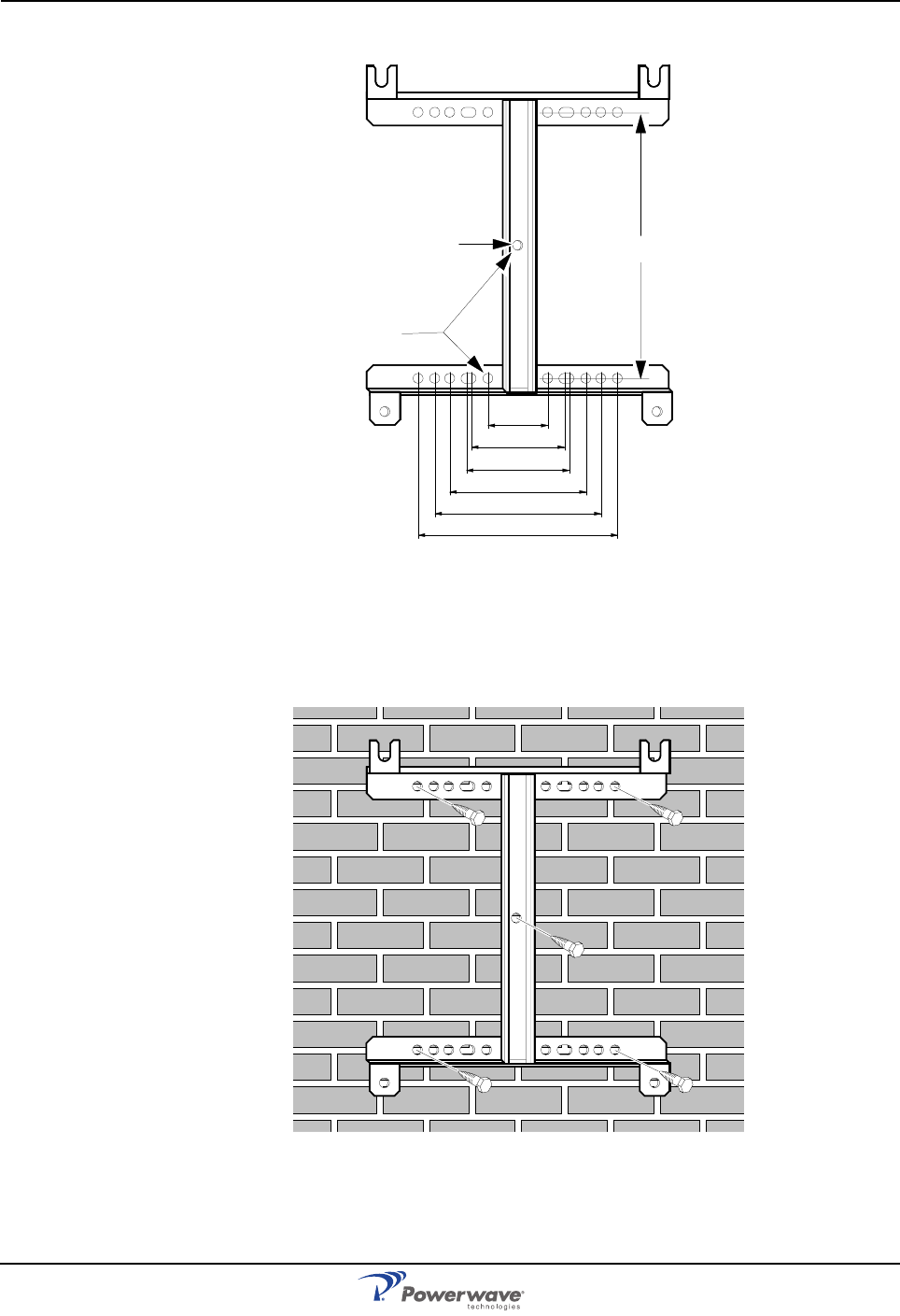
Mounting AR Standard Repeater
3-2 044-05250 Rev A
Figure 3-1 Mounting bracket
Normally, the AR repeater is mounted on a wall, pole or mast. Figure 3-2 illustrates the
installation of the mounting bracket on a wall using four fixing screws and a locking screw.
Figure 3-2 Mounting bracket installation on wall
90
135
144
205
250
300
Ø14
A411
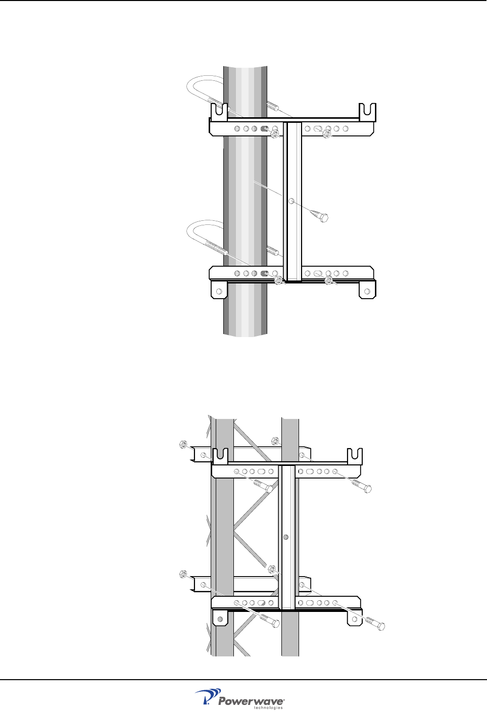
AR Standard Repeater Mounting
044-05250 Rev A 3-3
Figure 3-3 illustrates the installation of the mounting bracket on a pole using two 5.7”
(144mm) U-shaped clamps and a locking screw.
Figure 3-3 Attaching the bracket to a pole
Figure 3-4 illustrates a mast installation using two 11.8” (300mm) bar-shaped clamps and no
locking screw.
Figure 3-4 Attaching the bracket to a mast
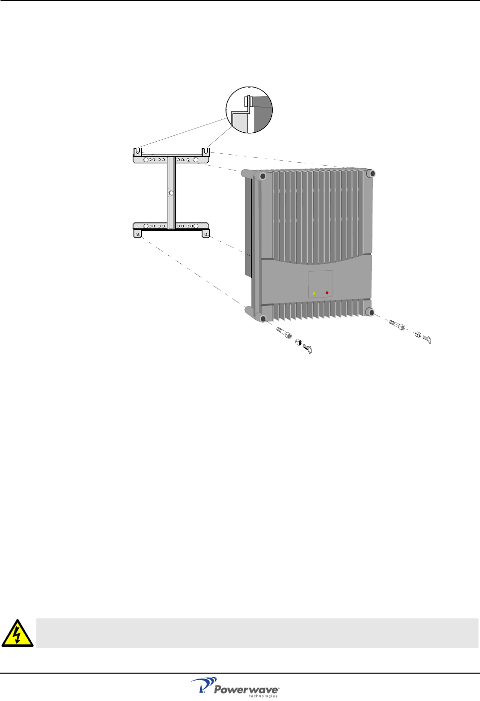
Connections AR Standard Repeater
3-4 044-05250 Rev A
After installing the mounting bracket, hang the repeater on the upper supports, as illustrated
in Figure 3-5. Tighten the upper and lower mounting screws to secure it into place. Locking
cylinders, used to prevent unauthorized removal of the repeater, can be inserted and locked
with a key after the lower screws have been tightened. Make sure the donor antenna,
directed towards the BTS antenna, and the service antenna, directed towards the area to be
covered by the repeater, are mounted and installed properly.
Figure 3-5 Attaching the repeater to the bracket
Connections
This section describes general examples of how to connect the input and output ports on the
following repeater types:
• RF to RF repeaters
• BMU (RF to fiber optics)
• RMU (RF to fiber optics)
• FOR (fiber optics to RF)
Main Power and Grounding
Local regulations need to be followed for the main power connection. AR repeaters are
approved in accordance with EN and UL/cUL regulations. This is, however, only valid if a
classified power cord is used. For the repeater to meet these regulations you must select one
of the following classified and approved cord types:
• EN – H 05 W5 - F HMR
• UL – AWM Style 2587
• CSA– AWM 1 A/B 11 A/B
For outdoor use, the power cord should meet at least IP65 encapsulation requirements. Do
not turn the main power on until you are ready to commission the repeater
WARNING: For repeaters supplied from the main power source, the main outlet must be grounded.
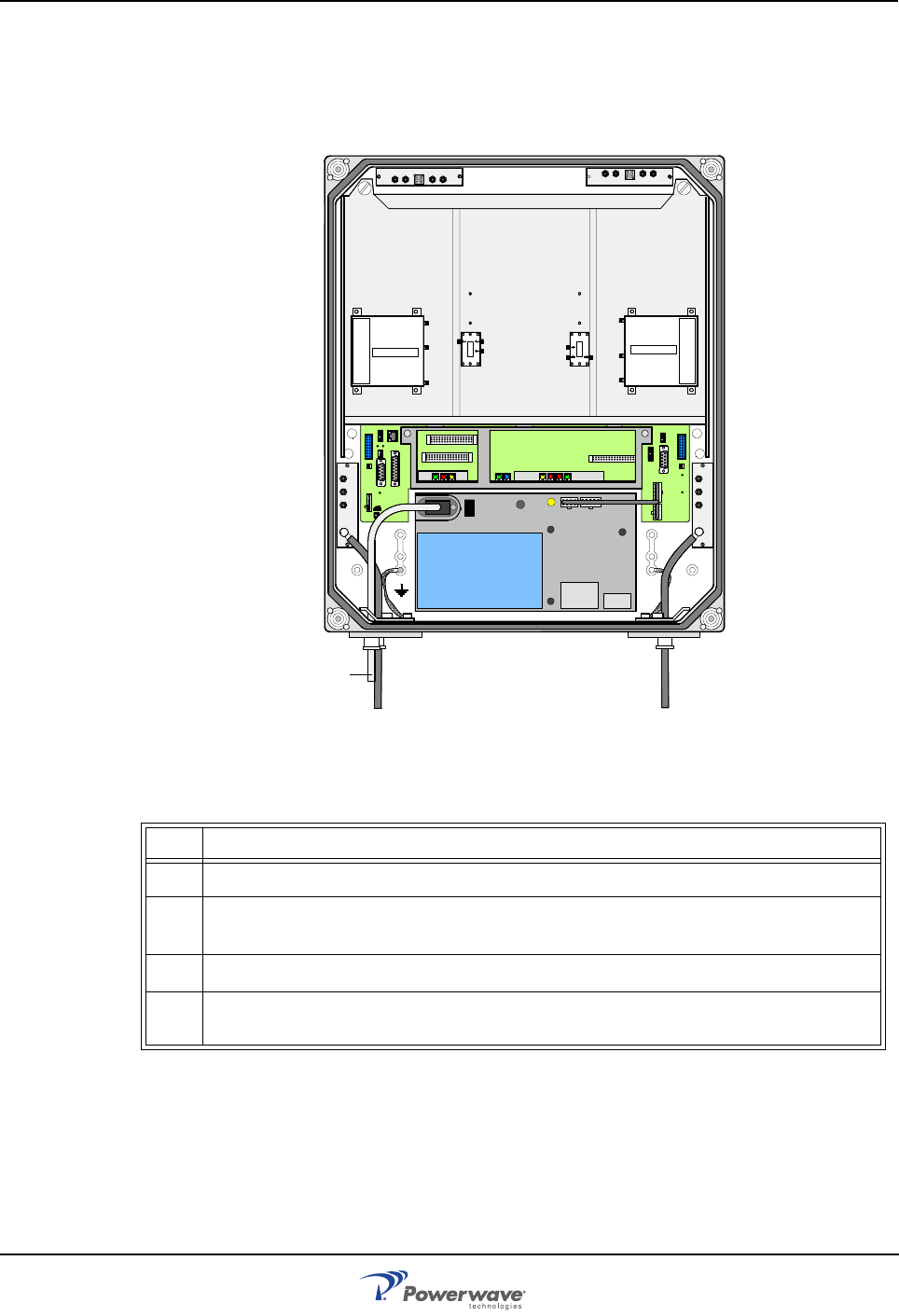
AR Standard Repeater Connections
044-05250 Rev A 3-5
RF-to-RF Repeater Connections
Figure 3-6 illustrates the cable connections applicable for standard and high power repeaters
and Table 3-1 describes the steps for making the connections. The donor antenna or RF
cable from the BTS is connected to the right and the service antenna is connected to the left
in the cabinet.
Figure 3-6 RF-to-RF Repeater Connections
Table 3-1 RF-to-RF Connections Procedure
Step Action
1 Mount AR Repeater
2Using N-type male connectors, connect the service and donor antenna coaxial
cables (or RF cable from the BTS if no donor antenna is used).
3Verify that the connector ports are tagged as such.
4Connect station ground, if to be used, and mount the main power plug to the
main power cord but do not connect the main power.
MS
DPX
ANT
TEST
DC
-30 dB
-20 dB MS
DPX
ANT
TEST
DC
-30 dB
-20 dB
POWER SUPPLY UNIT
ALLGON INNOVATION
SWEDEN M105 R6
1
PARKING
FOR W5
W5
8
P27 W6B 10
1
P33
ALAR M
P23
LNA
UP-LINK
P32
MODEM
AUX1
P28
DOOR
5
9
61
116
1
1
M->S
P11
P34
8
9
15
P26
15 16
S->M
12
389
P36
5
X0A
X0B
2V2 116
P12 P13
1
1
1
16
16
16P4
P5
P6
c
b
a
c
b
a
c
b
a
c
b
a
1P232
1
b
a
116P3
16 116
P14
1
V1
1
1
1
1
1
4
6
1
15
6
915
2
16
1
2
4
5
8
5
P35
P21
PSU
6
10
P31
PC
P29
P24
P25
GND
7
6V6
LNA
DOWN-LINK
LED
P22
1
2
OUT
LOW
IN+7V AT TOUT2 OUT1
LNA
DL
OUT
LOW IN ATT +7V OUT1 OUT2
LNA
UL
PSU
Service Donor
Mains
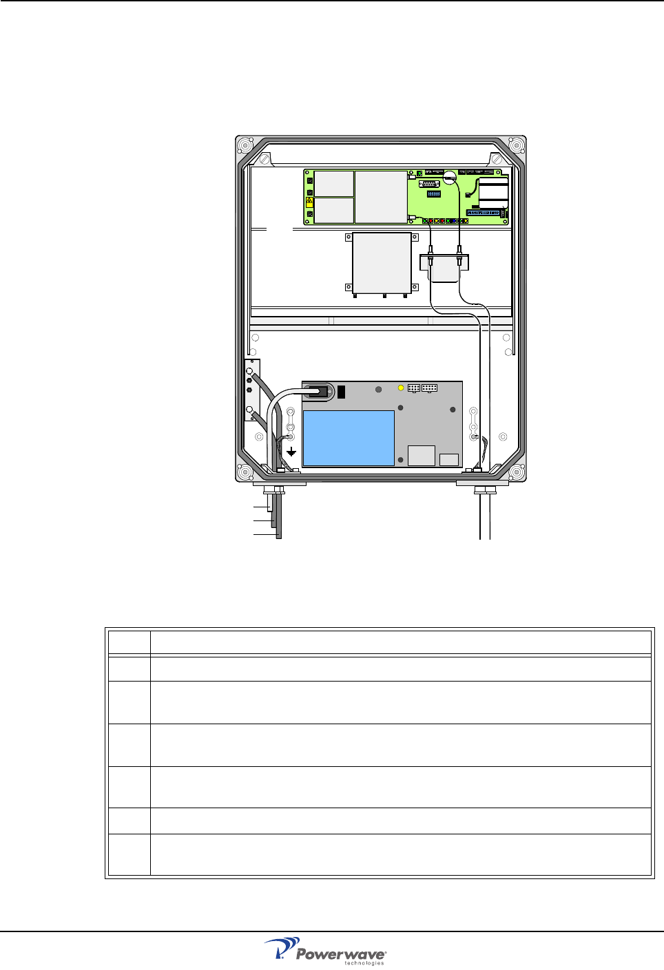
Connections AR Standard Repeater
3-6 044-05250 Rev A
BMU RF to Fiber Optic Connections
Figure 3-7 illustrates a BMU with separate TX/RX fiber optic cables to one FOR. By using
WDMs and OSPs, up to four FORs, or eight using a high cover, can be fed in parallel by one
BMU with double or single fiber optic cables. Table 3-2 describes the steps for making the
connections.
Figure 3-7 BMU RF-to-Fiber Optic Connections
Table 3-2 BMU RF-to-Fiber Connections Procedure
Step Action
1 Mount AR Repeater
2Using N-type male connectors, connect the BTS antenna output RF cable to the
ANT port of the DC unit located on the left in the cabinet.
3Connect an RF cable from the DPX port of the DC unit located on the left to the
BTS antenna using an N-type male connector
4Connect the TX and RX fiber optic cables from the FON located in the upper part
of the FOU to a FOR.
5Connect station ground, if to be used
6Mount the main power plug to the main power cord but do not connect the main
power.
MS
DPX
ANT
TEST
DC
-30 dB
-20 dB
POWER SUPPLY UNIT
FOU
TX RX
PSU
P102
P130
Beryllium
oxide
hazar d
P103
P101
P114
P108P116P111
P105P109P115
P106
P104
RX
TX
P113
P112
P110
FON
BTS FOR
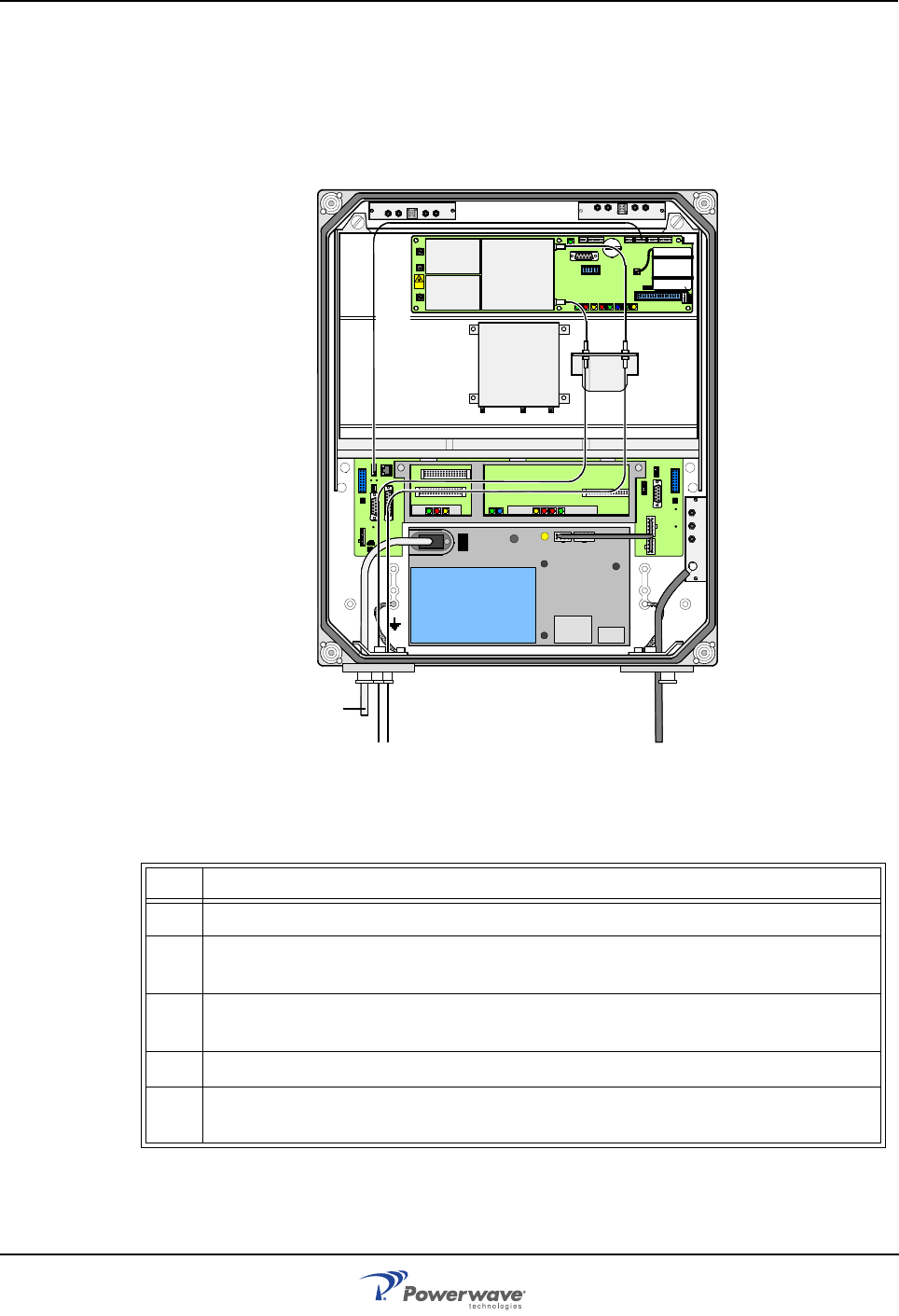
AR Standard Repeater Connections
044-05250 Rev A 3-7
RMU RF to Fiber Optic Connections
Figure 3-8 illustrates an RMU for donor antenna and separate TX/RX fiber optic cables to one
FOR. By using WDMs and OSPs, up to four FORs, or eight using a high cover, can be fed in
parallel by an RMU with double or single fiber communication. Table 3-3 describes the steps
for making the connections.
Figure 3-8 RMU RF-to-Fiber Optic Connections
Table 3-3 RMU RF-to-Fiber Connections Procedure
Step Action
1 Mount AR Repeater
2Connect the donor antenna coaxial cable to the right in the cabinet using an N-
type male connector
3Connect the TX and RX fiber optic cables from the FON located in the upper part
of the FOU to an FOR
4Connect station ground, if to be used
5Mount the main power plug to the main power cord but do not connect the main
power.
MS
DPX
ANT
TEST
DC
-30 dB
-20 dB
POWER SUPPLY UNIT
ALLGON INN OVATION
SWEDEN M105 R6
1
PARKING
FOR W5
W5
8
P27 W6B 10
1
P33
ALAR M
P23
LNA
UP-LINK
P32
MODEM
AUX1
P28
DOOR
5
9
61
116
1
1
M->S
P11
P34
8
9
15
P26
15 16
S->M
12
389
P36
5
X0A
X0B
2V2 116
P12 P13
1
1
1
16
16
16
P4
P5
P6
c
b
a
c
b
a
c
b
a
c
b
a
1P232
1
b
a
116P3
16 116
P14
1
V1
1
1
1
1
1
4
6
1
15
6
915
2
16
1
2
4
5
8
5
P35
P21
PSU
6
10
P31
PC
P29
P24
P25
GND
7
6V6
LNA
DOWN-LINK
LED
P22
1
2
TX
FOR
OUT
LOW IN ATT +7V OUT1 OUT2
LNA
UL OUT
LOWIN+7V ATTOUT2 OUT1
LNA
DL
FOU
PSU
R2R
P102
P130
Beryllium
oxide
hazar d
P103
P101
P114
P108P116P111
P105P109P115
P106
P104
RX
TX
P113
P112
P110
FON
RX
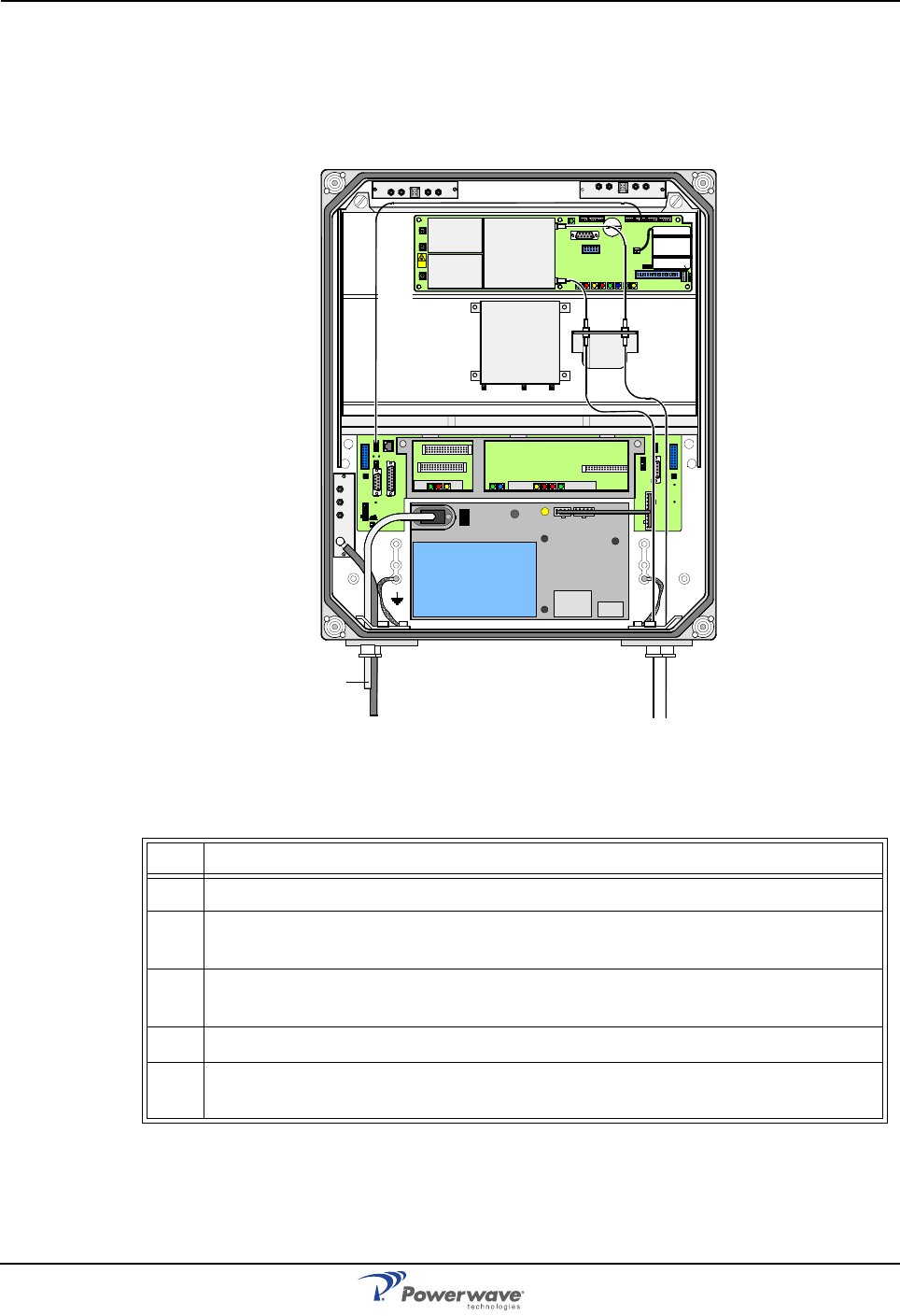
Connections AR Standard Repeater
3-8 044-05250 Rev A
FOR RF to Fiber Optic Connections
Figure 3-9 illustrates a FOR for service antenna and separate TX/RX fiber optic cables from a
BMU. By adding WDMs and OSPs, a number of FORs can be fed by one BMU with double or
single fiber communication. Table 3-4 describes the steps for making the connections.
Figure 3-9 FOR RF-to-Fiber Optic Connections
Table 3-4 FOR RF-to-Fiber Connections Procedure
Step Action
1 Mount AR Repeater
2Connect the service antenna coaxial cable to the left in the cabinet using an N-
type male connector.
3Connect the TX and RX fiber optic cables from the BMU to the FON located in
the upper part of the FOU
4Connect station ground, if to be used
5Mount the main power plug to the main power cord but do not connect the main
power.
MS
DPX
ANT
TEST
DC
-30 dB
-20 dB
POWER SUPPLY UNIT
ALLGON INNOVATION
SWEDEN M105 R6
1
PARKING
FOR W5
W5
8
P27 W6B 10
1
P33
ALAR M
P23
LNA
UP-LINK
P32
MODEM
AUX1
P28
DOOR
5
9
61
116
1
1
M->S
P11
P34
8
9
15
P26
15 16
S->M
12
389
P36
5
X0A
X0B
2V2 116
P12 P13
1
1
1
16
16
16
P4
P5
P6
c
b
a
c
b
a
c
b
a
c
b
a
1P232
1
b
a
116P3
16 116
P14
1
V1
1
1
1
1
1
4
6
1
15
6
915
2
16
1
2
4
5
8
5
P35
P21
PSU
6
10
P31
PC
P29
P24
P25
GND
7
6V6
LNA
DOWN-LINK
LED
P22
1
2
TX
OUT
LOWIN+ 7V ATTOUT2 OUT1
LNA
DL
OUT
LOW IN ATT +7V OUT1 OUT2
LNA
UL
RX
FOU
PSU
R2R
P102
P130
Beryllium
oxide
hazar d
P103
P101
P114
P108P116P111
P105P109P115
P106
P104
RX
TX
P113
P112
P110
FON
BMU
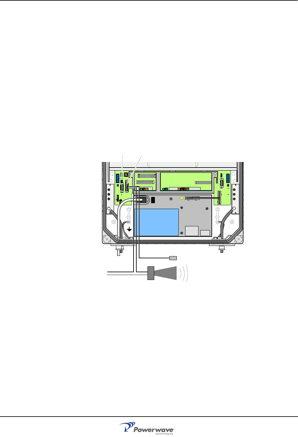
AR Standard Repeater Optional Connections
044-05250 Rev A 3-9
Optional Connections
Alarms
Alarm signals from external sensors are received by an ALI or RCI which forwards them to
the CU. The RCI is used if the repeater has an RCU. The software on the CU can activate
acoustic or visual alarms or direct the alarm to the P33 alarm port for forwarding via an RCU
to an OM-Online or OMS workstation. Alarms can also be handled by the FON. Alarms can
be configured through OM-Online or OMS.
External Alarm
Burglary, fire or other external alarms can be handled by the AR repeaters. External alarm
sensors and alarm signals are connected to the P33 alarm port located to the left in the
cabinet as illustrated in Figure 3-10.
The P33 alarm port is described in Chapter 2. The cable for this installation is taken through a
strain relief bushing at the bottom of the repeater. For repeaters without CU and DIA PCBAs,
a BMU for instance, the external alarm is connected to the P109 port on the FON. P109 is
described in the FON PCBA section in Chapter 2.
Figure 3-10 External alarm connection
Door Open Alarm
A door open alarm can be handled by all repeater types that have a CU PCBA. This is
arranged with a door switch connected to port P28 illustrated in Figure 3-10. P28 and the
connection is described in Chapter 2.
Fiber Link Interface (FLI)
The FLI feature makes it possible to interconnect repeaters that have a FON (BMU, RMU and
FOR). By using an RF distribution fiber network, no wire or other communication device is
required. Communication with repeaters in a mixed FLI and WLI network is possible.
MS
DPX
ANT
TEST
DC
-30 dB
-20 dB
MS
DPX
ANT
TEST
DC
-30 dB
-20 dB
POWER SUPPLY UNIT
ALLGON INNOVATION
SWEDEN M105 R6
1
PARKING
FOR W5
W5
8
P27 W6B 10
1
P33
ALARM
P23
LNA
UP-LINK
P32
MODEM
AUX1
P28
DOOR
5
9
61
116
1
1
M->S
P11
P34
8
9
15
P26
15 16
S->M
12
389
P36
5
X0A
X0B
2V2 116
P12 P13
1
1
1
16
16
16
P4
P5
P6
c
b
a
c
b
a
c
b
a
c
b
a
1P232
1
b
a
116P3
16 116
P14
1
V1
1
1
1
1
1
4
6
1
15
6
915
2
16
1
2
4
5
8
5
P35
P21
PSU
6
10
P31
PC
P29
P24
P25
GND
7
6V6
LNA
DOWN-LINK
LED
P22
1
2
P28 P33
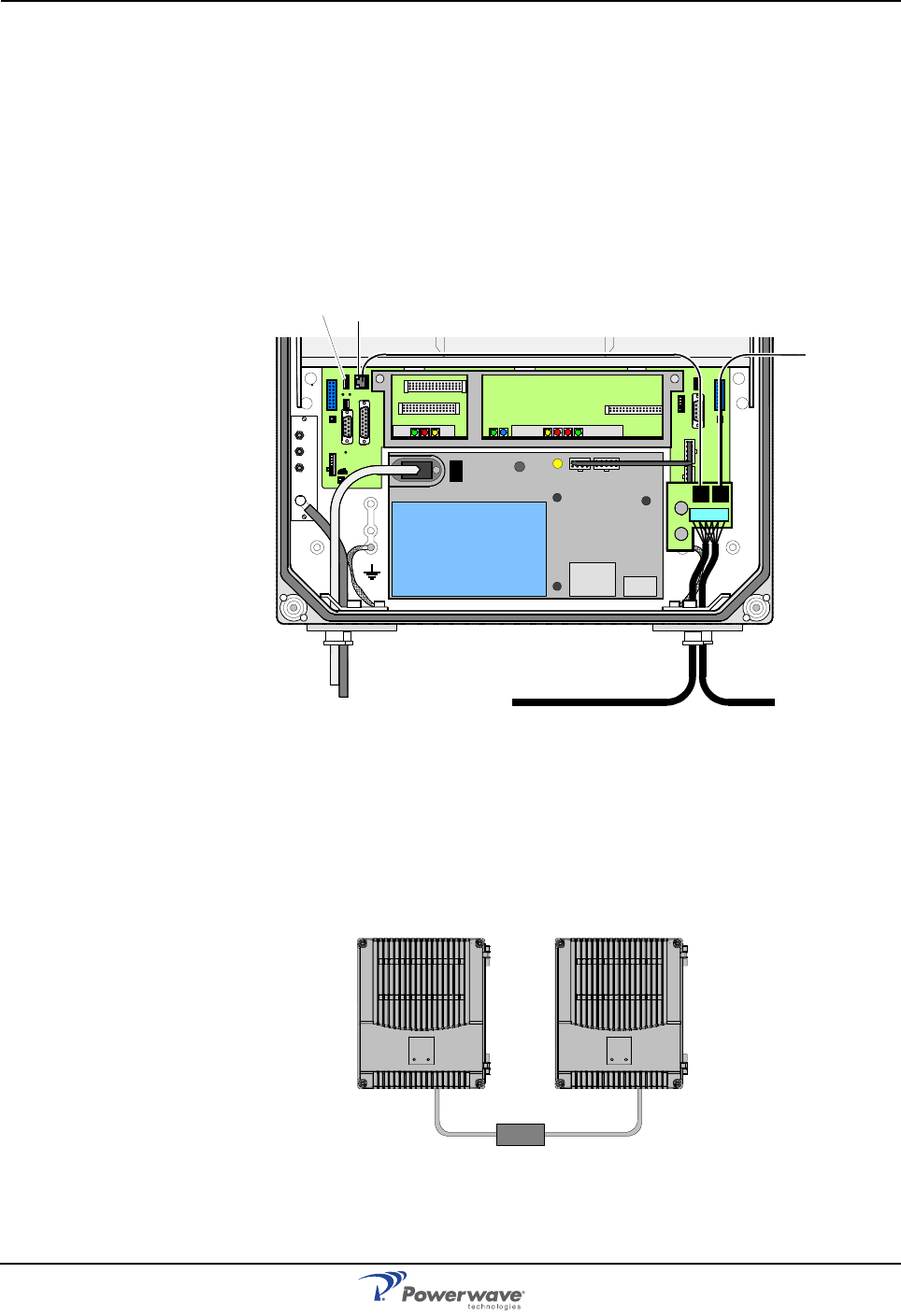
Optional Connections AR Standard Repeater
3-10 044-05250 Rev A
Wire Link Interface (WLI) Network (IP to R2R)
Two types of WLI networks are available for the Powerwave repeaters: Internet Protocol (IP)
and Repeater-to-Repeater Link (R2R). For R2R networks: If the repeater has a previous CU
PCBA model (K103/2), then a RIA PCBA is required. Further information about the IP and
R2R network is located in the OM-Online User Manual.
The network cables are connected to P34 or P36 WLI ports on the DIA PCBA as illustrated in
Figure 3-11. The cables can either be interconnected at the P1 terminal on the connector
PCBA located to the right in the cabinet or to both P34 and P36. For repeaters without CU
and DIA PCBAs, the BMU for instance, the network cables are connected to port P111 and
P112 on the FON.
Figure 3-11 IP and R2R Network Connection
Any cable type can be used for indoor installations. For outdoor installations, the Li 2YC11Y,
2x2xAWG24/222, non-halogen, Metrofunkkabel-Union cable type is recommended. Use
strain relief bushings or connectors at the bottom of the repeater. If the link cable between
two repeaters is longer than 25 meters, an RS-485 repeater is required as illustrated in Figure
3-12 below.
Figure 3-12 RS-485 Cable Repeater
MS
DPX
ANT
TEST
DC
-30 dB
-20 dB
POWER SUPPLY UNIT
ALLGON INNOVATION
SWEDEN M105 R6
1
PARKI NG
FOR W5
W5
8
P27 W6B 10
1
P33
ALARM
P23
LNA
UP-LINK
P32
MODEM
AUX1
P28
DOOR
5
9
61
116
1
1
M->S
P11
P34
8
9
15
P26
15 16
S->M
12
389
P36
5
X0A
X0B
2V2 116
P12 P13
1
1
1
16
16
16
P4
P5
P6
c
b
a
c
b
a
c
b
a
c
b
a
1P232
1
b
a
116P3
16 116
P14
1
V1
1
1
1
1
1
4
6
1
15
6
915
2
16
1
2
4
5
8
5
P35
P21
PSU
6
10
P31
PC
P29
P24
P25
GND
7
6V6
LNA
DOWN- LINK
LED
P22
1
2
P3 P2
P1
P36 P34
>25m
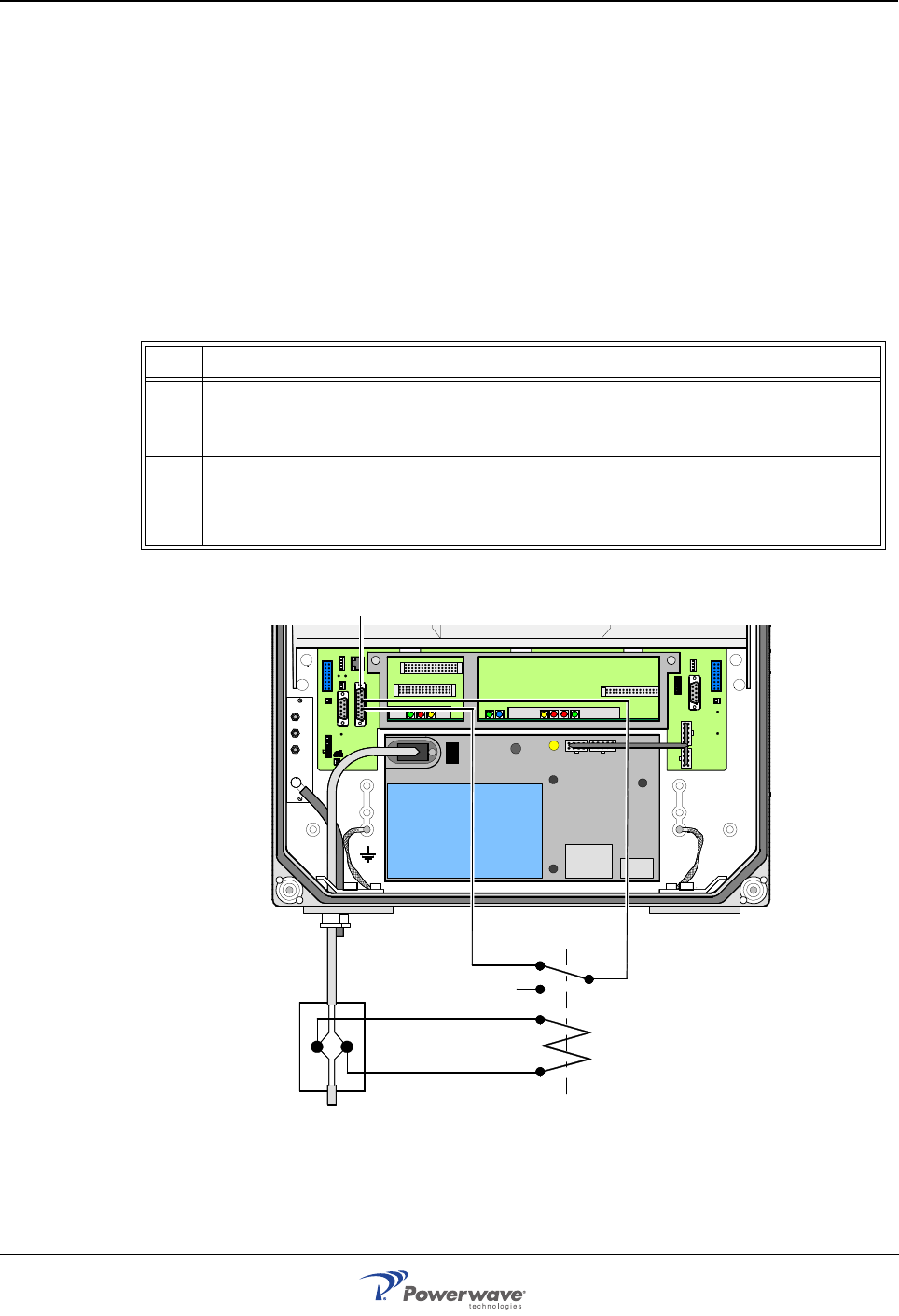
AR Standard Repeater Optional Connections
044-05250 Rev A 3-11
Main Power Breakdown Relay
To be able to distinguish PSU faults from power failure, a main power breakdown relay can be
used. This relay is not included in the AR repeater and has to be mounted outside the
repeater cabinet. The relay intended for this purpose must fulfil the following specifications:
Closing time: Max. 30 milliseconds
Insulation coil/contact: Min. 4KV
A main power connected relay must also be in compliance with valid local regulations. Figure
3-13 illustrates the connection points and Table 3-5 lists the steps for making the connections.
Table 3-5 Main Power Breakdown Relay Connection
Figure 3-13 Main Power Breakdown Relay Connection
Step Action
1 Connect a currentless closed relay contact to pin AI1 and AIC on the P33 alarm connec-
tor. An alarm is initiated by short-circuiting the pins. For the BMU the main power break-
down cables are connected to pin AI1 and AIC in the P109 port on the FON.
2 Connect the relay coil. It must be supplied from the same fuse as the repeater.
3 After commissioning, select Mains Breakdown in the alarm configuration window in OM-
Online or OMS. Refer to the OM-Online User Manual.
MS
DPX
ANT
TEST
DC
-30 dB
-20 dB
POWER SUPPLY UNIT
ALLGON INNOVATION
SWEDEN M105 R6
1
PARKI NG
FOR W5
W5
8
P27 W6B 10
1
P33
ALARM
P23
LNA
UP-LINK
P32
MODEM
AUX1
P28
DOOR
5
9
61
116
1
1
M->S
P11
P34
8
9
15
P26
15 16
S->M
12
389
P36
5
X0A
X0B
2V2 116
P12 P13
1
1
1
16
16
16
P4
P5
P6
c
b
a
c
b
a
c
b
a
c
b
a
1P232
1
b
a
116P3
16 116
P14
1
V1
1
1
1
1
1
4
6
1
15
6
915
2
16
1
2
4
5
8
5
P35
P21
PSU
6
10
P31
PC
P29
P24
P25
GND
7
6V6
LNA
DOWN- LINK
LED
P22
1
2
P33:AICP33:AI1
P33
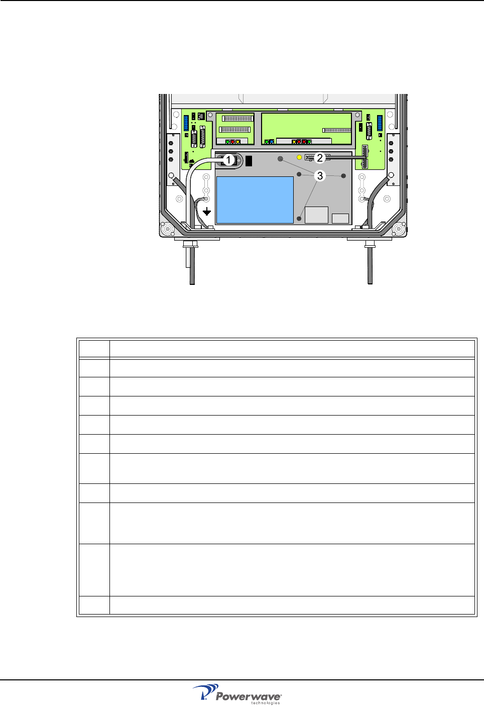
Optional Connections AR Standard Repeater
3-12 044-05250 Rev A
21-60 Volt DC PSU Installation
The 115/220 VAC PSU can be replaced with a 21 to 60 VDC DC PSU Figure 3-14 illustrates
the location of the mounting screws and power connectors of the PSU and Table 3-6 lists the
replacement procedure.
Figure 3-14 PSU Connections
Table 3-6 PSU Replacement Procedure
Step Action
1 Disconnect main power.
2 Remove the main power plug from the PSU ('1' in Figure 3-11).
3 Disconnect the power cable bundle connectors (2) on the PSU.
4 Loosen the four fixing screws (3) using a 5mm Allen key and remove the PSU.
6 Examine the removed PSU and identify the supply voltage for the WRH (13.5V or 27V).
7 Set the new PSU to the correct supply voltage by moving the jumper as illustrated on the
PSU. This must be done before the PSU is mounted in the repeater.
8 Mount the PSU with the four fixing screws (3).
9 Connect the PSU to the DIA PCBA (2) with a cable marked VE007 98/1. This cable must
be used even if one connector will be left over at the DIA PCBA (previous versions of the
DIA had only one connector).
10 Connect the DC power cable. The supplied cable should have a radiation limiter. The +
pole should be connected to one of the left terminals in the PSU connector with the brown
part of the DC cable. The – pole should be connected to one of the right terminals in the
PSU connector with the blue part of the DC cable.
11 Apply power and verify the yellow LED on the PSU lights.
MS
DPX
ANT
TEST
DC
-30 dB
-20 dB
MS
DPX
ANT
TEST
DC
-30 dB
-20 dB
POWER SUPPLY UNIT
ALLGON INNOVATION
SWEDEN M105 R6
1
PARKING
FOR W5
W5
8
P27 W6B 1 0
1
P33
ALARM
P23
LNA
UP-LINK
P32
MODEM
AUX1
P28
DOOR
5
9
61
116
1
1
M->S
P11
P34
8
9
15
P26
15 16
S->M
12
3
89
P36
5
X0A
X0B
2V2 116
P12 P13
1
1
1
16
16
16P4
P5
P6
c
b
a
c
b
a
c
b
a
c
b
a
1P232
1
b
a
116P3
16 116
P14
1
V1
1
1
1
1
1
4
6
1
15
6
915
2
16
1
2
4
5
8
5
P35
P21
PSU
6
10
P31
PC
P29
P24
P25
GND
7
6V6
LNA
DOWN-LINK
LED
P22
1
2
PSU
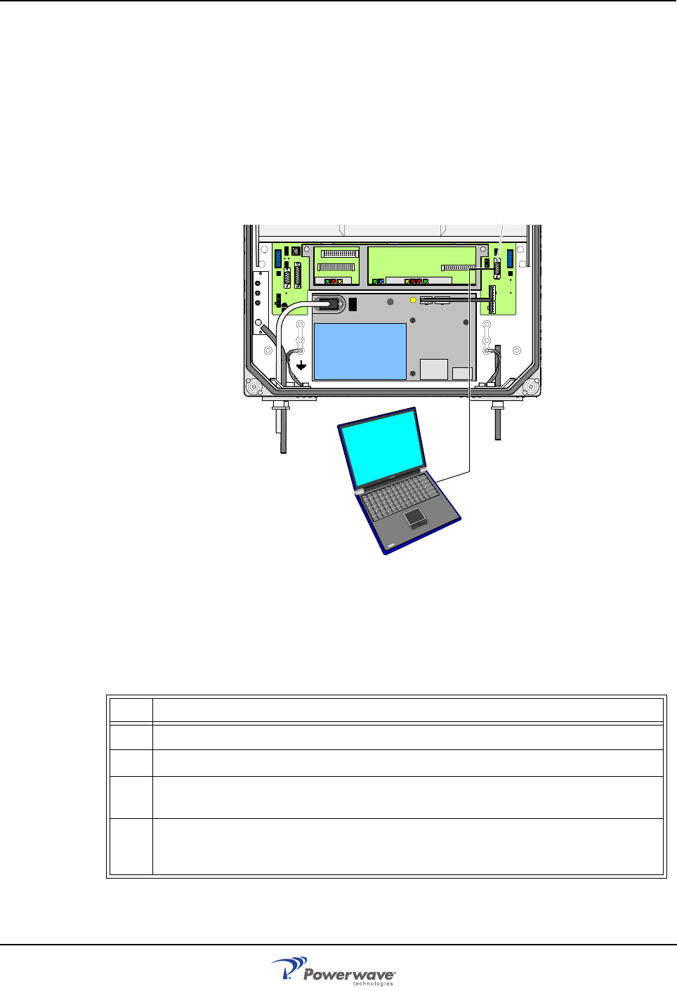
AR Standard Repeater Commissioning
044-05250 Rev A 3-13
Commissioning
Before proceeding, carefully read the Safety section and check all connections made during
the installation. To fulfill the IP65 weather protective requirements, ensure cable strain relief
bushings are properly tightened. Also, ensure gaskets at cable inlets and on the cabinet are
properly fitted and not damaged.
A repeater can be configured locally with OM-Online by connecting a standard serial cable
from the COM port on the PC to the P31 PC port (RS-232) located to the right in the cabinet
as illustrated in Figure 3-15. The P31 PC port is described in Chapter 2. OM-Online is
described in the OM-Online User Manual.
Figure 3-15 Connecting a PC for Local Access
For a BMU the PC is connected to the P106 port on the FON. The P106 port is described in
the FON section in Chapter 2.
Initial Startup
Table 3-7 Initial Statup Procedure
Step Action
1 Turn the main power on
2 Check the Yellow LED on the power supply unit. It must be a steady on
3 Check the four CU PCBA LEDs. Refer to the CU PCBA section in Chapter 2 for the cor-
rect power up indications
4 Check the three ALI PCBA LEDs or the corresponding LEDs on the RCI PCBA. Refer to
the ALI or RCI PCBA section in Chapter 2 for the correct power up indications. The LEDs
follow the alarm relays.
MS
DPX
ANT
TEST
DC
-30 dB
-20 dB
POWER SUPPLY UNIT
ALLGON INN OVATION
SWEDEN M105 R6
1
PARKING
FOR W5
W5
8
P27 W6B 10
1
P33
ALAR M
P23
LNA
UP-LINK
P32
MODEM
AUX1
P28
DOOR
5
9
61
116
1
1
M->S
P11
P34
8
9
15
P26
15 16
S->M
12
389
P36
5
X0A
X0B
2V2 116
P12 P13
1
1
1
16
16
16P4
P5
P6
c
b
a
c
b
a
c
b
a
c
b
a
1P232
1
b
a
116P3
16 116
P14
1
V1
1
1
1
1
1
4
6
1
15
6
915
2
16
1
2
4
5
8
5
P35
P21
PSU
6
10
P31
PC
P29
P24
P25
GND
7
6V6
LNA
DOWN-LINK
LED
P22
1
2
P31
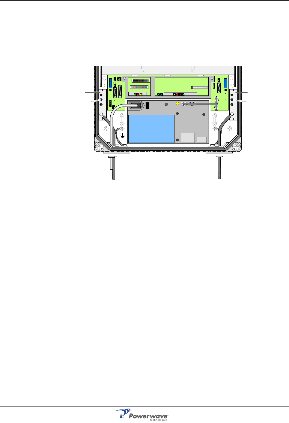
Commissioning AR Standard Repeater
3-14 044-05250 Rev A
Measuring Output Signal Levels
Uplink and downlink output signal test ports are located on the DCs at the donor and service
antenna connectors, provided the unit is configured with optional DCs. These test ports are
labeled TEST -30dB as illustrated in Figure 3-16 and are intended for signal measuring using
a spectrum analyzer.
Figure 3-16 Output Signal Level Ports
The coupling is approximately -30dB. There is no directivity in these test ports; both uplink
and downlink signal can be measured.
Voltage Testpoints
Testpoints are available on the DIA in the cabinet from which the various internal supply
voltages can be measured using a standard multimeter. The testpoint positions and names
are identified in the DIA section of Chapter 2.
MS
DPX
ANT
TEST
DC
-30 dB
-20 dB MS
DPX
ANT
TEST
DC
-30 dB
-20 dB
POWER SUPPLY UNIT
ALLGO N INNOVATIO N
SWEDEN M105 R6
1
PARKING
FOR W5
W5
8
P27 W6B 10
1
P33
ALARM
P23
LNA
UP-LINK
P32
MODEM
AUX1
P28
DOOR
5
9
61
116
1
1
M->S
P11
P34
8
9
15
P26
15 16
S->M
12
389
P36
5
X0A
X0B
2V2 116
P12 P13
1
1
1
16
16
16
P4
P5
P6
c
b
a
c
b
a
c
b
a
c
b
a
1P232
1
b
a
116P3
16 116
P14
1
V1
1
1
1
1
1
4
6
1
15
6
915
2
16
1
2
4
5
8
5
P35
P21
PSU
6
10
P31
PC
P29
P24
P25
GND
7
6V6
LNA
DOWN-LINK
LED
P22
1
2
DC
TEST
–30 dB
DC
TEST
–30 dB
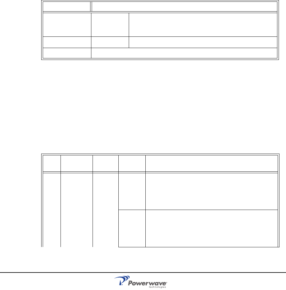
044-05250 Rev A 4-1
Chapter 4
Maintenance
Introduction
This chapter contains periodic maintenance and performance test procedures for the AR
Standard Repeater.
Periodic Maintenance
Periodic maintenance requirements are listed in Table 4-1, as well as the intervals at which
the tasks should be performed.
Table 4-1 Recommended Periodic Maintenance
Troubleshooting
The sections that follow contain a list of problems that could occur and a few suggested
actions that can correct the problem. If the suggested corrective action does not eliminate the
problem, please contact your Powerwave field representative or help line for further
instruction.
Clearing Alarm Faults
Table 4-2 contains a list of those alarms which can be generated in the repeater. Critical,
Error and Warning alarms can be sent automatically from a repeater to OM-Online and/or
OMS, stored and then viewed. These can be viewed in the Alarm window.
Table 4-2 Alarm Troubleshooting
Task Interval Action
Inspection of
cables and con-
nectors
12 months Inspect power, RF and Fiber cables for signs of damage or
wear (frayed insulation, cracks, punctures, etc.) Check con-
nections to be sure they are tight.
Optional Perform cable sweeps.
Clean equipment Clean as required depending on operating environment.
ID Alarm
Text Alarm
Unit Alarm Description
1 Power PSU Critical PSU1 in the cabinet does not work properly. A sum
signal from the PSU1 indicates that at least one volt-
age output has dropped. If no mains breakdown relay
is used, then the alarm will also be sent at mains
breakdown.
Ceasing PSU1 in the cabinet works properly again. Ceasing is
sent if the PSU1 works at start-up, and there is a cor-
responding critical PSU1 alarm logged in the Events
log. The repeater will restart when the power is back
and this alarm will be sent.

Troubleshooting AR Standard Repeater
4-2 044-05250 Rev A
PSU Critical PSU2 in the cover does not work properly. A sum sig-
nal from the PSU2 indicates that at least one voltage
output has dropped. If no mains breakdown relay is
used, then the alarm will also be sent at mains break-
down.
Ceasing PSU2 in the cover works properly again. Ceasing is
sent if the PSU2 works at start-up, and there is a cor-
responding critical PSU2 alarm logged in the Events
Log. The repeater will restart when the power is back
and this alarm will be sent.
FON Error The FON 10 Volt charger voltage is below limit. Sug-
gested remedy: Replace the FON
Ceasing The cause of the alarm has ceased.
2 Repeater
restart CU None Power on start, or user ordered reboot. Logged to
indicate a normal power up, or a restart ordered by
the operator.
Warning Software error restart, 1st – 7th time. Restart 1st to
7th time during a 14 day period. The counter is reset
every 14th day, counted from power up.
Error Software error restart 8th – 10th time. Restart 8th to
10th time during the 14 day period. At the 11th time,
the SW bank will be blocked and not used anymore
until a user ordered reset is performed, or power is
switched off/on.
3Mains
break-
down
Exter-
nal Critical The mains power is gone. Used with an external relay
indicating mains breakdown. The external relay
should be connected to External Alarm 1 and the
repeater configured to indicate this alarm. If no relay
is used, a mains breakdown will be reported as a
PSU fault.
Ceasing The mains power is back. Sent if there is a corre-
sponding critical mains breakdown alarm logged in
the Events Log. The repeater will restart when the
power is back.
4Alarm
reset CU None Alarm reset by the user. All alarms are reset. The
cause of the alarm will be re-evaluated and reported,
if still active.
5 Local bus
error CHA #,
BSA# Error Error when communicating on the bus. The CU has
no contact with the CHA or BSA PCBA, which is
taken out of service.
6 Main bkd
w backup Exter-
nal Error Used to indicate that the mains is no longer available.
Repeater is powered by external battery backup unit.
Suggested remedy: Check the mains power.
Ceasing The cause of the alarm has ceased.
7 Err in AD-
converter Warning The analog-to-digital converter on the CU PCBA does
not give reliable values.
8 New unit
detected None Compared to the last power on, the CU has recog-
nized at least one additional hardware unit.

AR Standard Repeater Troubleshooting
044-05250 Rev A 4-3
9 Inst. unit
lost Error Compared to the last power on, the CU lacks at least
one hardware unit.
10 EEPROM
error CU Error EEP read or write fail. Data cannot be written or read
from the EEPROM on the CU PCBA. User parame-
ters are stored in the EEPROM.
11 Log mem-
ory fault Error Log memory fault. Indicates that the log memory on
the CU PCBA is faulty. The repeater will not work. Not
available in all CU software versions.
12 High tem-
perature CU Warning The CU PCBA temperature is higher than 90°C.
Ceasing The CU PCBA temperature has fallen below 90°C.
13 REFO
error Error AR: Significant REFO drift or error detected by CU.
ALR: Low level from REFO detected by CU.
14 Ext refo
error Warning Suggested remedy: Check the reference source and
the cables.
15 CU bat-
tery fault CU Warning CU RAM battery fault. The battery for the RAM on the
CU PCBA has a voltage outside the normal 2.7 to 3.5
Volt. An alarm may be initiated at start-up if the
repeater has been stored out of power for a long time.
Suggested remedy: Ensure jumper P3 on the CU
PCBA is mounted to charge the battery.
Ceasing The cause of the alarm has ceased.
16 SW load
error CU Error Software load error. An error has occurred during a
software load process. The flash memory does not
contain a proper software. Suggested remedy: Check
the CU software using the OM-Online SW Manager.
Do NOT restart the repeater.
17 Log
cleared CU None Log memory has been cleared. The check sum in the
Events Log memory is faulty. The log is cleared. Can
be caused of a bad RAM battery backup or low volt-
age to the RAM.
18 RTC
restarted CU None The time is changed by the operator (logged to keep
track of changes made to the RTC).
Warning Time reset to 1994-01-01. The RTC was unable to
keep track of the time and did a reset. Suggested
remedy: Ensure jumper P3 on the CU PCBA is
mounted to charge the battery.
19 RTC error Error RTC does not operate. The CU has detected an error
in the RTC operation which makes the time unreli-
able.
Suggested remedy: Replace the CU PCBA.
20 Door open
alarm Exter-
nal Config The door has been open 30 seconds without dis-
abling the alarm.
Ceasing The door has been closed 30 seconds, or the alarm is
disabled.

Troubleshooting AR Standard Repeater
4-4 044-05250 Rev A
21 External
alarm 1 Exter-
nal Config External alarm input EA1 active more than 1 second.
Ceasing External alarm input EA1 no longer active.
22 External
alarm 2 Exter-
nal Config External alarm input EA2 active more than 1 second.
Ceasing External alarm input EA2 no longer active.
23 External
alarm 3 Exter-
nal Config External alarm input EA3 active more than 1 second.
Ceasing External alarm input EA3 no longer active.
24 External
alarm 4 Exter-
nal Config External alarm input EA4 active more than 1 second.
Ceasing External alarm input EA4 no longer active.
30 No
modem
found
Remote
ctrl None No modem found, that is no answer is returned on a
poll string to the modem.
33 No con-
nection Remote
ctrl None No connection at callback. The repeater has tried to
call as many times as stated in the alarm call settings.
No connection was established.
Warning No connection at alarm call. The repeater has tried to
call as many times as stated in the alarm call settings.
No connection was established. This alarm does not
generate a new attempt to report alarm by alarm call.
34 Login
failed None Invalid repeater password.
35 Remote
connec-
tion
Remote
ctrl None Modem connection to OM-Online opened. Not logged
on CU2. Login Registry gives the same function and
more information about CU2.
36 Modem
init failed Remote
ctrl None Initiation string to modem not OK. The initiation string
sent to the modem is not OK. The string may contain
commands not recognized by the modem. An alarm
might be sent anyway. Suggested remedy: Check the
modem using the OM-Online or OMS modem debug-
ger.
37 Remote
timeout Remote
ctrl Warning The time limit of 20 minutes is exceeded without
extending the timer. The modem connection is termi-
nated by the repeater.
38 PIN code
failed Remote
ctrl Warning The PIN code sent to MS is incorrect. To unlock the
MS/SIM card, the PUK code will probably be needed.
Ceasing The cause of the alarm has ceased.
39 No phone
detected Remote
ctrl Warning When using a PC-card together with the MS, the
alarm indicates contact with the PC-card, but MS is
not present or turned off.
Note: A Nokia MS does not power-up after power fail-
ure. Suggested remedy: Ensure the cellular phone is
connected.

AR Standard Repeater Troubleshooting
044-05250 Rev A 4-5
Ceasing The cause of the alarm has ceased.
40 Battery
fault RCU,
FON
charger
Error The backup battery on the RCU or the FON PCBA
does not work properly. Suggested remedy: Check
cables or replace battery.
Ceasing The cause of the alarm has ceased.
41 RF block-
ing Chan-
nel #,
UL/DL
Error Constant carrier, PA off. Uplink carrier has been con-
stantly above 27dBm more than 10 seconds.
Ceasing The cause of the alarm has not been detected for 10
seconds.
42 Antenna
isolation BSA #,
Chan-
nel #,
UL/DL
Warning Low antenna isolation. The antenna isolation is lower
than the gain set. Gain is reduced by 10dB – 13dB
below the oscillation point. Suggested remedy:
Decrease gain or increase antenna isolation.
Error Low antenna isolation at lowest gain. The gain has
been reduced as much as possible but the oscillation
still remains. The amplifier is turned off. Suggested
remedy: Decrease gain or increase antenna isolation.
Ceasing Normal operation again, that is no oscillation can be
detected 13dB above the gain set.
44 Low sta-
bility mar-
gin
Chan-
nel #,
UL/DL
Warning MRX has detected that antenna isolation is below the
gain set. The gain is reduced 10– 13dB below oscilla-
tion point. Suggested remedy: Decrease the gain or
increase the antenna isolation.
Ceasing The cause of the alarm has ceased.
48 Battery
backup
fault
Exter-
nal Error If a battery backup unit alarm is connected to external
alarm 2, then the operator can configure the repeater
to display this alarm when the battery backup unit
indicates alarm.
Ceasing The cause of the alarm has ceased.
50 Fiberopti-
cal error FOT
fiber
optics
Config-
urable If a fiber unit alarm is connected to external alarm 3,
then the operator can configure the repeater to dis-
play this alarm when the fiber optical unit indicates
alarm.
Ceasing The cause of the alarm has ceased.
55 R2R
Queue full CU None R2R transmit queue is full, messages are lost. Sug-
gested remedy: Check configuration and cables.
56 R2R Node
lost CU None An R2R node is lost. Suggested remedy: Check if
node is still connected and operating.
Warning An R2R node is lost. Suggested remedy: Check if
node is still connected and operating.
57 R2R HW
Error RIA Error R2R HW failure because the CU cannot read the
MAC-ID of the RIA PCBA or any other HW error in
the R2R logic.
Suggested remedy: Replace the RIA PCBA.
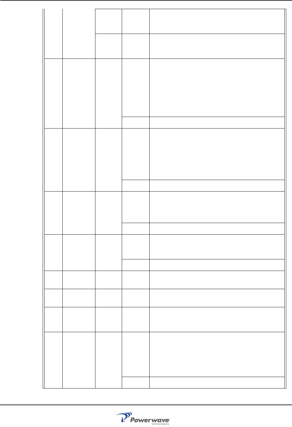
Troubleshooting AR Standard Repeater
4-6 044-05250 Rev A
BSC
R2R Error R2R HW failure because the CU cannot read the
MAC-ID or any other HW error in the R2R logic. Sug-
gested remedy: Replace the repeater.
FON
R2R
FO
Error R2R HW failure because the CU cannot read the
MAC-ID or any other HW error in the R2Rlogic. Sug-
gested remedy: Replace the FON PCBA.
60 Low traf-
fic activity RSSI
Statis-
tics
Warning No signal strength on the channel was above the limit
set longer than the time set in the configuration, indi-
cating possible problems with service antenna. The
area that the repeater is servicing may be covered by
another stronger repeater or BTS. Suggested rem-
edy: Ensure that the antennas and the cellular phone
work in the area to be covered, and that repeater sup-
ported channels are used.
Ceasing The cause of the alarm has ceased.
61 No BCCH
detected RSSI
Statis-
tics
Warning Signal strength on the BCCH channel was below the
limit set longer than the time set in the configuration,
indicating possible malfunction in the BTS or donor
antennas.
Suggested remedy: Ensure that the repeater is con-
figured to the BCCH channel and that the signal from
the BTS has enough strength.
Ceasing The cause of the alarm has ceased.
65 Gain
reduction Chan-
nel #,
UL/DL
Warning The gain is reduced below the limit.
The gain is reduced because the output power has
been above the MPC limit more than the preset limit
allows.
Ceasing The cause of the alarm has ceased.
66 Over-
power
alarm
Chan-
nel #,
UL/DL
Warning Input power too high, output power above maximum
limit.
Ceasing The cause of the alarm has ceased.
70 Bad table
alarm CU Error Requested table contains incorrect information (SW
error).
71 Table not
found CU Error Requested table not found in the database (SW or
calibration error).
72 Table
database
error
CU Error Table database not found (calibration error).
80 Antenna
SWR
alarm
Donor
antenn
a, ser-
vice
antenn
a
Error Too low antenna return loss, caused either by cables,
connectors, or antenna problems.
Suggested remedy: Check antenna and cables.
Ceasing The cause of the alarm has ceased.

AR Standard Repeater Troubleshooting
044-05250 Rev A 4-7
90 FON
power
alarm
FON
RF Error A DC voltage on a FON PCBA is out of range. Sug-
gested remedy: Replace the FON PCBA.
Ceasing The cause of the alarm has ceased.
91 FON
TxStable
alarm
FON
RF Error Laser transmitter control loop voltage out of range.
Suggested remedy: Replace the FON PCBA.
Creas-
ing The cause of the alarm has ceased.
92 FON
RxLevel
alarm
FON Warning Received optical level is below any of the two limits
(one for Warning and one for Error). Suggested rem-
edy: Check optical cables.
Error Received optical level is below any of the two limits
(one for Warning and one for Error). Suggested rem-
edy: Check optical cables.
Ceasing The cause of the alarm has ceased.
93 FON SPI
alarm FON
F2F Error The SPI bus connection to the RF modem does not
work properly. Suggested remedy: Replace the FON
PCBA.
97 No GPS
signal GPS Warning The GPS device cannot find any satellites. If active
antenna is used, then the power supply for it can be
faulty or wrongly configured. Suggested remedy:
Check the GPS antenna and cables. If an active
antenna is used, then the jumper switch should be set
accordingly.
Ceasing The cause of the alarm has ceased.
98 No GPS
device GPS Error The GPS device cannot be detected although an
adapter PCBA is mounted. Suggested remedy:
Check the GPS PCBA.
Ceasing The cause of the alarm has ceased.
99 GPS
Antenna
power
GPS Error The power supply to the GPS antenna is faulty or
there is a power supply to a passive antenna.
Suggested remedy: Check the GPS antenna and
cables. If an active antenna is used, then the jumper
switch should be set accordingly.
Ceasing The cause of the alarm has ceased.
100 Startup
error CHA # Error A hardware error is detected on the PCBA at power-
ing up.
101 Synthe-
sizer fault CHA # Error Unlocked synthesizer. The frequency synthesizer is
unlocked and the transmission can take place on an
unknown frequency.
102 Volt Reg.
fault CHA # Error DC voltage missing. A DC voltage to an analog part
of the PCBA is missing.
103 PA fault CHA # Error Low power amplifier gain. The PA PCBA has too low
output power for the RSSI and gain set. Not available
in all CU software versions.

Troubleshooting AR Standard Repeater
4-8 044-05250 Rev A
104 Param R/
W error CHA # Error EEPROM read or write failure on the PCBA.
105 High tem-
perature CHA # Warning The CHA PCBA temperature is higher than 85°C.
Error The CHA PCBA temperature is higher than 95°C.
Ceasing The CHA PCBA temperature has fallen below 70°C.
110 SW
incom-
patibility
MRX Error The MRX and CU software is not compatible.
Suggested remedy: Check the software versions and
replace the incompatible one.
120 Startup
error BSA # Error A hardware error is detected on the BSA PCBA at
powering up.
121 Synthe-
sizer fault BSA # Error Unlocked synthesizer.
The frequency synthesizer is unlocked and the trans-
mission can take place on an unknown frequency.
122 Volt Reg
fault BSA # Error A DC voltage to an analog part of the PCBA is miss-
ing.
123 PA fault BSA # Error Low power amplifier gain.
The PA PCBA has too low output power for the RSSI
and gain set. Not available in all CU software ver-
sions.
124 Param R/
W fault BSA # Error EEPROM read or write failure on the BSA PCBA.
125 High tem-
perature BSA # Warning The BSA PCBA temperature is higher than 85°C.
Error The BSA PCBA temperature is higher than 95°C and
the power is turned off.
Ceasing The temperature has fallen to below 70°C and the
power is turned on again.
126 High PSU
voltage BSA # Critical The PA supply voltage is too high.
Suggested remedy: Ensure that correct PSU is used.
127 Unsup-
ported
PA- type
BSA # Error The ID of the mounted PA PCBA is not expected by
the BSA PCBA. Suggested remedy: Ensure that cor-
rect PA PCBA is used.
128 BA HW
alarm BA # Error A HW error on the BA PCBA has been detected.
Ceasing The BA PCBA is working properly after failure.
129 PA Under-
voltage
alarm
PA/BA
#Error PA voltage level below alarm limit. Suggested rem-
edy: Check the PSU.
Ceasing The cause of the alarm has ceased.
BSC,
UL/DL Error PA voltage level below alarm limit. Suggested rem-
edy: Check the PSU.
Ceasing The cause of the alarm has ceased.
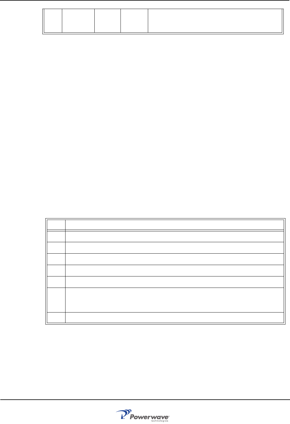
AR Standard Repeater Field Replaceable Units
044-05250 Rev A 4-9
Remarks: The Door open alarm requires an optional door switch described in the P33 Alarm Port section in
Chapter 3.
The Main Power Breakdown alarm requires a relay not included in the repeater (see Main Power
Breakdown Relay in Chapter 3).
Channel #, UL/DL Repeater channel number (1-4) at CSel operation, uplink or downlink.
BSEL #, UL/DLRepeater channel number at BSel operation, uplink or downlink.
BA #, BA PCBA number for high power operation.
BSA #, BSA PCBA number for BSel operation.
CHA #, CHA PCBA number for CSel operation.
CSA #, CSA PCBA number for CSel CDMA operation.
FON, FON PCBA for fiber optic communication.
PA, PA PCBA for CSel or BSel operation.
Field Replaceable Units
The following units can be replaced in the field on-site by a qualified technician with
experience maintaining RF equipment:
• FON
• PSU
• AR Repeater
FON
To replace a FON PCBA, proceed as described in the Table 4-3.
Table 4-3 FON Replacement Procedure
245 Not In
Allowed
Area
CU None Repeater is moved from the operating area and the
RF HW is switched on or off.
Step Action
1 Open repeater door and secure
2 Locate power connector on FON and remove connector from PCBA
3 Verify all cables on FON are labeled before disconnecting, then disconnect all cables
4 Remove screws securing FON PCBA to FOU and remove PCBA
5 Replace FON PCBA in reverse order and apply power
6 Connect PC to OM Online port, login to FON and verify configuration and IP address.
NOTE: Make sure ‘Fiberoptical’ classmark in the FON Status window is checked, other-
wise FON will not be operational.
7 Close repeater door and secure
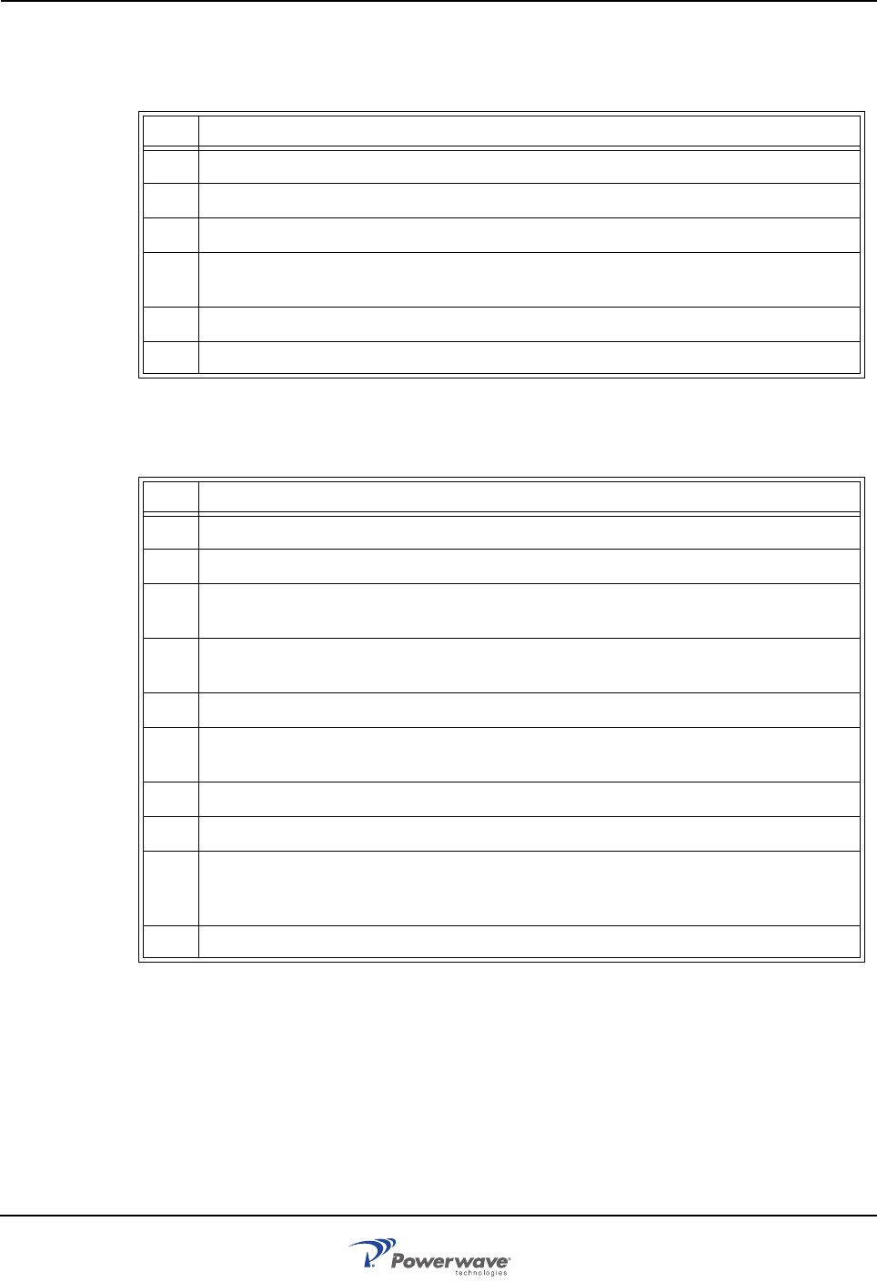
Field Replaceable Units AR Standard Repeater
4-10 044-05250 Rev A
PSU
To replace a PSU, proceed as described in the Table 4-4.
Table 4-4 PSU Replacement Procedure
Repeater
To replace an AR repeater, proceed as described in the Table 4-5.
Table 4-5 Repeater Replacement Procedure
Step Action
1 Open repeater door and secure
2 Disconnect main power plug from PSU
3 Disconnect power cable bundle from PSU
4 Loosen screws securing PSU using a 5mm Allen key and remove.
NOTE: screws are designed to not be removed completely from PSU.
5 Replace PSU in reverse order and apply power
6 Close repeater door and secure
Step Action
1 Open repeater door and secure
2 Disconnect main power plug from PSU
3 Verify all cables connected to repeater are labeled before disconnecting, then disconnect
all cables
4 Remove mounting screws from bottom legs of repeater and loosen mounting screws in
top legs
5 Close and secure door
WARNING: A fully loaded AR Repeater can weigh 75lbs. Lifting of the repeater should be
done by two people. Do not attempt to carry the repeater up a ladder.
6 Lift the repeater off the mount hinges
7 Replace repeater in reverse order
8 Connect PC to OM Online port and verify configuration. For Fiber Optic installations, ver-
ify IP address. NOTE: Make sure ‘Repeater On’ classmark in the BSEL Status window is
checked, otherwise the repeater will not be operational.
9 Close repeater door and secure
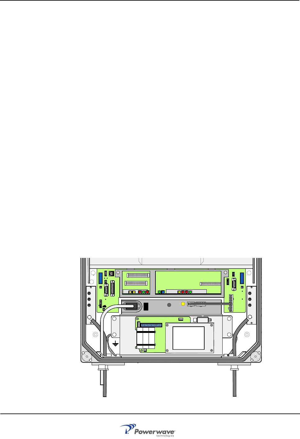
AR Standard Repeater Return For Service Procedures
044-05250 Rev A 4-11
Return For Service Procedures
When returning products to Powerwave, the following procedures will ensure optimum
response.
Obtaining an RMA
A Return Material Authorization (RMA) number must be obtained prior to returning equipment
to the factory for service. Pease contact our Repair Department at 1-714-466-1000 to obtain
this number, or FAX your request to 1-714-466-5800. Failure to obtain this RMA number may
result in delays in receiving repair service.
Repackaging for Shipment
To ensure safe shipment of the unit, it is recommended that the original package designed for
shipping the unit be reused. If it is not available, contact Powerwave’s Customer Service
Department for packing materials.
Options
This chapter describes the following optional accessories available for the Powerwave
repeaters:
• Remote Control Unit (RCU) including the old RCU for GSM 900/1800/1900
• Repeater To Repeater Link (R2R)
• Traffic Statistics
• Battery Backup
• 7/16” Antenna Cable Connectors
• Operation and Maintenance System (OMS)
Remote Control Unit (RCU)
The RCU provides remote control of Powerwave repeaters. It contains an integrated mobile
phone, modem and power supply backup. The RCU is installed in the bottom front of the
cabinet, on top of the PSU as illustrated in Figure 4-1.
Figure 4-1 RCU Location
MS
DPX
ANT
TEST
DC
-30 dB
-20 dB MS
DPX
ANT
TEST
DC
-30 dB
-20 dB
ALLGON INNOV ATION
SWEDEN M105 R6
1
PARKING
FOR W 5
W5
8
P27 W6B 10
1
P33
ALARM
P23
LNA
UP-LINK
P32
MODEM
AUX1
P28
DOOR
5
9
61
116
1
1
M->S
P11
P34
8
9
15
P26
15 16
S->M
12
389
P36
5
X0A
X0B
2V2 116
P12 P13
1
1
1
16
16
16
P4
P5
P6
c
b
a
c
b
a
c
b
a
c
b
a
1P232
1
b
a
116P3
16 116
P14
1
V1
1
1
1
1
1
4
6
1
15
6
915
2
16
1
2
4
5
8
5
P35
P21
PSU
6
10
P31
PC
P29
P24
P25
GND
7
6V6
LNA
DOWN- LINK
LED
P22
1
2
POWER SUPPLY UNIT
RCU
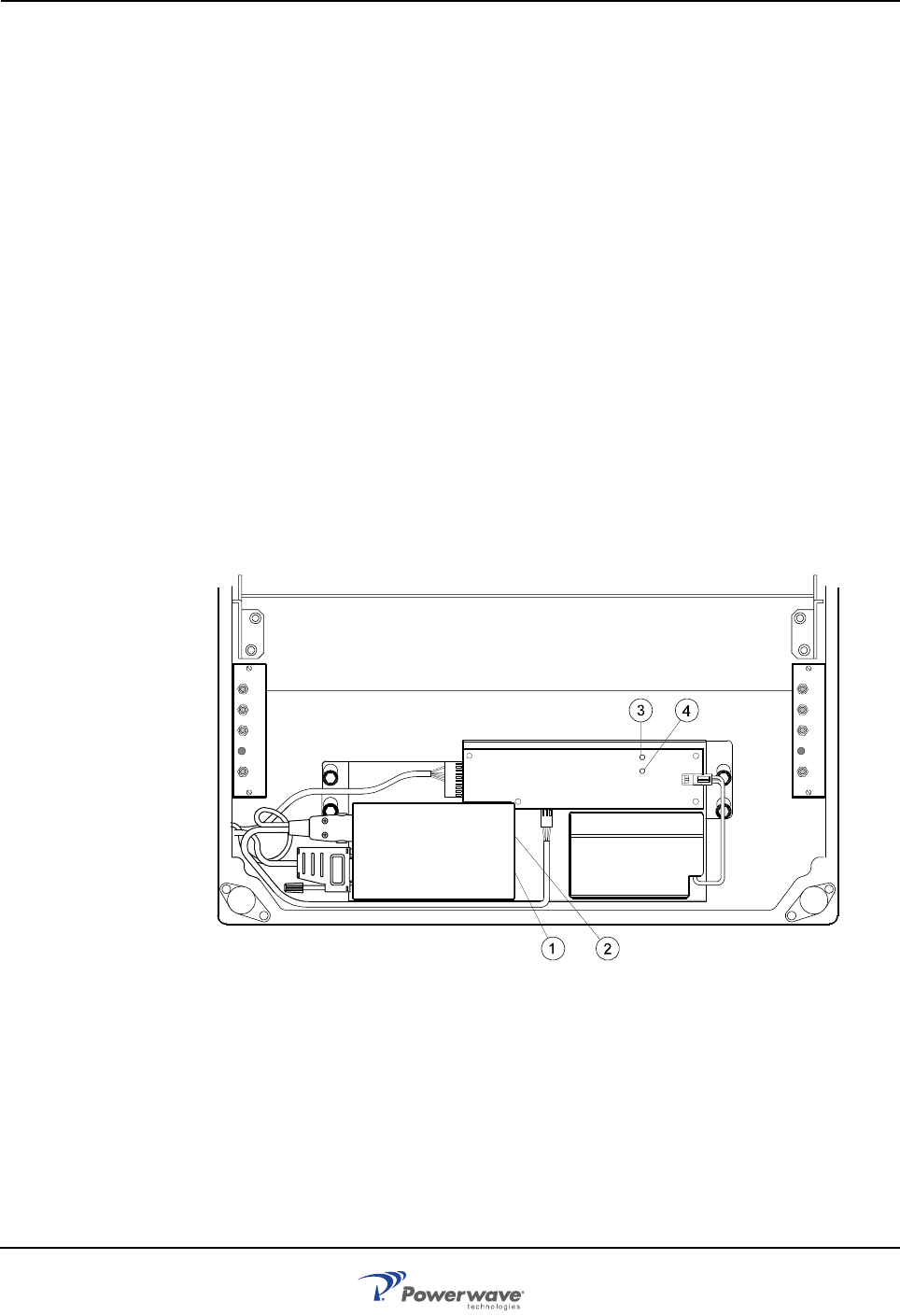
Options AR Standard Repeater
4-12 044-05250 Rev A
The RCU is connected to P130 on either an RCI or FON. A jumper is required between pins 1
and 2 on the RCI if the P130 cable connector is disconnected. If a main power failure occurs,
the unit has a battery with enough capacity for sending a number of alarms.
Previous RCU versions have been replaced by the current type. The repeaters are
compatible with the previous version. Differences apply to the connections of the previous
version where data was transferred between the repeater and the RCU via the P32 modem
port on the DIA and was powered via the P27 auxiliary port on the DIA.
RCU for Radio Communication
The RCU antenna for a radio modem is connected to the BS antenna via the uplink DC,
provided the RCU and the repeater operate in the same cell system. Otherwise, the modem
must have a separate antenna. Data is transferred between the repeater and the RCU via the
P130 modem port on the RCI or FON. The RCU is also powered via the same port and has a
battery with enough capacity to send a number of alarms if a main power failure occurs.
RCU for Telephone Line Communication
The land line version uses a telephone line connected to a terminal block on the RCU. A free
strain relief bushing at the bottom of the repeater is used for the external telephone line cable.
Previous RCU Version for GSM 900/1800/1900
This description is for reference use only. This RCU is replaced by the current version and
consists of an integrated mobile phone/modem, power supply and power supply backup. It
was located inside the repeater cabinet, in front of the PSU as illustrated in Figure 4-2.
Figure 4-2 RCU – GSM 900 type
The RCU was connected to P27, P32, and the MS -20dB port. The following callout numbers
refer to the numbers in Figure 4-2.
1. The GSM PCBA. Press a pencil or similar object on the small button adjacent to the SIM
PCBA to release it.
2. The LED indicator on the phone/modem unit that shows three operational modes:
Out:The unit is off
Slow flashing: Stand by
12volt 0.7Ah
MS
DPX
ANT
TEST
DC
-30 dB
-20 dB
MS
DPX
ANT
TEST
DC
-30 dB
-20 dB
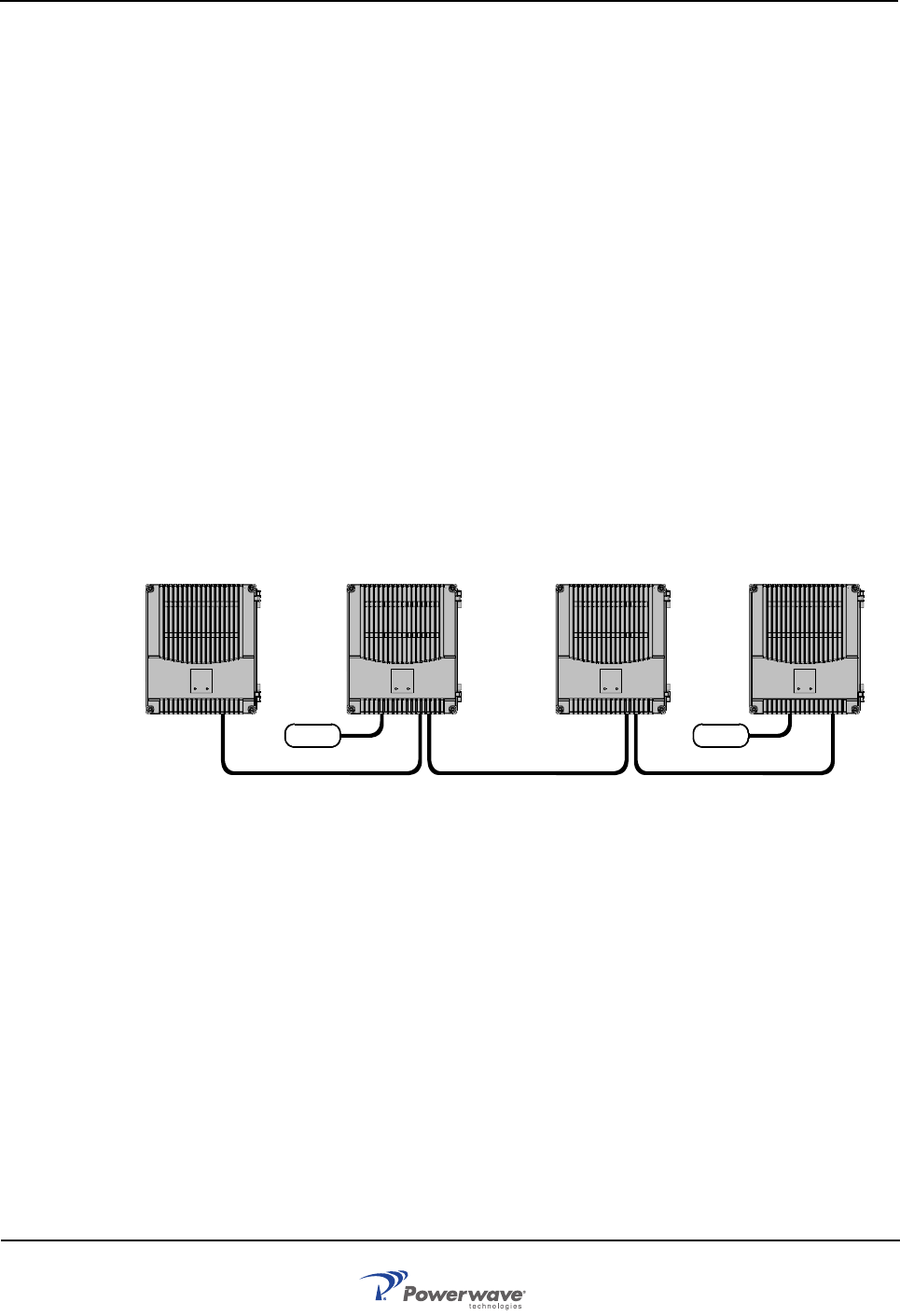
AR Standard Repeater Options
044-05250 Rev A 4-13
Fast flashing:Connection in progress
3.Green LED on the battery charger which is lit steady when the power supply is OK either
from the main input power or from the battery.
4.Yellow LED on the battery charger which is lit steady during battery charge from the main
input power.
A jumper is required between pins 2 and 3 on the P27 connector if the RCU is disconnected
from the DIA.
GSM subscriber conditions
Data rate = 9600 bps, transparent mode. If the PIN code has to be disabled, use another
phone. If you encounter problems with the PIN code, contact Powerwave Technical Support.
Power supply backup
If a power failure occurs the backup battery has capacity to supply the CU, ALI and phone/
modem for 30 minutes at room temperature and a limited number of call attempts. The
battery life is 1 - 2 years at normal indoor temperature. If the operational temperature is
higher, the battery life is shortened.
Repeater-to-Repeater Link (R2R)
This section briefly describes the R2R network. Node configuration for the R2R network is
described in the OM-Online User’s Manual.
Figure 4-3 R2R network
The R2R network is a Powerwave specific repeater network that can handle up to 13 nodes,
one or several of which being gateway repeaters for communication with OM-Online or OMS
via modem. Powerwave repeaters produced after January 2005 have the R2R functionality.
Repeaters produced prior to this date can be upgraded with an R2R network kit provided the
repeaters meet the following requirements:
Hardware
DIA PCBAK105/1 version R2A or higher
RIA PCBAThe RIA PCBA is required if the K105/1 DIA PCBA has a version
lower than R3A.
CU PCBAK103/2 version R1A or higher
Software
CUSA102 02/1 version R3A or higher
Information for upgrades is located in the R2R, Repeater to Repeater Link Kit, Installation
Guide. (part # VD202 91/EN).
PSTNPSTN

Options AR Standard Repeater
4-14 044-05250 Rev A
Protocol
Sliding Window (SLW) is a Powerwave specific protocol developed for the R2R network. The
SLW protocol and the IP protocol do not support each other and they cannot be mixed in any
node.
Traffic Statistics
Traffic statistics are available for channel selective EDGE/GSM 900, GSM 1900 and DCS/
PCN 1800 repeaters, provided the repeaters have the latest CU software version, the latest
CU and CHA PCBAs, and an OMS is used to poll and view the statistics.
Battery Backup (BBU)
Battery backup is available with a Powerwave BBU battery backup. The BBU has an exterior
similar to the repeater.
7/16" Antenna Cable Connectors
A 7/16" antenna cable kit is available for all the Powerwave repeaters. This kit includes 7/16"
antenna connectors for UL and DL antennas mounted on two repeater cable inlet flanges and
cables and connectors for connection to the DCs inside the repeater.
Operation and Maintenance System (OMS)
OMS is a Powerwave software package for repeater fleet management. Multiple modems
can be used for several incoming and outgoing parallel activities, such as alarm reception,
radio parameter configuration and software downloading.
OMS has also ability to schedule activities.

044-05250 Rev A 5-1
Chapter 5
Specifications
Introduction
This chapter provides specifications for the AR Standard Repeater product line.
Table 5-1 AR Standard Repeater Specifications
Generic
Dimensions (W x H x D in inches) 17.5 x 21 x 7 (low cover)
17.5 x 21 x 11 (high cover)
Weights:
Empty low cover
Repeater with a low cover
Combined repeater with a high cover
Equipped cabinet or high cover w/extra heat sink element
13 lbs (6.0 kg)
50 lbs (22.5 kg)
82 lbs (37.0 kg)
41 lbs (18.5 kg)
Temperature range -13 to +131°F (-25 to + 55°C)
Casing class NEMA4/IP65
Fiber Optic Link Budget 15dBo
Amplifiers in 1 cabinet Standard = 2; High Power = 4
Receiver input port return loss 14dB
Power supply voltage (default) 115 VAC
Power consumption, max 160 W
AR1200 Family - GSM 900 Band Selective
Frequency band UL 890-915 MHz
Frequency band DL 935-960 MHz
Number of channels N/A
Absolute group delay 6 µs
Filter bandwidth (remotely adjustable) 0.5-16.9 MHz, remote adjustable
Gain adjustment range (in 1 dB steps) 45-85dB
Gain (max variation –25 to +55 °C) 6dB
Pass band ripple 4dB
Maximum input power (non-destructive) +13dBm
Output power RMS, one carrier, DL +26dBm (+29dBm PEP)
Noise figure at 85 dB gain, 25° C (typical) 6dB
Introduction AR Standard Repeater
5-2 044-05250 Rev A
AR1700 Family - GSM 900 Channel Selective
Frequency band UL 890-915 MHz
Frequency band DL 935-960 MHz
Number of channels 1 to 8
Absolute group delay 5 µs
Filter bandwidth (remotely adjustable) 200 KHz
Gain adjustment range (in 1 dB steps) 55-90dB
Gain (max variation –25 to +55 °C) 4dB
Pass band ripple 3dB
Maximum input power (non-destructive) +13dBm
Output power RMS, one carrier, DL +33dBm
Noise figure at 85 dB gain, 25° C (typical) 4dB
AR2100/2700 Family - GSM 1800 Channel Selective
Frequency band UL 1710-1785 MHz
Frequency band DL 1805-1880 MHz
Number of channels 1 to 8
Absolute group delay 5 µs
Filter bandwidth (remotely adjustable) 200 KHz
Gain adjustment range (in 1 dB steps) 55-90dB
Gain (max variation –25 to +55 °C) 4dB
Pass band ripple 3dB
Maximum input power (non-destructive) +13dBm
Output power RMS, one carrier, DL +32dBm
Noise figure at 85 dB gain, 25° C (typical) 4dB
AR2200 Family - GSM 1800 Band Selective
Frequency band UL 1710-1785 MHz
Frequency band DL 180-1880 MHz
Number of channels N/A
Absolute group delay 6 µs
Filter bandwidth (remotely adjustable) 0.5-16.9 MHz, remotely adjustable
Gain adjustment range (in 1 dB steps) 45-85dB
AR Standard Repeater Introduction
044-05250 Rev A 5-3
Gain (max variation –25 to +55 °C) 6dB
Pass band ripple 5dB
Maximum input power (non-destructive) +13dBm
Output power RMS, one carrier, DL +29dBm (+32dBm PEP)
Noise figure at 85 dB gain, 25° C (typical) 6dB
AR3100/3700 Family - GSM 1900 Channel Selective
Frequency band UL 1850-1910 MHz
Frequency band DL 1930-1990 MHz
Number of channels 1 to 8
Absolute group delay 5 µs
Filter bandwidth (remotely adjustable) 200 KHz
Gain adjustment range (in 1 dB steps) 55-90dB
Gain (max variation –25 to +55 °C) 4dB
Pass band ripple 3dB
Maximum input power (non-destructive) +13dBm
Output power RMS, one carrier, DL +32dBm
Noise figure at 85 dB gain, 25° C (typical) 4dB
AR3400 Family - GSM 1900 Band Selective
Frequency band UL 1710-1785 MHz
Frequency band DL 1805-1880 MHz
Number of channels N/A
Absolute group delay 6 µs
Filter bandwidth (remotely adjustable) 0.5-16.8 MHz, remotely adjustable
Gain adjustment range (in 1 dB steps) 45-85dB
Gain (max variation –25 to +55 °C) 6dB
Pass band ripple 5dB
Maximum input power (non-destructive) +13dBm
Output power RMS, one carrier, DL +33dBm (+36dBm PEP)
Noise figure at 85 dB gain, 25° C (typical) 6dB
Introduction AR Standard Repeater
5-4 044-05250 Rev A
AR1700/902 Family - EGSM 900 Channel Selective
Frequency band UL 880-915 MHz
Frequency band DL 925-960 MHz
Number of channels 1 to 8
Absolute group delay <5 µs
Gain adjustment range (in 1 dB steps) 55-90dB
Gain (max variation –25 to +55 °C) 4dB
Pass band ripple 1dB
Maximum input power (non-destructive) +13dBm
Output power RMS, one carrier, DL +33dBm
Noise figure at 85 dB gain, 25° C (typical) 4dB
AR1100/802 Family - RGSM 900 Channel Selective
Frequency band UL 876-880 MHz
Frequency band DL 921-925 MHz
Number of channels 1 to 4
Absolute group delay <5 µs
Gain adjustment range (in 1 dB steps) 55-90dB
Gain (max variation –25 to +55 °C) 4dB
Pass band ripple 1dB
Maximum input power (non-destructive) +13dBm
Output power RMS, one carrier, DL +33dBm
Noise figure at 85 dB gain, 25° C (typical) 4dB
AR6500 Family - WCDMA Channel Selective
Frequency band UL 1920-1980 MHz
Frequency band DL 2110-2170 MHz
Number of channels 1 to 2
Absolute group delay 6 µs
Filter bandwidth (remotely adjustable) 5 MHz
Gain adjustment range (in 1 dB steps) 60-90dB
Gain (max variation –25 to +55 °C) 4dB
Pass band ripple 2dB within 4 MHz

AR Standard Repeater Introduction
044-05250 Rev A 5-5
Maximum input power (non-destructive) +13dBm
Output power RMS, one carrier, DL +30dBm; Standard AR6500
Output power RMS, one carrier, UL +20dBm
Output power RMS, one carrier, DL +38dBm; High Power AR6560
Noise figure at 85 dB gain, 25° C (typical) 3dB
AR3400 Family – TDMA/CDMA Band Selective
Frequency band UL 1850-1910 MHz
Frequency band DL 1930-1990 MHz
Absolute group delay 6 µs
Filter bandwidth (remotely adjustable) 0.5-16.9 MHz
Gain adjustment range (in 1 dB steps) 45-85dB
Gain (max variation –25 to +55 °C) 6dB
Pass band ripple 5dB
Maximum input power (non-destructive) +13dBm
Output power RMS, one carrier, DL +33dBm (+36dBm PEP)
Output power RMS, one carrier, UL +33dBm (+36dBm PEP)
Output power RMS, one carrier, DL +36dBm (+39dBm PEP) AR4240
Noise figure at 85 dB gain, 25° C (typical) 6dB
AR4200 Family – AMPS Band Selective
Frequency band UL 824-849 MHz
Frequency band DL 869-894 MHz
Absolute group delay 6 µs
Filter bandwidth (remotely adjustable) 0.5-16.9 MHz
Gain adjustment range (in 1 dB steps) 45-85dB
Gain (max variation –25 to +55 °C) 6dB
Pass band ripple 5dB
Maximum input power (non-destructive) +13dBm
Output power RMS, one carrier, DL +33dBm (+36dBm PEP) AR4200
Output power RMS, one carrier, UL +33dBm (+36dBm PEP)
Output power RMS, two carrier, DL +36dBm (+39dBm PEP) AR4240
Noise figure at 85 dB gain, 25° C (typical) 6dB
Introduction AR Standard Repeater
5-6 044-05250 Rev A
AR4600 Family – iDEN/SMR Band Selective
Frequency band UL 806-824 MHz
Frequency band DL 851-869 MHz
Absolute group delay 6 µs
Filter bandwidth (remotely adjustable) 0.5-16.9 MHz
Gain adjustment range (in 1 dB steps) 45-85dB
Gain (max variation –25 to +55 °C) 6dB
Pass band ripple 5dB
Maximum input power (non-destructive) +13dBm
Output power RMS, one carrier, DL +33dBm (+36dBm PEP) AR4200
Output power RMS, one carrier, UL +33dBm (+36dBm PEP)
Output power RMS, two carrier, DL +36dBm (+39dBm PEP) AR4240
Noise figure at 85 dB gain, 25° C (typical) 6dB
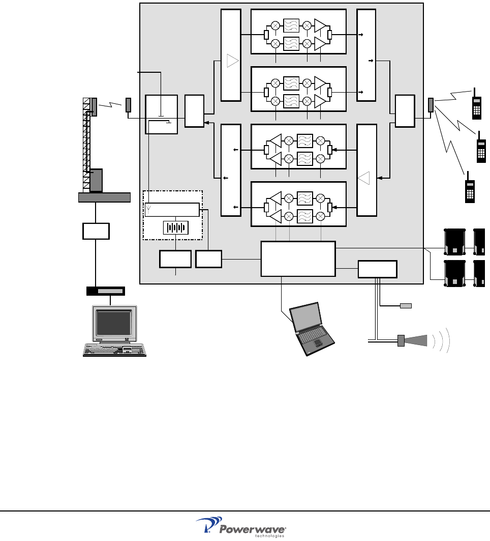
044-05250 Rev A A-1
Appendix A
Block Diagrams
Introduction
This appendix describes the main signals paths for the different AR Standard Repeater
models.
CSel GSM Repeater
Figure A-1 CSel GSM Repeater Block Diagram
Figure A-1 illustrates a block diagram of a CSel repeater with four bi-directional channels.
This diagram is applicable to repeaters for the GSM, DCS, and PCS systems.
The signal from the base station is received via the repeater donor antenna and then
forwarded through a DC, used as an antenna port only if an RF modem is used. The signal
passes a DPX, is amplified in a LNA, and enters the CHEs which have two parallel channels
each. The first mixer stage on the CHE, which is controlled by a synthesizer, converts the
received frequency down to the IF frequency. The signal is then filtered by SAW bandpass
filters and amplified before it is fed to the second mixer stage for conversion back to the
original frequency.
DC
BS
P31 P33
TEST –30 dB
CHE1 - DL
CHE2 - DL
CHE3 - UL
CHE4 - UL
DPX
LNA
DL CMB
DL
MS –20 dB
DPX
ALI / RCI
CU
WLI
P34/
P36
P130 P130
ANT DPX ANT HI
LO
HI
LO
IN
OUT2
OUT1
P101 P701
P101 P701
ANT
P101
P101
P701
P701
LNA
UL
IN
OUT1
OUT2
CMB
UL
RCU
PSU RCI
MSC
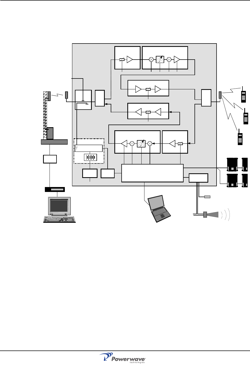
CSel CDMA/WCDMA Repeater AR Standard Repeater
A-2 044-05250 Rev A
The output signal from the mixer is then amplified in the PA and fed to a combiner which
combines the signals from the two channels on the CSA The output signal passes a CMB and
DPX before it is fed to the repeater service antenna.
CSel CDMA/WCDMA Repeater
Figure A-2 CSel CDMA/WCDMA Repeater Block Diagram
Figure A-2 illustrates a block diagram of a CSel CDMA or WCDMA repeater. The signal from
the base station is received via the repeater donor antenna and is forwarded through a DC,
used as antenna port only if an RF modem is used. The signal passes a DPX, is amplified in
a LNA, and enters the CSA which has two parallel channels.
The first mixer stage on the CSA, which is controlled by a synthesizer, converts the received
frequency down to the IF frequency. The signal is then filtered by SAW bandpass filters and
amplified before it is fed to the second mixer stage for conversion back to the original
frequency. The following amplifier on the CSA is controlled by the CU. The output gain can be
reduced to avoid instability due to poor antenna isolation by means of a gain control in the
CU. The gain control also affects other amplification stages. The output signal from the
amplifier is fed to a combiner which combines the signals from the two channels on the CSA.
The signal from the CSA is amplified on the PA and then fed to a DPX or, in high power
CDMA repeaters, to a BA. The amplified output signal passes the DPX before it is fed to the
repeater service antenna.
In high power CDMA or WCDMA repeaters, a BA boosts the output DL signal from the PA by
typically 6dB. The amplified signal is fed to the DPX at the service port. Only the DL path has
a BA which is powerwed by a second PSU.
DC
BS
P130
P31 P33
TEST –30 dB
BSA - DL
PA - DL
LNA - DL
MS –20 dB PA - UL
BSA - UL LNA - UL
DPX
DPX
ALI / RCI
WLI
P34/
P36
CU
P130
ANT DPX ANT HI
LO ANT
HI
LO
IN OUT1 P101 P301
P4 P5
IN
IN
OUT1
P301 P101
P4P5
RCU
PSU RCI
MSC
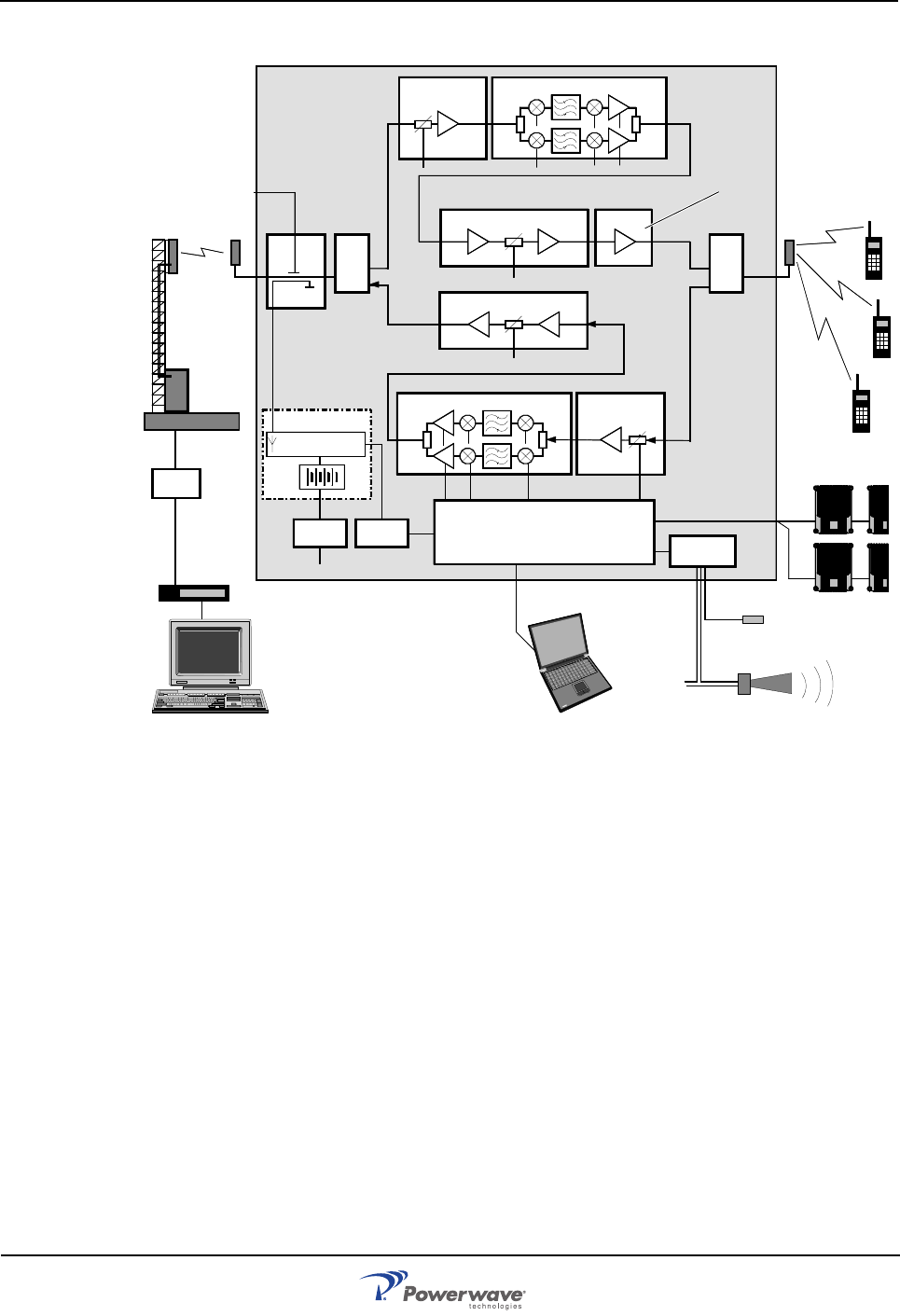
AR Standard Repeater BSel Repeater
044-05250 Rev A A-3
BSel Repeater
Figure A-3 BSel Repeater Blcok Diagram
Figure A-3 illustrates a block diagram of a BSel repeater. This diagram is applicable to
repeaters for e.g. GSM, TACS, ETACS, AMPS, DAMPS, CDMA and WCDMA systems. The
signal from the base station is received via the repeater donor antenna and is then forwarded
through a DC, used as antenna port only if an RF modem is used. The signal passes a DPX,
is amplified in a LNA, and enters the BSA.
The first mixer stage on the BSA, which is controlled by a synthesizer, converts the received
frequency down to the IF frequency. The signal is then filtered by SAW bandpass filters and
amplified before it is fed to the second mixer stage for conversion back to the original
frequency. The BSA has adjustable bandwidth and the SAW filter combination can be
software changed from OM-Online (or OMS).
The following PA is controlled by the CU. The amplifier gain will be reduced to avoid instability
due to poor antenna isolation. A detector on the PA measures the output level continuously.
The signal from this detector is used by the automatic gain control (AGC) to supervise and, if
necessary, reduce the output power to keep it under a maximum level. The AGC also affects
other amplification stages.
The output signal from the PA at P5 passes a DPX before it is fed to the repeater service
antenna.
MS –20dB
DC
BS
P130
P31 P33
TEST –30 dB
PA - DL
LNA - DL
PA - UL
LNA - UL
CSA - DL
DPX
CSA - UL
ALI / RCI
P130
DPX
BA
ANT DPX HI
LO
ANT ANT
HI
LO
IN OUT1 P101 P301
P4 P5 P3 P4
IN
OUT1
P101
P301
P4P5
MS –20 dB
RCU
RCI
PSU
MSC WLI
P34/
P36
CU
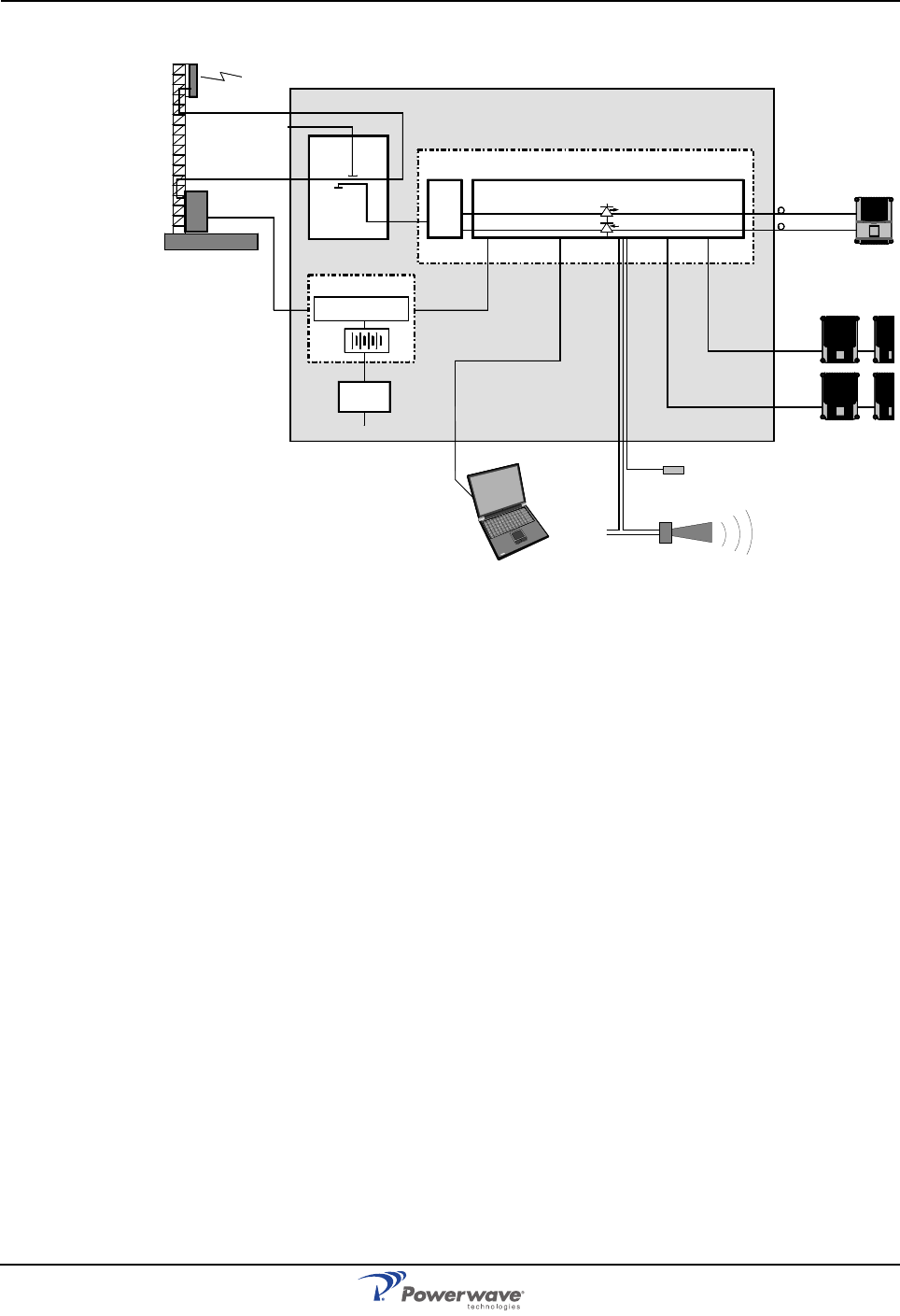
BMU AR Standard Repeater
A-4 044-05250 Rev A
BMU
Figure A-4 BMU Block Diagram
Figure A-4 illustrates a block diagram of a BMU. The BMU has to be located adjacent to the
BTS as the base station antenna signal passes through the BMU. Features controlled by the
CU, ALI and RCI PCBAs in standard repeaters are controlled here by the FON which has the
required functionality and the FLI function built-in.
The base station antenna signal is fed through a DC inside the BMU. The signal from the MS
-20dB port enters the FOU by passing a DPX. The downlink path (HI) is then fed to the FON
which converts the RF signal to an optic signal. The optical signal from the TX output is sent
via fiber optic cables to a FOR.
DC
BS
TEST –30 dB
MS –20 dB
ANT DPX
FON
TX
RX
DPX
ANT HI
LO
FOU
FOR
WRH
BTS
P130
RCU
PSU
P111 P112P130 P109P106
P101
P102
FLI
WLI
WLI
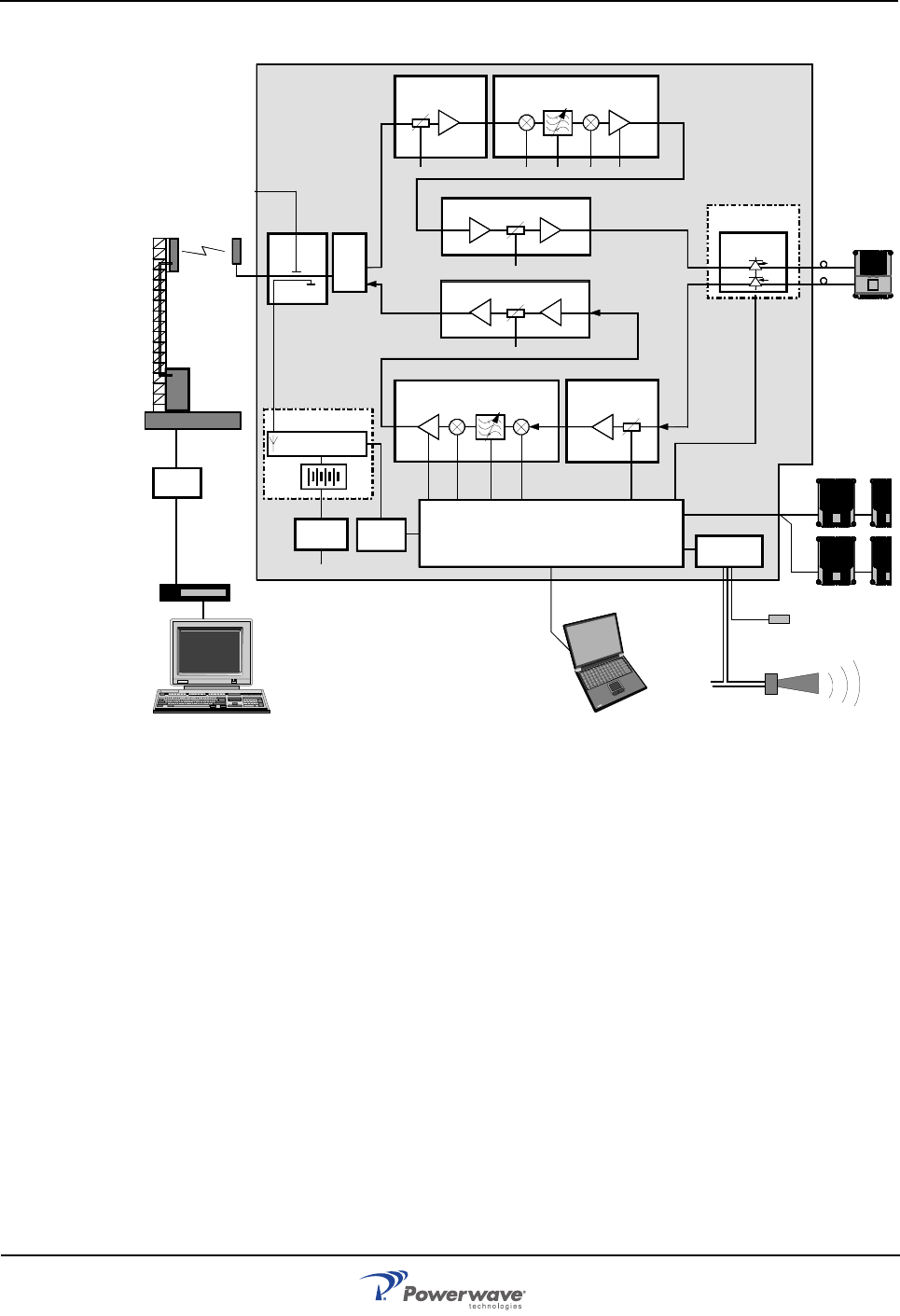
AR Standard Repeater RMU
044-05250 Rev A A-5
RMU
Figure A-5 RMU Block Diagram
Figure A-5 illustrates a block diagram of an RMU for band selective operation. This diagram
is identical to the block diagram of the band selective repeater except for the FOU and the
fiber optic connection to a FOR.
The output signal from the PA at P5 enters the FON which converts the RF signal to an
optical signal. The FON supervises the signaling and reports errors via the RCU connected to
the CU. The optical signal from the TX output is sent via a fiber optic cable to a FOR.
FON
P101 TX
RX
P102
FOU
MSC
DC
BS
P130
P31 P33
TEST –30 dB
BSA - DL
PA - DL
LNA - DL
MS –20 dB PA - UL
BSA - UL LNA - UL
DPX
ALI / RCI
WLI
P34/
P36
P130
ANT DPX ANT HI
LO
IN OUT1 P101 P301
P4 P5
IN
IN
OUT1
P301 P101
P4P5
RCU
PSU RCI
FOR
CU
FLI
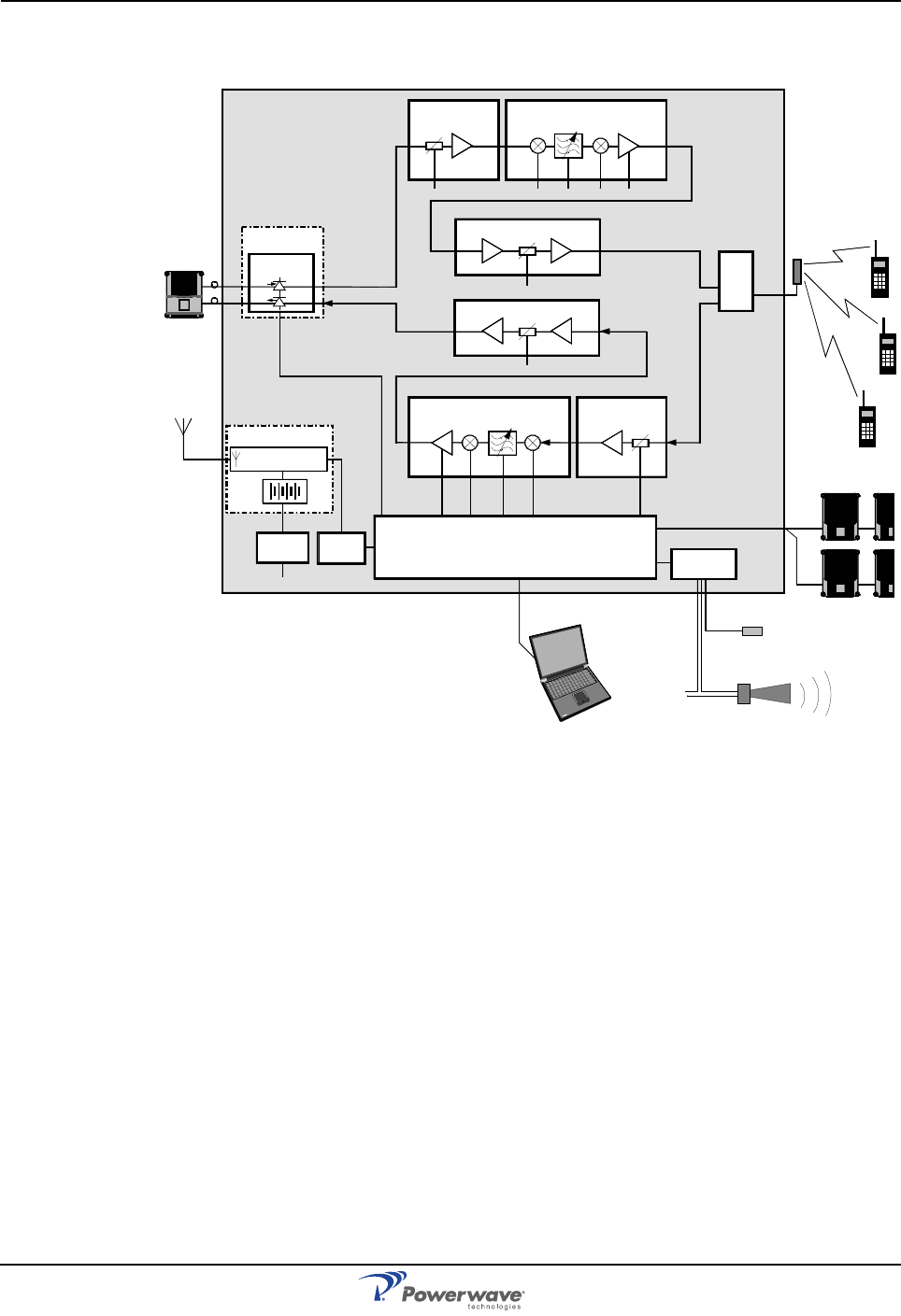
FOR AR Standard Repeater
A-6 044-05250 Rev A
FOR
Figure A-6 FOR Block Diagram
Figure A-6 illustrates a block diagram of a FOR with band selective operation. The diagram is
identical to the block diagram of the band selective repeater except for the FOU and the fiber
optic connection to the BMU, RMU or FOR.
The signal from a BMU, RMU or FOR is received via a fiber optic cable and is fed to the FON
on the FOU. The FON converts the optic signal to an RF signal, supervises the signaling and
reports errors via the RCU connected to the CU. The RF signal is then fed to the DL LNA.
FOU
FON
P102RX
TX P101
P130
P31 P33
BSA - DL
PA - DL
LNA - DL
PA - UL
BSA - UL LNA - UL
DPX
ALI / RCI
WLI
P34/
P36
CU
P130
ANT
HI
LO
IN OUT1 P101 P301
P4 P5
IN
IN
OUT1
P301 P101
P4P5
RCU
PSU RCI
BMU
RMU
FLI

C
orporate Headquarters
P
owerwave Technologies, In
c.
1
801 East St. Andrew Place
S
anta Ana, CA 92705 USA
T
el: 714-466-1000
F
ax: 714-466-5800
w
ww.powerwave.co
m
M
ain European Offic
e
A
ntennvägen 6
S
E-187 80 Täby
S
weden
T
el: +46 8 540 822 00
Fax: +46 8 540 823 40
M
ain Asia-Pacific Office
2
3 F Tai Yau Building
1
81 Johnston Road
W
anchai, Hong Kong
T
el: +852 2512 6123
Fax: +852 2575 4860
©Copyright March 2005, Powerwave Technologies, Inc. All Rights reserved. Powerwave, Powerwave Technologies, The Power in Wireless and the Powerwave logo are registered trademarks of Powerwave Technologies, Inc.
Powerwave Installation and Service Manual