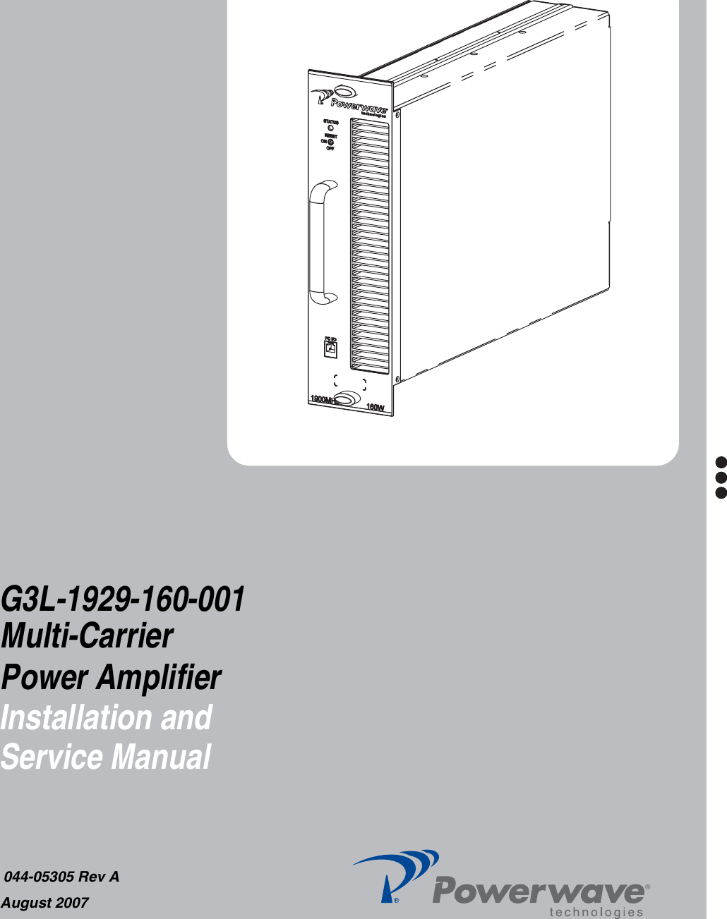
Powerwave Technologies 5JS0095 Multi-Carrier Power Amplifier User Manual 044 3505 Rev A G3L 1929 160 001

Powerwave Technologies Inc Multi-Carrier Power Amplifier 044 3505 Rev A G3L 1929 160 001

Users Manual

G3L-1929-160-001 Installation and Service Manual044-05305 Rev AAugust 2007Multi-CarrierPower Amplifier
© 2007 Powerwave Technologies Incorporated. All rights reserved.Powerwave Technologies, and the Powerwave logo are registered trademarks.This Powerwave product is intended only for installation in a RESTRICTED ACCESS LOCATION andthis Powerwave product is designed to operate within the normal operating (typical operating) rangesor conditions specified in this document. Operation of this equipment beyond the specified ranges inthis document may cause: 1. Spurious emissions that violate regulatory requirements.2. The equipment to be automatically removed from service when maximum thresholds are exceeded.3. The equipment to not perform in accordance with its specifications. It is the operator’s responsibility of the operator to ensure this equipment is properly installed andoperated within Powerwave operating specifications to obtain proper performance from the equipmentand to comply with regulatory requirements.For PERMANENTLY CONNECTED EQUIPMENT, a readily accessible disconnect device shall beincorporated in the building permanent wiring.
044-05305 Rev A iWarnings, Cautions, and NotesWarnings, Cautions, and Notes are found throughout this manual where applicable. The associated icons are used to quickly identify a potential condition that could result in the consequences described below if precautions are not taken. Notes clarify and provide additional information to assist the user.WARNING: This warning symbol means danger. You are in a situation that could cause bodily injury or death. Before working on any equipment, be aware of the hazards involved with electrical and RF circuits and be familiar with standard practices for preventing acci-dents.CAUTION: The caution symbol means reader be careful. In this situation, the user might do something that could result in equipment damage or loss of data. NOTE The note symbol means reader take note. Notes contain helpful suggestions or references to material not covered in this document. Procedures are not contained in notes.
ii 044-05305 Rev ARevision Record Revision Letter  Date of Change Reason for ChangeA Aug 2007 Initial Release
044-05305 Rev A iiiTable of Contents Chapter 1 - Product Description Introduction . . . . . . . . . . . . . . . . . . . . . . . . . . . . . . . . . . . . . . . . . . . . . . . . . . . . . . . . . . . . . . . . . . . . . . . . . . .1-1Scope of Manual . . . . . . . . . . . . . . . . . . . . . . . . . . . . . . . . . . . . . . . . . . . . . . . . . . . . . . . . . . . . . . . . . . . . . . .1-1Product Description . . . . . . . . . . . . . . . . . . . . . . . . . . . . . . . . . . . . . . . . . . . . . . . . . . . . . . . . . . . . . . . . . . . . .1-1Functional Description . . . . . . . . . . . . . . . . . . . . . . . . . . . . . . . . . . . . . . . . . . . . . . . . . . . . . . . . . . . . . . . . . . .1-1 Chapter 2 - Controls and Indicators Introduction . . . . . . . . . . . . . . . . . . . . . . . . . . . . . . . . . . . . . . . . . . . . . . . . . . . . . . . . . . . . . . . . . . . . . . . . . . .2-1MCPA Controls and Indicators  . . . . . . . . . . . . . . . . . . . . . . . . . . . . . . . . . . . . . . . . . . . . . . . . . . . . . . . . . . . .2-1 Chapter 3 - Installation Introduction . . . . . . . . . . . . . . . . . . . . . . . . . . . . . . . . . . . . . . . . . . . . . . . . . . . . . . . . . . . . . . . . . . . . . . . . . . .3-1Unpacking and Inspection . . . . . . . . . . . . . . . . . . . . . . . . . . . . . . . . . . . . . . . . . . . . . . . . . . . . . . . . . . . . . . . .3-1Damaged Equipment. . . . . . . . . . . . . . . . . . . . . . . . . . . . . . . . . . . . . . . . . . . . . . . . . . . . . . . . . . . . . . . . . . . .3-1Air Conditioning Requirement . . . . . . . . . . . . . . . . . . . . . . . . . . . . . . . . . . . . . . . . . . . . . . . . . . . . . . . . . . . . .3-1MCPA Installation Instructions. . . . . . . . . . . . . . . . . . . . . . . . . . . . . . . . . . . . . . . . . . . . . . . . . . . . . . . . . . . . .3-1Initial Start-up and Operating Procedures . . . . . . . . . . . . . . . . . . . . . . . . . . . . . . . . . . . . . . . . . . . . . . . . . . . .3-3 Chapter 4 - Maintenance Introduction . . . . . . . . . . . . . . . . . . . . . . . . . . . . . . . . . . . . . . . . . . . . . . . . . . . . . . . . . . . . . . . . . . . . . . . . . . .4-1Periodic Maintenance  . . . . . . . . . . . . . . . . . . . . . . . . . . . . . . . . . . . . . . . . . . . . . . . . . . . . . . . . . . . . . . . . . . .4-1Troubleshooting. . . . . . . . . . . . . . . . . . . . . . . . . . . . . . . . . . . . . . . . . . . . . . . . . . . . . . . . . . . . . . . . . . . . . . . .4-1MCPA Removal and Replacement . . . . . . . . . . . . . . . . . . . . . . . . . . . . . . . . . . . . . . . . . . . . . . . . . . . . . . . . .4-2Return for Service Procedures  . . . . . . . . . . . . . . . . . . . . . . . . . . . . . . . . . . . . . . . . . . . . . . . . . . . . . . . . . . . .4-2Obtaining an RMA. . . . . . . . . . . . . . . . . . . . . . . . . . . . . . . . . . . . . . . . . . . . . . . . . . . . . . . . . . . . . . . . . . . 4-2Repackaging for Shipment . . . . . . . . . . . . . . . . . . . . . . . . . . . . . . . . . . . . . . . . . . . . . . . . . . . . . . . . . . . . 4-2 Chapter 5 - Specifications Multi-Carrier Power Amplifier Specifications . . . . . . . . . . . . . . . . . . . . . . . . . . . . . . . . . . . . . . . . . . . . . . . . . .5-1
Table of Contents G3L-1929-160-001iv 044-05305 Rev AList of Figures1-1 MCPA Front and Rear Views   . . . . . . . . . . . . . . . . . . . . . . . . . . . . . . . . . . . . . . . . . . . . . . . . . . . . . . . .  1-21-2   MCPA Functional Block Diagram . . . . . . . . . . . . . . . . . . . . . . . . . . . . . . . . . . . . . . . . . . . . . . . . . . . . . .  1-32-1 MCPA Controls and Indicators   . . . . . . . . . . . . . . . . . . . . . . . . . . . . . . . . . . . . . . . . . . . . . . . . . . . . . . .  2-12-2 MCPA Interface Connector  . . . . . . . . . . . . . . . . . . . . . . . . . . . . . . . . . . . . . . . . . . . . . . . . . . . . . . . . . .  2-33-1 MCPA Quarter-Turn Fasteners and Connectors . . . . . . . . . . . . . . . . . . . . . . . . . . . . . . . . . . . . . . . . . .  3-2List of Tables2-1 MCPA Controls and Indicators   . . . . . . . . . . . . . . . . . . . . . . . . . . . . . . . . . . . . . . . . . . . . . . . . . . . . . . .  2-22-2 MCPA Alarm States   . . . . . . . . . . . . . . . . . . . . . . . . . . . . . . . . . . . . . . . . . . . . . . . . . . . . . . . . . . . . . . .  2-22-3 MCPA Connector Pinouts  . . . . . . . . . . . . . . . . . . . . . . . . . . . . . . . . . . . . . . . . . . . . . . . . . . . . . . . . . . .  2-43-1 MCPA Unpacking and Inspection Instructions   . . . . . . . . . . . . . . . . . . . . . . . . . . . . . . . . . . . . . . . . . . .  3-13-2 MCPA Installation  . . . . . . . . . . . . . . . . . . . . . . . . . . . . . . . . . . . . . . . . . . . . . . . . . . . . . . . . . . . . . . . . .  3-23-3 Initial Start-up Procedure . . . . . . . . . . . . . . . . . . . . . . . . . . . . . . . . . . . . . . . . . . . . . . . . . . . . . . . . . . . .  3-34-1 Recommended Periodic Maintenance   . . . . . . . . . . . . . . . . . . . . . . . . . . . . . . . . . . . . . . . . . . . . . . . . .  4-14-2 Troubleshooting   . . . . . . . . . . . . . . . . . . . . . . . . . . . . . . . . . . . . . . . . . . . . . . . . . . . . . . . . . . . . . . . . . .  4-14-3 MCPA Removal and Replacement  . . . . . . . . . . . . . . . . . . . . . . . . . . . . . . . . . . . . . . . . . . . . . . . . . . . .  4-25-1 MCPA Specifications . . . . . . . . . . . . . . . . . . . . . . . . . . . . . . . . . . . . . . . . . . . . . . . . . . . . . . . . . . . . . . .  5-1
044-05305 Rev A 1-1Chapter 1Product DescriptionIntroductionThis manual contains information and procedures for the installation, operation, and maintenance of theG3L-1929-160-001 Multi-Carrier Power Amplifier (MCPA).Scope of ManualThis manual is intended for use by service technicians familiar with similar types of equipment. It containsservice information required for the equipment described and is current as of the printing date. Changes whichoccur after the printing date may be incorporated by a complete manual revision or alternatively as additions.The manual is organized into the following chapters:Product DescriptionThe MCPA shown in Figure 1-1 MCPA Front and Rear Views is a linear, feed-forward multi-carrier poweramplifier that operates in the PCS band from 1930 MHz to 1995 MHz with an instantaneous bandwidth of65 MHz. The instantaneous bandwidth is the maximum frequency band in which any two or more signals canoccupy. The instantaneous bandwidth of the MCPA is set automatically.The MCPA is modular in design and ideally suited for use in CDMA 2000, CDMA and and 1X-EVDO basestations. The MCPA provides a gain of 63 dB to supply a 160 watt output. Refer to Figure 1-2 MCPAFunctional Block Diagram for the MCPA functional block diagram. Refer to Chapter 5 for the MCPAspecifications.Functional DescriptionThe MCPA is a self-contained module typically operated in parallel with other identical MCPAs as part of asubrack assembly. The MCPA consists of the following major functions:❑Preamplifier ❑Main and error amplifiers❑Feed-forward loop control❑Pilot tone generator❑Controller❑Cooling❑Power Distribution❑Chapter 1 - Product Description❑Chapter 2 - Controls and Indicators❑Chapter 3 - Installation❑Chapter 4 - Maintenance❑Chapter 5 - Specifications
Functional Description G3L-1929-160-001 MCPA1-2 044-05305 Rev AFigure 1-1   MCPA Front and Rear ViewsFront Rear
G3L-1929-160-001 MCPA Functional Description044-05305 Rev A 1-3PreamplifierThe carrier (RF In) is applied to the input port of the MCPA and fed to the preamplifier stage where it isamplified using two stages of class A mode amplifiers. The output of the preamplifier is split into two paths, oneto the main amplifier and one to the error amplifier.Main and Error AmplifiersThe main amplifier provides the balance of gain and power in the 1930 MHz to 1995 MHz frequency band,using class AB amplification for maximum efficiency. The error amplifier and feed forward loops correct signalnon-linearities introduced by the class AB main amplifier. In the error amplifier, which operates in class A mode, the RF signal is coupled to an attenuator and phaseshifter in the first feed-forward loop, phase shifted by 180 degrees and then amplified in the premain amplifier.The output from the pre-main amplifier is fed to the class AB main amplifier and then sampled using a coupler.The signal (RF sample) is combined with the main input signal and input to the second feed-forward loop.There, the RF sample is attenuated, phase shifted 180 degrees, and fed to the error amplifier where it isamplified to a level identical to the sample output from the main amplifier. The output from the error amplifier(Error Out) is coupled back and added to the output from the main amplifier, with the control loops continuouslymaking adjustments to cancel out any distortion in the final output signals.Figure 1-2   MCPA Functional Block DiagramPreamp Delay Second LoopPhase and GainErrorAmplifierFirst LoopPhase and GainReflected Power (VSWR)RF OutPilot ToneGeneratorRF Sample Forward Power / Pilot Tone DetectRF InPremainAmplifierError OutDelayFilterMainAmplifierSystemFaultsFront PanelLEDStatusON/OFF/RESETSwitchControlVDC VDC VDCVDC +27 VDCUserInterfacePilot ToneControllerFirst LoopDetectionFIRST LOOP SECOND LOOPFirst LoopControlSecond LoopControl-5+5+9+15
Functional Description G3L-1929-160-001 MCPA1-4 044-05305 Rev AFeed-forward Loop ControlThe primary function of the first loop is to amplify the carrier signals and isolate an error signal for the secondloop. It does this by amplifying the carrier signals and isolating an error signal which is passed to the secondloop. The first loop control section phase shifts the main input signals by 180 degrees and constantly monitorsthe output for correct phase and gain.The primary function of the second loop is to amplify the error signal to cancel out spurious products developedin the main amplifier. The input signal is amplified by a preamplifier and fed to a coupler and delay line. Thesignal from the coupler is fed to the attenuator and phase shifter in the first loop. The second loop control section obtains a sample of the distortion added to the output signals by the mainamplifiers. The signal is phase shifted 180 degrees, then fed to the error amplifier where it is amplified to thesame power level as the input sample. The signal is then coupled to the main amplifier output. The final outputis monitored by the second loop and adjusted to ensure that the signal distortion and intermodulation distortionon the final output is cancelled out.During routine operation, all normal variations are automatically compensated for by the feed-forward loopcontrol. If large variations occur beyond the adjustment range of the loop control, the controller shuts down theMCPA RF section and a loop fault is reported to the system.Pilot Tone GeneratorThe pilot tone is an internally generated signal with a predetermined frequency, phase, and amplitude isknown. If the pilot signal is suppressed at the amplifier output, then the distortion created by the main amplifieris also suppressed. The pilot tone signal is injected into the first loop and detected at the feedforward output of the second loop.The pilot tone is coupled off of the main amplifier creating a second pilot tone that is attenuated and phaseshifted 180 degrees to be used as the reference. The second pilot tone is amplified in the error amplifier andmixed with the signals from the main signal path. The first and second pilot tones should cancel each other out in an ideal situation. If the output detector sensesthat the pilot tones do not cancel each other out, the information feeds back to control the gain and phase ofboth the main and error amplifier paths minimizing output distortion.ControllerThe controller constantly compares the active RF paths with internal references for dynamic correction of smallvariations through the RF feedback control circuits to maintain constant gain, and also provides the alarmmonitoring and control for the MCPA. A front panel mounted tri-color LED provides MCPA operational status to the local operator. The OFF/ON/RESET switch allows the operator to power on, power off or reset the MCPA. System faults are sent to aremote location through the user interface.CoolingThe MCPA components are mounted on a heatsink and cooled by forced air flowing over the heatsink fins.System fans draw external air through the MCPA front panel inlet and exhaust air through the MCPA rearpanel outlet. The internal temperature is monitored to keep the MCPA within the specified operatingtemperature.
G3L-1929-160-001 MCPA Functional Description044-05305 Rev A 1-5Power DistributionThe host system provides +26 to 28 VDC power for the MCPA. The DC/DC converter and voltage regulator inthe MCPA converts the +27 VDC to +15 VDC, +9 VDC, +5 VDC, and -5 VDC for internal use. The MCPA hasno built-in short-circuit protection.The MCPA operates at full power if the system DC supply is within 26 to 30 VDC. The MCPA shuts down if theapplied DC power is less than 20.5 VDC or greater than 30.5 VDC.
Functional Description G3L-1929-160-001 MCPA1-6 044-05305 Rev AThis page intentionally left blank.
044-05305 Rev A 2-1Chapter 2Controls and IndicatorsIntroductionThis chapter contains descriptions of the G3L-1929-160-001 Multi-Carrier Power Amplifier (MCPA) controls and indicators.MCPA Controls and IndicatorsThe location of the MCPA controls and indicators are illustrated in Figure 2-1 and listed with descriptions in Table 2-1.MCPA AlarmsMCPA alarm conditions are reported to the system as logic level signals through the rear connector. The front panel LED provides a visual reference for the operator of MCPA status. Refer to Table 2-1 for a listing of LED states. Refer to Table 2-2 for a listing of Alarm states.Figure 2-1   MCPA Controls and Indicators Multi-color LEDOFF/ON/RESET SwitchStatus Indicator
MCPA Controls and Indicators G3L-1929-160-001 MCPA2-2 044-05305 Rev ATable 2-1.  MCPA Controls and IndicatorsControls and Indicators DescriptionToggle Switch, Three PositionRESET (Up) Resets MCPA. LED indicates boot mode (red), then turns solid greenON (Center) Enables MCPA. LED indicates solid greenOFF (Down) Disables MCPA. LED Indicates solid redLED, StatusGreen (solid) RF enabled, OFF/ON/RESET switch set to On (center position), normal operation, no alarmGreen (blinking) StandbyYellow (solid) Minor Alarm - APC function enabledYellow (blinking) VSWR WarningRed (solid) Major alarm - Critical fault present.Red/Yellow (alternating) Downloading. Do not interrupt power.Table 2-2  MCPA Alarm StatesAlarm Definition Alarm type/LED Auto-RecoveryOutput OverpowerDisables MCPA immediately if output power is >+2 dB over rated output RF power.Major(Red)Input power decreases below -4dBmAutomatic Power Control (APC)Enabled if output power is > 52.67 dBm.*Minor(Yellow)MCPA auto-recovers when output power drops below rated maximum output power.Input OverdriveDisables MCPA immediately if input RF drive is >-1 dBm Major(Red)Input power decreases below -4dBmHigh TemperatureDisables MCPA if sensor temperature is > +95° C.Major(Red)MCPA auto-recovers when sensor temperature drops to less than +85 °C.High Reverse PowerDisables MCPA if the reverse RF output power is higher than 49 dBm for a duration of 1-minute.Minor (Yellow) during 1-minute validation period then changes to Major (Red) Reverse power must be < 48.3 dBm.
G3L-1929-160-001 MCPA MCPA Controls and Indicators044-05305 Rev A 2-3MCPA ConnectorsThe MCPA power, alarm, control, and RF connections are made through a D-sub combination male interface connector located on the rear of the MCPA. Pin assignments are illustrated in Figure 2-2 and listed in Table 2-3. Alarms are interpreted and generated by the MCPA and reported to the base station as a system level alarm. The PC I/O RJ-11 connector is for factory use only.Exceed Maximum VoltageDisables MCPA immediately if supply DC voltage > +30.5 VDC.Major(Red)Auto-recovery when supply voltage drops to < +29.5 VDC.Below Minimum VoltageDisables MCPA immediately if supply DC Voltage < +20.5 VDCMajor(Red)Auto-recovery when supply voltage increases to >+24.0 VDCLoop Fail (Linearization Alarm)Disables MCPA if loop convergence fails.Major(Red)Auto-recovery when loop converges. MCPA tries to auto recover ten times before permanent shut down. Two minutes and 5 seconds for each try.Internal DC FailAlarm if internal voltages fail or out of range.Minor(None)Auto-recovery once voltage is within range. No shutdown until linearization alarm occurs.Device Fail Alarm if one or more output power devices fail.Minor(None)No auto-recovery. No shutdown until linearization alarm occurs.*Note: If MCPA cannot compensate gain to maintain compliance, Output Overpower or Input Overdrive faults provide MCPA protection.Table 2-2  MCPA Alarm States (Continued)Alarm Definition Alarm type/LED Auto-RecoveryFigure 2-2   MCPA Interface Connector123A1 A2 A3 A445678910 11 12 13 14 15 16 17
MCPA Controls and Indicators G3L-1929-160-001 MCPA2-4 044-05305 Rev ATable 2-3   MCPA Connector PinoutsPin Function Pin FunctionA1 RF Input (Coaxial Contact) 8Summary_FaultA2 +27 VDC (Power Contact) 9DC (On/Off)A3 Ground (Power Contact) 10 NCA4 RF Output (Coaxial Contact) 11 NC1TX_H (RS-485) 12 NC2TX_L (RS-485) 13 NC3GND 14 NC4RX_H (RS-485) 15 NC5RX_L (RS-485) 16 HPE (High Power Enable)6GND 17 NC7MOD_DET (Module Detection)
044-05305 Rev A 3-1Chapter 3InstallationIntroductionThis chapter contains unpacking, inspection, startup and installation procedures for the G3L-1929-160-001 Multi-Carrier Power Amplifier (MCPA).•   Review this chapter prior to equipment installation.•   Review any government and local codes applicable to this installation.•   Read the instructions in this Chapter and Chapter 4 before operating the equipment.Unpacking and InspectionPerform the steps in Table 3-1 to unpack and inspect the MCPA.Damaged EquipmentIf the MCPA is damaged, a claim should be filed with the carrier when the extent of any damage is assessed. Contact the factory for a return material authorization (RMA). Refer to Chapter 4 for the return procedure.Air Conditioning RequirementThe MCPA generates 2771 BTUs of heat at 36 amps, 27 VDC and 160 watts average RF power output. The MCPA operates within the extended low temperature and high temperature environments as listed in Chapter 5.MCPA Installation InstructionsTable 3-1.  MCPA Unpacking and Inspection InstructionsStep Action1Carefully open container and remove MCPA.2Visually inspect MCPA for damage that may have occurred during shipment. Check for evidence of water damage, bent or warped chassis, loose screws or nuts, or extraneous packing material in connectors. If possible, inspect equipment in the presence of the delivery person.3If possible, retain all packing material that can be reused for repackaging components.CAUTION: Do not slam the MCPA into the system subrack during installation. Using excessive force can damage the MCPA interface connector.
MCPA Installation Instructions G3L-1929-160-001 MCPA3-2 044-05305 Rev AThe modular MCPA can be installed in a variety of systems. All system connections to the MCPA are made through the MCPA rear connector, no additional wiring is required. Perform the steps in Table 3-2 to install the MCPA. Refer to Figure 3-1 for quarter-turn fastener position and switch location.Table 3-2  MCPA InstallationStep Action1Set MCPA OFF/ON/RESET switch to the OFF (down) position.2Ensure quarter-turn fasteners are in unlocked position.3Lift and insert MCPA into the subrack. Turn the quarter-turn fasteners to locked position to secure MCPA into subrack.Figure 3-1   MCPA Quarter-Turn Fasteners and ConnectorsRF Switch:RJ-11Connector(Factory use only)Quarter-turnfastenerRESETONOFFQuarter-turnfastenerInterfaceConnectorUnlocked Locked
G3L-1929-160-001 MCPA Initial Start-up and Operating Procedures044-05305 Rev A 3-3Initial Start-up and Operating ProceduresPerform the MCPA initial start-up per the instructions in Table 3-3.CAUTION: Before applying power, ensure input and output cables are properly terminated at the Duplexer front panel. Do not operate MCPA without a load attached. Excessive input power may damage the MCPA. Refer to Chapter 5 for input power requirements.Table 3-3  Initial Start-up ProcedureStep Action1Verify all system input and output cables are properly connected.2Verify +27 VDC (+/- 1 VDC) supply is available.3Set MCPA OFF/ON/RESET switch to ON (center) position.4Allow MCPA to warm-up for a minimum of two minutes before taking power readings.
Initial Start-up and Operating Procedures G3L-1929-160-001 MCPA3-4 044-05305 Rev AThis page intentionally left blank.
044-05305 Rev A 4-1Chapter 4MaintenanceIntroductionThis chapter contains instructions for periodic maintenance, testing and troubleshooting for the G3L-1929-160-001 Multi-Carrier Power Amplifier (MCPA).Periodic MaintenancePeriodic maintenance requirements for the MCPA are listed in Table 4-1.TroubleshootingPerform the instructions in Table 4-2 in the case of an MCPA fault or alarm.NOTE Check your sales order and equipment warranty before attempting to service or repair unit. Do not break seals on equipment under warranty or warranty will be null and void. Do not return equipment for warranty or repair service until proper shipping instructions are received from factory. See Obtaining an RMA.Table 4-1.  Recommended Periodic MaintenanceTask Interval ActionCleaning  3 Months Inspect for debris especially around front panel vents. Remove dust with a soft cloth/brush or vacuum cleanerTable 4-2  TroubleshootingStep Action1Check for proper DC supply voltage.2 Set the OFF/ON/RESET switch momentarily to RESET (Up) position.3Contact your field representative or the factory if fault does not clear.
MCPA Removal and Replacement G3L-1929-160-001 MCPA4-2 044-05305 Rev AMCPA Removal and ReplacementPerform the instructions in Table 4-3 to remove and replace a MCPA.Return for Service ProceduresWhen returning products to Powerwave, the following procedures will ensure optimum response.Obtaining an RMAA Return Material Authorization (RMA) number must be obtained prior to returning equipment and to reduce delays in receiving repair service. Please contact our Repair Department at (714) 466-1000 to obtain this number, or FAX your request to (714) 466-5816.Repackaging for ShipmentTo ensure safe shipment of a component, it is recommended that the original packing materials be reused If this is not possible, use suitable shipping cartons and foam inserts to prevent damage in transit.CAUTION: Do not slam the MCPA into the system during installation. Using excessive force can damage the MCPA connector.CAUTION: When removing the MCPA from the system, support the MCPA to prevent the rear of the MCPA from suddenly dropping when the guide rail disengages from the track. Dropping the MCPA can damage the rear multi-pin connector. The MCPA weighs approximately 28.60 lbs. (12.97 kg).Table 4-3  MCPA Removal and ReplacementStep Action1Set MCPA OFF/ON/RESET switch to OFF (down).2 Loosen two quarter-turn fasteners that secure MCPA to the subrack.3With steady even pressure, use handle on front of the MCPA to pull the MCPA out of the system.4 To replace MCPA, set MCPA OFF/ON/RESET switch to OFF (down).5Turn quarter-turn fasteners to unlocked position. 6 Insert MCPA into subrack. Turn quarter-turn fasteners to locked position to secure MCPA.
044-05305 Rev A 5-1Chapter 5SpecificationsMulti-Carrier Power Amplifier SpecificationsThe performance and physical specifications for the G3L-1929-160-001 MCPA are listed in Table 5-1..Table 5-1.  MCPA SpecificationsElectrical Specifications/FeaturesOperating Frequency Band 1930-1995 MHzInstantaneous Bandwidth 65 MHzAir Interface CDMA, CDMA-2000, 1X-EVDORF Output Power 160 W Max. Nominal150 W Max. Over all conditions180 W APC (Automatic Power Control)Maximum Input (before shutdown) -1 dBmDuty Cycle ContinuousBTUs 2771 at 36 Amps, 27 V and 160 W average RF power outputRF Gain 63 dBGain Flatness ±0.5 dB (Max.)Gain Variation over Temperature ±0.5 dB (Max.)Spurious Emissions (ACP) -13 dBm (Max.) 1 MHz BandwidthHarmonics -13 dBm (Max.) 1 MHz Bandwidth; -50 dBc (Max.)Out of Band Spurious -60 dBc (Max) ITU-R, SM329-9, Category BInput Return Loss 16 dB (Min.)Output Return Loss 16 dB (Min.)Input Voltage Range  +26 VDC to 28 VDC nominal; Operational range of 21.0 VDC to 30 VDC.MCPA disables at less than 20.5 VDC or greater than+30.5 VDC.DC Current:(Max @ APC)(Nominal)36 Amps at 26 V and 160 W average RF power output.34.8 Amps at 27 V and 160 W average RF power output.Efficiency >17%Mechanical Specifications/Features
Multi-Carrier Power Amplifier Specifications G3L-1929-160-001 MCPA5-2 044-05305 Rev AControls Three position toggle switch: OFF/ON/RESET.Alarm Indication LED; Green (normal), Yellow (minor alarm), Red (Major alarm).Platform Compatibility G3L-1929-160-001 will reduce power level to G3L-1929-120 levels if placed in a G3L-1929-120 subrack. PA will perform at rated power levels with Software upgrade for subrack.RF Input / Output / Status / Alarm / Control / DC Input Connector21-pin D-subminiature combo connector. DImensions 354.6 mm high, 99 mm wide, 499.9 mm deep (including handles)(13.96” H X 3.9” W X 19.7” D)Weight 12.97 kg (28.5 lbs)Environmental Specifications/FeaturesOperating Temperature Range -33 ºC. to +50 ºC.Storage Temperature -40 ºC. to +70 ºC.Operating Humidity, Normal 5% to 95% relative humidity (non-condensing).Storage Humidity 5% to 95% relative humidity (non-condensing).RF Power Derating for DC Input Voltage. 28.1 to 30.0 VDC - 0.5 dB26.0 to 28.0 VDC - rated operation25.0 to 25.9 VDC - 1.0 dB24.0 to 24.9 VDC - 1.5 dB21.0 to 23.9 VDC - 2.0 dBTable 5-1.  MCPA Specifications (Continued)
  1801 East St. Andrew Place Santa Ana, CA 92705 USA Tel: 714-466-1000 Fax: 714-466-5800  www.powerwave.com Main European Office Knarramasgatan 7 8tr164 40 Kista, Sweden  Sweden Tel: +46 8 540 822 00 Fax: +46 8 540 824 91 Main Asia-Pacific Office 23 F Tai Yau Building 181 Johnston Road Wanchai, Hong Kong Tel: +852 2512 6123 Fax: +852 2575 4860 ©Copyright 2007, Powerwave Technologies, Inc.  All Rights reserved. Powerwave, Powerwave Technologies, The Power in Wireless and the Powerwave logo are registered trademarks of Powerwave Technologies, Inc.Powerwave Installation and Service ManualWorldwide Corporate Headquarters

Navigation menu