Powerwave Technologies 5JS0097 RF Power Amplifier Frame User Manual 044 05287 PAF 0813 E0 001
Powerwave Technologies Inc RF Power Amplifier Frame 044 05287 PAF 0813 E0 001
Contents
- 1. Users Manual Part 1
- 2. Users Manual Part 2
Users Manual Part 1
044-05287 Rev A
April 2007
OFF
PC I/O
850 MHz
STATUS
RESET
ON
Alcatel Lucent
OFF
PC I/O
850 MHz
STATUS
RESET
ON
Alcatel Lucent
OFF
PC I/O
850 MHz
STATUS
RESET
ON
Alcatel Lucent
OFF
PC I/O
850 MHz
STATUS
RESET
ON
Alcatel Lucent
OFF
PC I/O
850 MHz
STATUS
RESET
ON
Alcatel Lucent
OFF
PC I/O
850 MHz
STATUS
RESET
ON
Alcatel Lucent
OFF
PC I/O
850 MHz
STATUS
RESET
ON
Alcatel Lucent
OFF
PC I/O
850 MHz
STATUS
RESET
ON
Alcatel Lucent
OFF
PC I/O
850 MHz
STATUS
RESET
ON
Alcatel Lucent
OFF
PC I/O
850 MHz
STATUS
RESET
ON
Alcatel Lucent
OFF
PC I/O
850 MHz
STATUS
RESET
ON
Alcatel Lucent
OFF
PC I/O
850 MHz
STATUS
RESET
ON
Alcatel Lucent
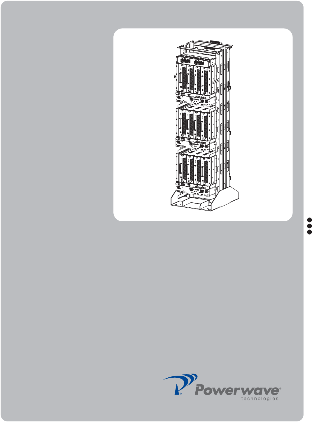
PAF-0813-E0-001
MCPA System
Installation and
Service Manual

© 2007 Powerwave Technologies Incorporated. All rights reserved.
Powerwave Technologies, and the Powerwave logo are registered trademarks.
This Powerwave product is intended only for installation in a RESTRICTED ACCESS LOCATION and is designed to
operate within the Normal Operating (typical operating) ranges or conditions specified in this document. Operation of
this equipment beyond the specified ranges in this document may cause:
1. Spurious emissions that violate regulatory requirements.
2. The equipment to be automatically removed from service when maximum thresholds are exceeded.
3. The equipment to not perform in accordance with its specifications.
It is the Operator's responsibility to ensure this equipment is properly installed and operated within Powerwave operat-
ing specifications to obtain proper performance from the equipment and to comply with regulatory requirements.
For PERMANENTLY CONNECTED EQUIPMENT, a readily accessible disconnect device shall be incorporated in the
building installation wiring.
PAF-0813-E0-001 Warnings, Cautions, and Notes
044-05287 Rev A i
Warnings, Cautions, and Notes
Warnings, Cautions, and Notes are found throughout this manual where applicable. The associated
icons are used to quickly identify a potential condition that could result in the consequences described
below if precautions are not taken. Notes clarify and provide additional information to assist the user.
WARNING: This warning symbol means danger. You are in a situation that could cause
bodily injury. Before you work on any equipment, be aware of the hazards involved with
electrical and RF circuitry and be familiar with standard practices for preventing accidents
CAUTION: This caution symbol means reader be careful. In this situation, the user might do
something that could result in equipment damage or loss of data.
NOTE This note symbol means reader take note. Notes contain helpful suggestions or references to
material not covered in the document. Procedures are not contained in notes.

Revision Record PAF-0813-E0-001
ii 044-05287 Rev A
Revision Record
Revision Letter Date of Change Reason for Change
A April 2007 Initial release

044-05287 Rev A i
Table of Contents
Chapter 1 - Product Description
Introduction ................................................................................................................................................... 1-1
Scope of Manual ........................................................................................................................................... 1-1
Product Description ....................................................................................................................................... 1-1
Functional And Physical Specifications ........................................................................................................ 1-1
Chapter 2 - Controls and Indicators
Introduction ................................................................................................................................................... 2-1
Subrack ......................................................................................................................................................... 2-1
Ethernet Connector Pinout ..................................................................................................................... 2-2
RS-485 Interface .................................................................................................................................... 2-3
Filter I/O (if used) .................................................................................................................................... 2-3
MCPA ............................................................................................................................................................ 2-3
Filter (if used) ................................................................................................................................................ 2-4
Circuit Breaker Panel .................................................................................................................................... 2-6
Chapter 3 - Installation
Introduction ................................................................................................................................................... 3-1
Site Survey .................................................................................................................................................... 3-1
Space Requirements .................................................................................................................................... 3-1
Unpacking and Inspection ............................................................................................................................. 3-1
Electrical Service Recommendations ........................................................................................................... 3-1
Cooling Requirements .................................................................................................................................. 3-2
Installation Instructions ................................................................................................................................. 3-2
PAF ......................................................................................................................................................... 3-2
Seismic Brace (Optional) ........................................................................................................................ 3-3
DC Connections ..................................................................................................................................... 3-3
RS-485 Alarm Interface .......................................................................................................................... 3-5
MCPA ..................................................................................................................................................... 3-5
Initial Start-Up and Power Setting Procedures ............................................................................................. 3-6
Initial Start Up ......................................................................................................................................... 3-6
Chapter 4 - Maintenance
Introduction ................................................................................................................................................... 4-1
Periodic Maintenance ................................................................................................................................... 4-1
Troubleshooting ............................................................................................................................................ 4-1
Clearing Alarm Faults ............................................................................................................................. 4-2
System Component Part Numbers ............................................................................................................... 4-2
Field Replacement Procedures ..................................................................................................................... 4-2
MCPA ..................................................................................................................................................... 4-3
Subrack Cooling Fans ............................................................................................................................ 4-4
Inside Mount .................................................................................................................................... 4-4
Rear Mount ...................................................................................................................................... 4-5
Fan Inside Mount to Rear Mount Conversion .................................................................................. 4-6
Subrack .................................................................................................................................................. 4-7
Filter ........................................................................................................................................................ 4-8
Circuit Breaker Panel .............................................................................................................................. 4-9
Return For Service Procedures .................................................................................................................. 4-10
Obtaining An RMA ................................................................................................................................ 4-10
Repackaging For Shipment .................................................................................................................. 4-10
Chapter 5 - Specifications
Introduction ................................................................................................................................................... 5-1

PAF-0813-E0-001 List of Tables
ii 044-05287 Rev A
List of Tables
2-1 Subrack Faceplate Interface Connectors, and Indicators........................................................................ 2-2
2-2 Ethernet Connector Pinout....................................................................................................................... 2-2
2-3 RS-485 Pinout.......................................................................................................................................... 2-3
2-4 MCPA Indicators and Controls................................................................................................................. 2-4
2-5 Filter Connector Descriptions................................................................................................................... 2-5
3-1 Sample of DC Cable Ratings................................................................................................................... 3-2
3-2 Thermal Loading...................................................................................................................................... 3-2
3-3 PAF Frame Installation Procedure...........................................................................................................3-3
3-4 DC Power Installation Procedure............................................................................................................. 3-4
3-5 RS-485 Alarm States ............................................................................................................................... 3-5
3-6 MCPA Installation Procedure................................................................................................................... 3-6
3-7 Initial Startup Procedure .......................................................................................................................... 3-6
4-1 Periodic Maintenance4-1
4-2 Troubleshooting ....................................................................................................................................... 4-2
4-3 System Components Part Number List.................................................................................................... 4-2
4-4 MCPA Removal and Replacement Procedure......................................................................................... 4-3
4-5 Inside Mount Cooling Fan Removal and Replacement Procedure.......................................................... 4-4
4-6 Rear Mount Cooling Fan Removal and Replacement Procedure............................................................ 4-5
4-7 Fan Conversion Procedure...................................................................................................................... 4-6
4-8 Subrack Removal and Replacement Procedure...................................................................................... 4-7
4-9 Filter Removal and Replacement Procedure........................................................................................... 4-8
4-10 Circuit Breaker Panel Removal and Replacement Procedure............................................................... 4-9

List of Figures PAF-0813-E0-001
044-05287 Rev A iii
List of Figures
1-1 System Block Diagram ............................................................................................................................ 1-2
1-2 PAF System Model.................................................................................................................................. 1-2
1-3 Subrack.................................................................................................................................................... 1-3
1-4 MCPA ...................................................................................................................................................... 1-3
1-5 Filter (if used)........................................................................................................................................... 1-3
1-6 Circuit Breaker Panel............................................................................................................................... 1-4
2-1 Subrack Interface Panel Connectors....................................................................................................... 2-1
2-2 Subrack Rear +27 VDC Connector Block................................................................................................ 2-1
2-3 MCPA Controls and Indicators ................................................................................................................ 2-3
2-4 Filter Front Connections .......................................................................................................................... 2-4
2-5 Filter Front Plate Indicators...................................................................................................................... 2-5
2-6 Circuit Breaker Panel Front and Top View .............................................................................................. 2-6
3-1 Frame Installation .................................................................................................................................... 3-3
3-2 Power Connections.................................................................................................................................. 3-4
3-3 Return Bus connection ............................................................................................................................ 3-4
3-4 Frame to Halo Ground Connection Example........................................................................................... 3-5
3-5 MCPA Front Panel Features.................................................................................................................... 3-6
4-1 MCPA Removal and Replacement .......................................................................................................... 4-3
4-2 Inside Mount Cooling Fan Removal and Replacement ........................................................................... 4-4
4-3 Rear Mount Cooling Fan Removal and Replacement ............................................................................. 4-5
4-4 Fan Inside Mount to Rear Mount Conversion .......................................................................................... 4-6
4-5 Subrack Removal and Replacement ....................................................................................................... 4-7
4-6 Filter Removal and Replacement ............................................................................................................ 4-8
4-7 Breaker Panel Unit Removal and Replace .............................................................................................. 4-9

PAF-0813-E0-001
044-05287 Rev A iv
This page intentionally left blank

044-05287 Rev A 1-1
Chapter 1
Product Description
Introduction
This manual contains information and procedures for installation, operation, and maintenance of the PAF-
0813-E0-001 Multi-Carrier Power Amplifier (MCPA) Indoor System. The manual is organized into chapters as
follows.
Scope of Manual
This manual is intended for use by service technicians familiar with similar types of equipment. It contains
service information required for the equipment described and is current as of the printing date. Changes which
occur after the printing date may be incorporated by a complete manual revision or alternatively as additions.
Product Description
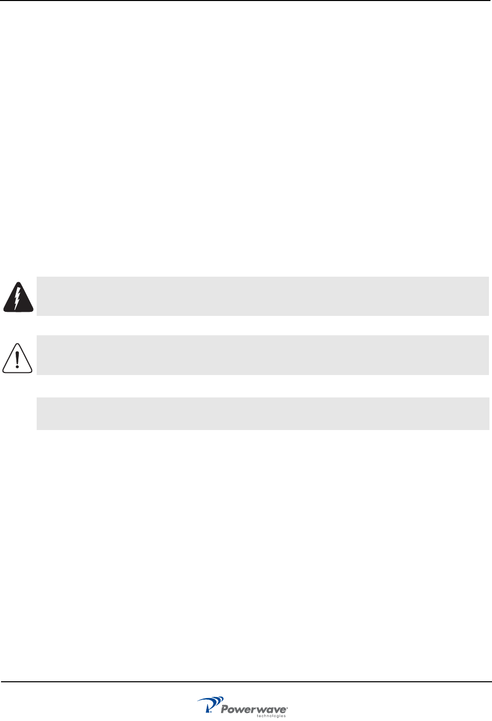
The PAF-0813-E0-001 system, shown in the Figure 1-1 block diagram, is an 850 MHz, 4-way combined,
frame-mounted BTS solution. The PAF system contains three MCPA subracks, each capable of containing up
to four MCPAs, three filters, and one DC circuit breaker panel.
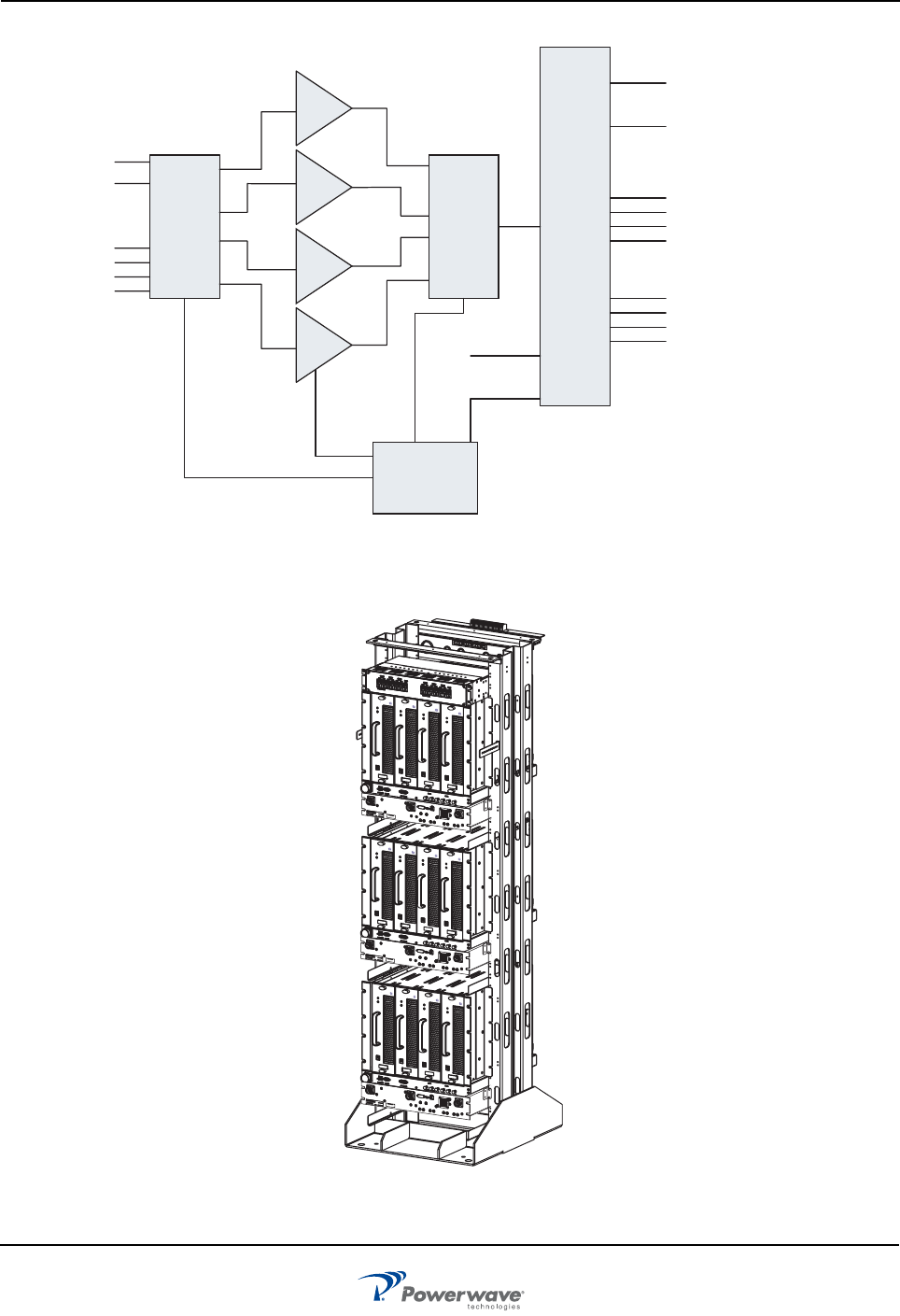
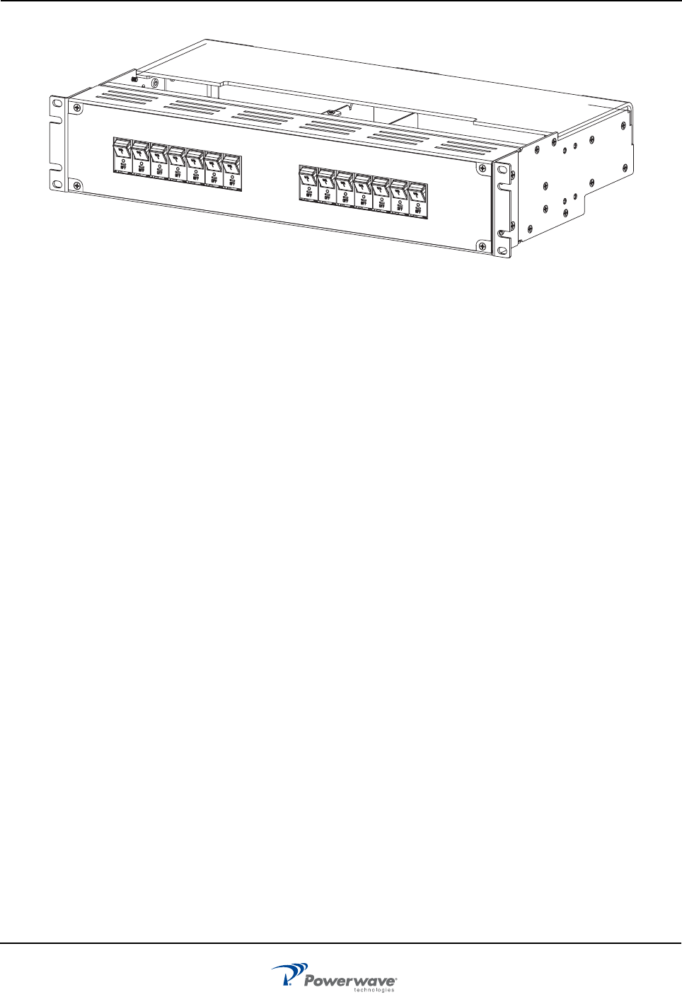
The MCPA subrack, shown in Figure 1-3, contains linear, feed-forward MCPAs that operate in the 869 - 894
MHz range. Each subrack is also equipped with automatic power control (APC), an ethernet connection, an
RS-485/RS-232 connection, a filter I/O port, and two cooling fans. The subrack is installed on sliding rails so
that it can be pulled forward to allow access to the rear of the subrack.
The MCPA, shown in Figure 1-4, is an 850 MHz module that produces a typical output of 160 watts (52.0
dBm) before system losses, with an instantaneous bandwidth of 25 MHz.
The filter assembly, shown in Figure 1-5, if used, supresses unwanted signals and non-linear components of
the signal from the amplifiers.
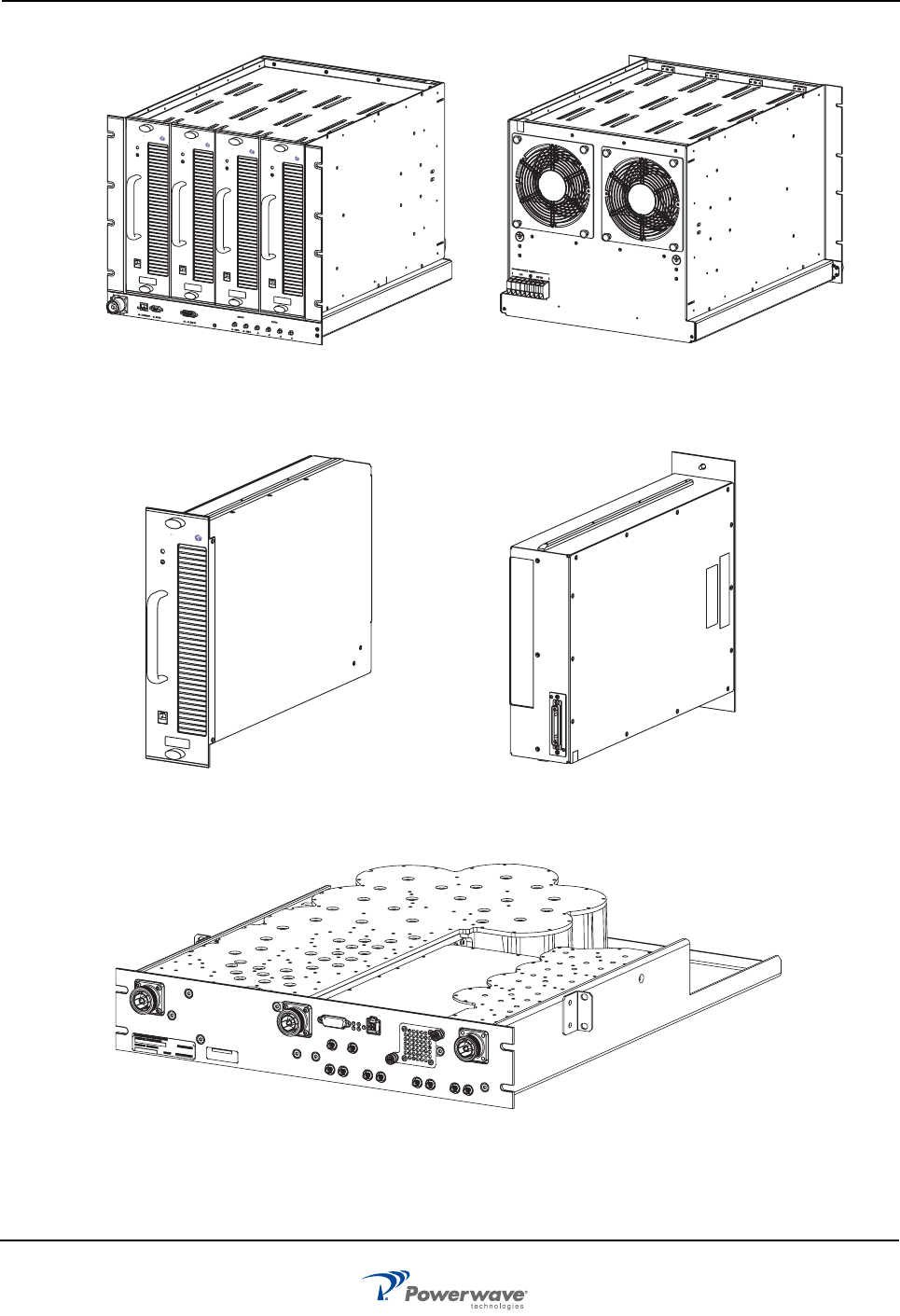
The circuit breaker panel, shown in Figure 1-8, consists of two +27 VDC input buses (A and B), and a system
circuit breaker panel. The panel receives +27 VDC from the BTS and then distributes circuit breaker protected
DC power to the individual subracks.
Functional And Physical Specifications
PAF-081X-P0-001 system functional and physical specifications are listed in Chapter 5.
❑Chapter 1 - Product Description
❑Chapter 2 - Controls and Indicators
❑Chapter 3 - Installation
❑Chapter 4 - Maintenance
❑Chapter 5 - Specifications
PAF-0813-E0-001 Functional And Physical Specifications
1-2 044-05287 Rev A
Figure 1-1 System Block Diagram
Figure 1-2 PAF System Model
Input
Combiner/
Splitter Combiner Filter
MCPA-0
MCPA-1
MCPA-2
MCPA-3
Analog
Input
Digital
Input
Main to/from Antenna
(T X / R X)
Diversity from Antenna
(RX)
Analog 1 (Main) to BTS
Analog 2 (Main) to BTS
Digital 1 (Main) to BTS
Digital (Main) to BTS
DC Power
Controller
2
Analog 1 (Diversity) to BTS
Analog
2
(Diversity) to BTS
Digital 1 (Diversity) to BTS
Digital (Diversity) to BTS
2
OFF
PC I/O
850 MHz
STATUS
RESET
ON
Alcatel Lucent
OFF
PC I/O
850 MHz
STATUS
RESET
ON
Alcatel Lucent
OFF
PC I/O
850 MHz
STATUS
RESET
ON
Alcatel Lucent
OFF
PC I/O
850 MHz
STATUS
RESET
ON
Alcatel Lucent
OFF
PC I/O
850 MHz
STATUS
RESET
ON
Alcatel Lucent
OFF
PC I/O
850 MHz
STATUS
RESET
ON
Alcatel Lucent
OFF
PC I/O
850 MHz
STATUS
RESET
ON
Alcatel Lucent
OFF
PC I/O
850 MHz
STATUS
RESET
ON
Alcatel Lucent
OFF
PC I/O
850 MHz
STATUS
RESET
ON
Alcatel Lucent
OFF
PC I/O
850 MHz
STATUS
RESET
ON
Alcatel Lucent
OFF
PC I/O
850 MHz
STATUS
RESET
ON
Alcatel Lucent
OFF
PC I/O
850 MHz
STATUS
RESET
ON
Alcatel Lucent
Functional And Physical Specifications PAF-0813-E0-001
044-05287 Rev A 1-3
Figure 1-3 Subrack
Figure 1-4 MCPA
Figure 1-5 Filter (if used)
Front Rear
OFF
PC I/O
850 MHz
STATUS
RESET
ON
AlcatelLucent
OFF
PC I/O
850 MHz
STATUS
RESET
ON
AlcatelLucent
OFF
PC I/O
850 MHz
STATUS
RESET
ON
Alcatel Lucent
OFF
PC I/O
850 MHz
STATUS
RESET
ON
AlcatelLucent
Rear
Front
STATUS
RESET
ON
OFF
PC I/O
Alcatel Lucent
850 MHz
PAF-0813-E0-001 Functional And Physical Specifications
1-4 044-05287 Rev A
Figure 1-6 Circuit Breaker Panel
044-05287 Rev A 2-1
Chapter 2
Controls and Indicators
Introduction
This chapter contains descriptions of the PAF-0813-E0-001 subrack, MCPA, filter, and circuit breaker panel
interface connections, controls and indicators.
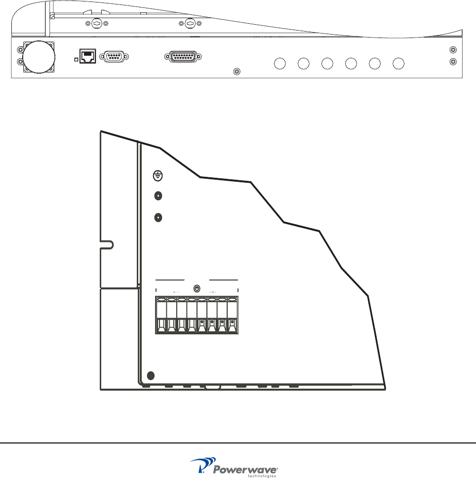
Subrack
The location of the subrack interface controls, connectors, and indicator are shown in Figures 2-1 and 2-2 and
feature descriptions are listed in Table 2-1.
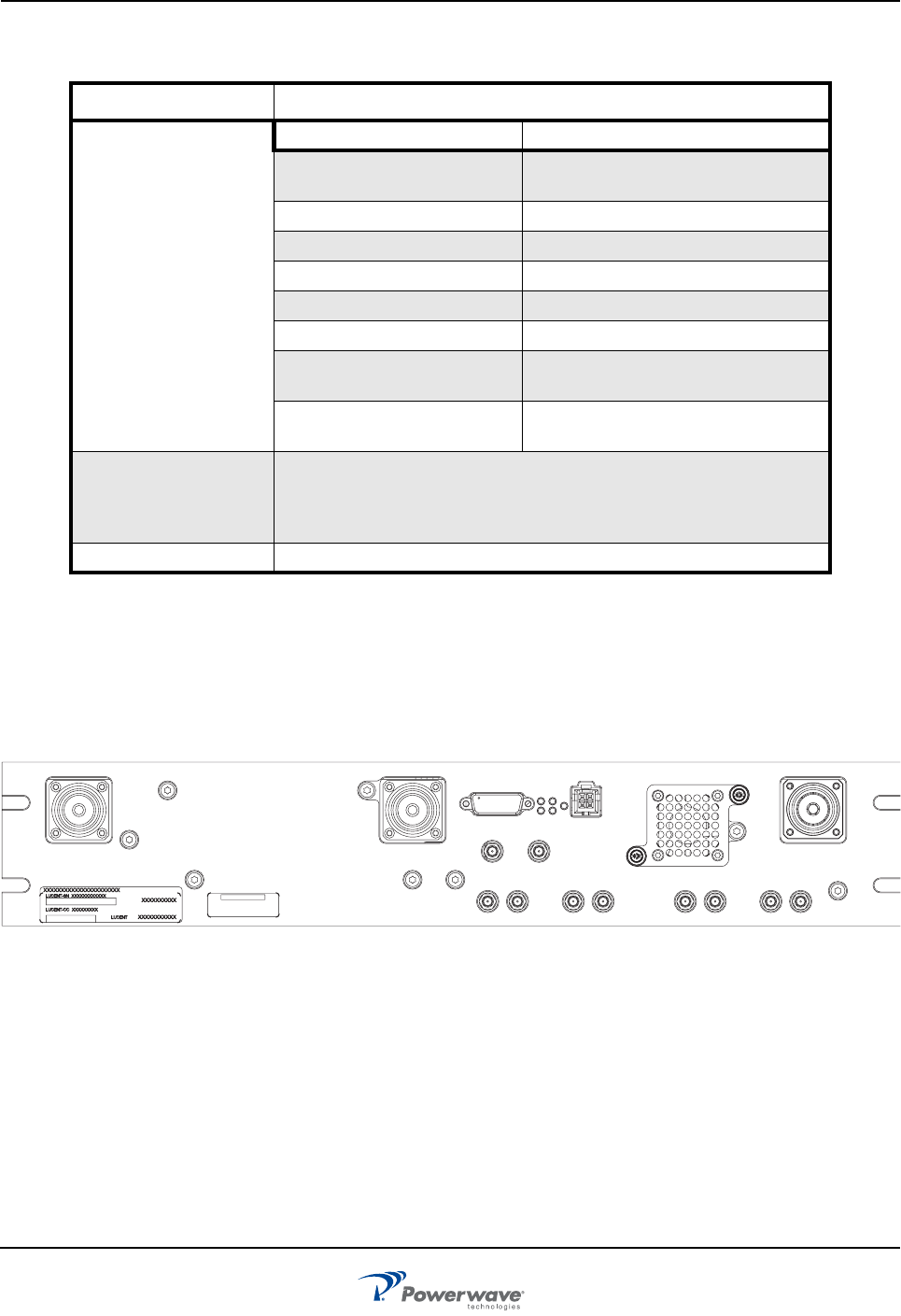
Figure 2-1 Subrack Interface Panel Connectors
Figure 2-2 Subrack Rear +27 VDC Connector Block
RF OUT ETHERNET RS485 FILTER I/O AMPS1 AMPS2 CDMA1 CDMA2 CDMA3 CDMA4
DIGITALANALOG
DC POWER
+27V
RETURN
01230123
Subrack PAF-0813-E0-001
2-2 044-05287 Rev A
Ethernet Connector Pinout
The Ethernet port is used for commuication with a personal computer (PC) or with a base station. The pin
layout for the Ethernet interface is listed in Table 2-2.
Table 2-1 Subrack Faceplate Interface Connectors, and Indicators
Connectors Description
RF
ANALOG (AMPS1,
AMPS2) Two SMA input connector
DIGITAL (CDMA1
through CDMA4) Four SMA input connectors
RF OUTPUT 7/16 DIN connector, composite transmit
signal output.
Status
ETHERNET RJ-45 connector used for host alarm
reporting, Pin layout is listed in Table 2-2
RS-232/RS-485 DB-9 connector used for host alarm
reporting. Pin Layout is listed in Table 2-3
Filter
Filter I/O DB-15 connector to provide control and
communication to filter (if used)
DC Power
+27 VDC Connector
Block (Rear of Subrack) Provide connections for +27 VDC circuit
breaker protected power from breaker panel
and frame ground bus return connections.
Table 2-2 Ethernet Connector Pinout
Pin Description
1Transmit Data (TX) +
2 Transmit Data (TX) -
3Receive Data (RX) +
4NC
5NC
6 Receive Data (RX) -
7NC
8NC
PAF-0813-E0-001 MCPA
044-05287 Rev A 2-3
RS-485 Interface
This RS-485 connector is used for serial communication and as an interface to the system for delivery of
alarms. Grounding pin 8 disables RS-485 communication. Table 2-3 lists the pin descriptions.
Filter I/O (if used)
This port is used for communication with the filter tray associated with the subrack.
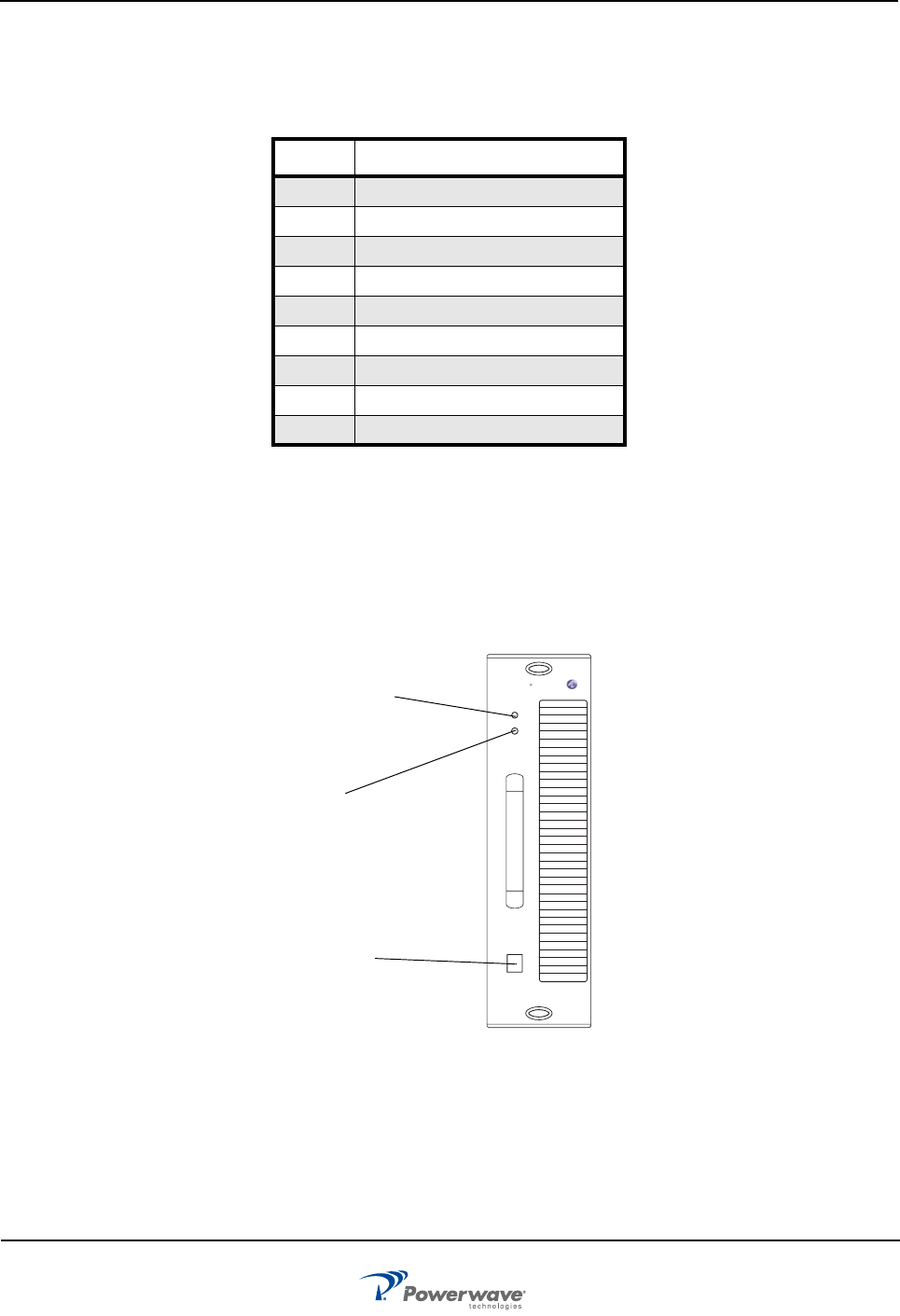
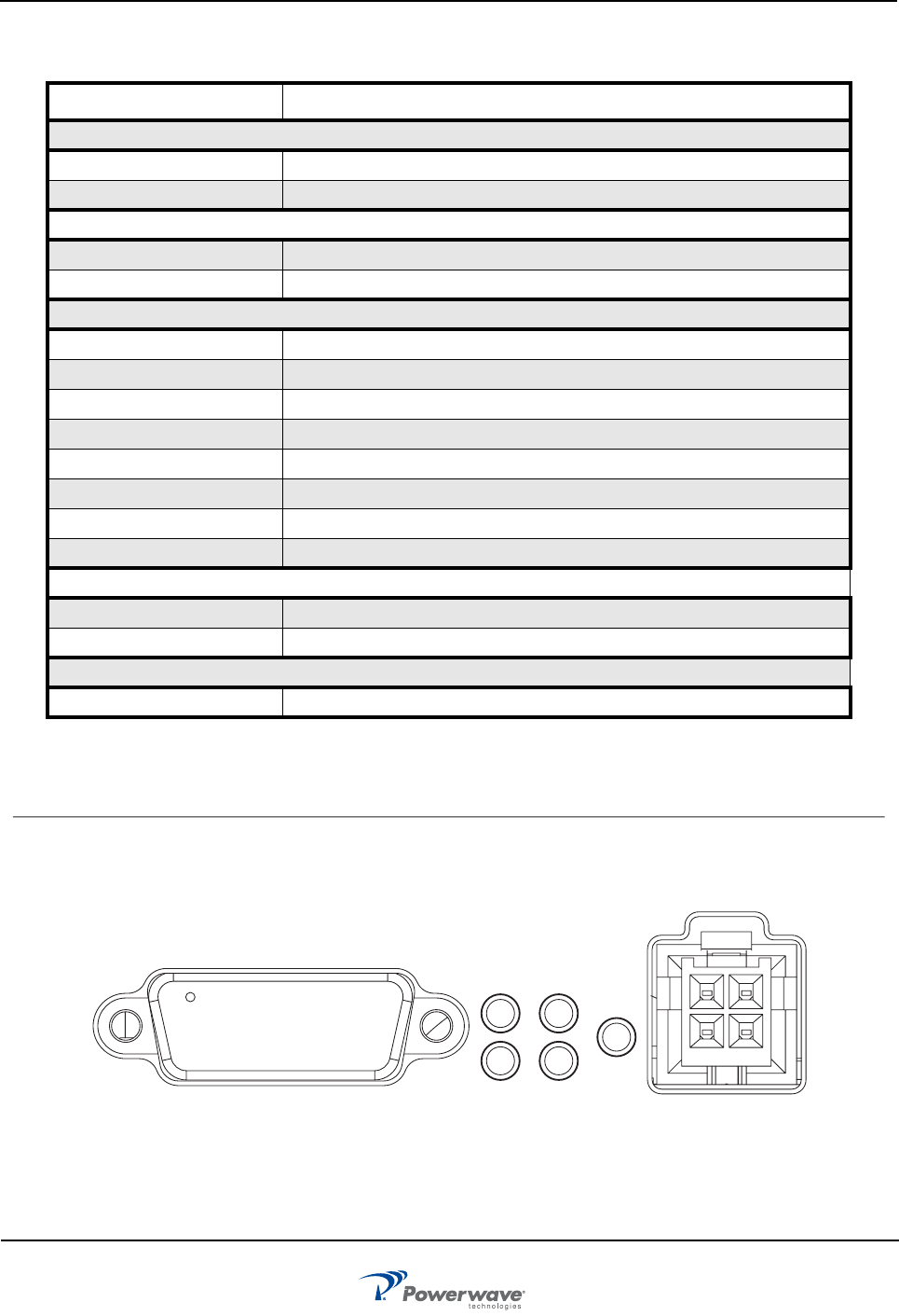
MCPA
The controls and indicators for the MCPA consist of an OFF/ON/RESET switch and tri-color LED status
indicator as shown in Figure 2-3 with detailed functions listed in Table 2-2.
Figure 2-3 MCPA Controls and Indicators
Table 2-3 RS-485 Pinout
Pin Description
1RS-485 RX+
2N/C
3 N/C
4 RS-485 RX-
5Ground
6 RS-485 TX-
7RS-485 TX+
8 Select = 1 (Not grounded)
9Ground
Multi-Color
Status LED
3-Position
Switch:
RESET
ON
OFF
RJ-11
Connector
Alcatel Lucent
STATUS
RESET
ONOFF
PC I/O
850 MH
z
Filter (if used) PAF-0813-E0-001
2-4 044-05287 Rev A
Filter (if used)
Figure 2-4 shows the front plate of the filter. Table 2-3 lists the descriptions of the connectors. Figure 2-5
shows the five indicators on the filter front panel. The LED will display a green light during normal operation
and red light if the indicated stage has suffered a catastrophic failure.
Figure 2-4 Filter Front Connections
Table 2-4 MCPA Indicators and Controls
Control/Indicator Description
STATUS (Multi-colored
LED Indicator)
LED Color MCPA Status.
Green (solid) RF enabled, OFF/ON/RESET switch
set to ON (middle position).
Green (blinking) Standby.
Yellow (solid) Major Alarm
Yellow (blinking) APC Activated
Red (solid) Critical Alarm, MCPA disabled.
Red (blinking) Over Temperature Alarm
Red/Yellow (blinking together) High Reverse Output Power 1 minute
validation period
Red/Yellow (alternating) Critical Alarm during remote firmware
download or checksum failure
Toggle Switch positions:
RESET (Up)
ON (Middle)
OFF (Down)
Resets MCPA. LED indicates boot mode, then turns solid green.
Enables MCPA. LED indicates solid green.
Disables MCPA. LED Indicates solid red.
RJ-11 RS-232 PC Interface for factory use only.
Antenna Main Antenna Diversity
MCPA RF Out DC Power
CDMA 1
Main Antenna Receive LNA Output Ports
CDMA 1
Diversity Antenna Receive LNA output port
Forward Main Power Coupler Port
RF Test Port
CDMA 2 AMPS 1AMPS 2 CDMA 2 AMPS 1AMPS 2
IIC
PAF-0813-E0-001 Filter (if used)
044-05287 Rev A 2-5
Figure 2-5 Filter Front Plate Indicators
Table 2-5 Filter Connector Descriptions
Connector/Cable Description
Antenna Connections
Antenna Main 7/16 connector - Dx0 (bi-directional) antenna port
Antenna Diversity 7/16 connector - Dx1 (simplex RX) antenna port
Subrack Connection
MCPA RF Out 7/16 connector - connects subrack to receive output signal
IIC DB-15 connector for communication between filter and subrack
BTS Connections
CDMA 1 Dx0 Receive LNA Output Port CDMA
CDMA 2 Dx0 Receive LNA Output Port CDMA
AMPS 1 Dx0 Receive LNA Input Port AMPS
AMPS 2 Dx0 Receive LNA Output Port AMPS
CDMA 1 Dx1 Receive LNA Output Port CDMA
CDMA 2 Dx1 Recevie LNA Output Port CDMA
AMPS 1 Dx1 Receive LNA Output Port AMPS
AMPS 2 Dx1 Receive LNA Output Port AMPS
Test Port Connections
RF Test Port SMA connector - Switched Coupler Port (4-way)
Forward Main Coupler Port SMA connector - Dx0 Forward Power Coupler Port
Power Connection
Power Power connection
DC Power
IIC
LNA
DX1DX0
RF
ON
TTLNA
Circuit Breaker Panel PAF-0813-E0-001
2-6 044-05287 Rev A
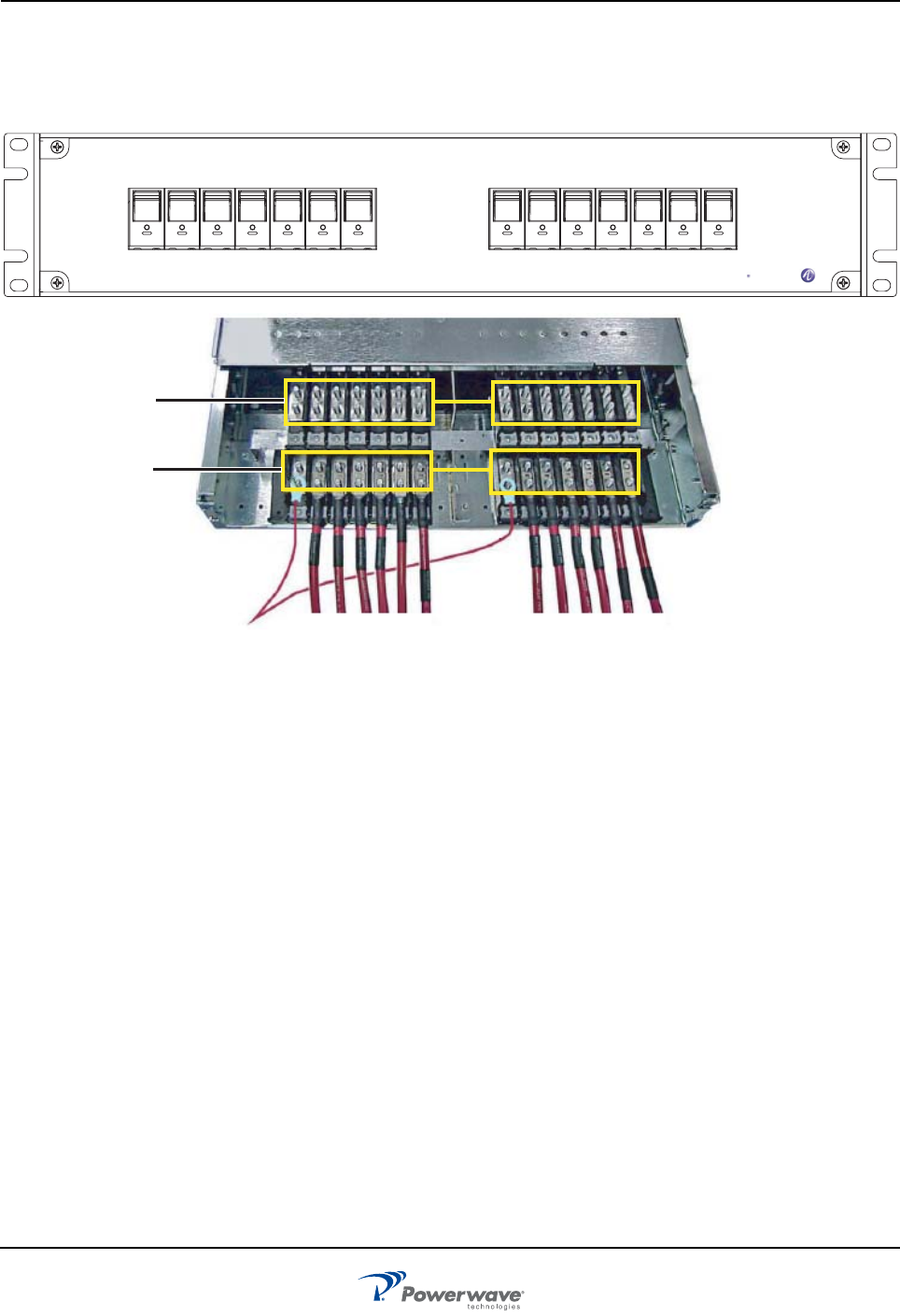
Circuit Breaker Panel
Figure 2-5 shows the switches on the front of the breaker panel and the cable connections on the rear.
Chapter 3 discusses power cable connection.
Figure 2-6 Circuit Breaker Panel Front and Top View
OFF OFF OFF OFF OFF OFF OFF OFF OFF OFF OFF OFF OFF OFF
ON
I
ON
I
ON
I
ON
I
ON
I
ON
I
ON
I
ON
I
ON
I
ON
I
ON
I
ON
I
ON
I
ON
I
AMP 0 AMP 2 AMP 0 AMP 2 AMP 0 AMP 2 AMP 1 AMP 3 AMP 1 AMP 3 AMP 1 AMP 3DIV 0 DIV 1
LOWEST SUBRACK LOWEST SUBRACK
SECTOR 0 SECTOR 1 SECTOR 2
ALPHA BETA GAMMA SECTOR 0 SECTOR 1 SECTOR 2
ALPHA BETA GAMMA
FILTERS FILTERS
Alcatel Lucent
Top

044-05287 Rev A 3-1
Chapter 3
Installation
Introduction
This chapter contains unpacking, inspection, installation instructions, and recommendations for installing the
PAF-0813-E0-001 MCPA Indoor System.
Site Survey
Powerwave recommends that a site survey be performed prior to equipment ordering or installation.
Performing a detailed site survey reduces or eliminates installation and turn-up delays. Pay particular
attention to AC or DC power availability, cooling needs, floor space, and RF/DC cabling/breaker requirements.
See Chapter 5 for system dimensions and weights.
Space Requirements
The PAF system requires the following floor space for clearance (W x D x H): 28.5 inches (724 mm) x 78.2
inches (1986 mm) x 38.5 inches (978 mm). To properly service the system, an additional 48 inches (1220 mm)
is required in the front of the unit. To permit proper airflow, allow a minimum of 8.27 inches (210 mm) behind
the PAF.
Unpacking and Inspection
This equipment has been operated, tested and calibrated at the factory. Carefully open the containers and
remove the equipment. Retain all packing material that can be reassembled in the event that the unit must be
returned to the factory. Please perform the following steps:
❑Visually inspect equipment for damage that may have occurred during shipment. If possible, in
the presence of the delivery person.
❑Check for evidence of water damage, bent or warped chassis, loose screws or nuts, or extrane-
ous packing material in connectors.
If the equipment is damaged, file a claim with the carrier once the extent of any damage is assessed.
If the equipment must be returned to the factory, contact the factory for a Return Material Authorization (RMA)
as described in Chapter 4.
Electrical Service Recommendations
Proper AC line conditioning and surge suppression is necessary on the primary AC input to the +27 VDC
power source. Powerwave recommends that all electrical service be installed in accordance with the National
Electrical Code (NEC) and any applicable state or local codes.
Table 3-1 lists a sample of DC cable ratings.
Cooling Requirements PAF-0813-E0-001
3-2 044-05287 Rev A
Cooling Requirements
Each MCPA at full power generates the BTUs per hour listed in Table 3-3. A 1-ton air conditioner offsets
12,000 BTUs of heat. The MCPA operates within the temperature environment specified in Chapter 5.
Fan speed is dependent on MCPA operating temperature. The fans remain off until the MCPAs exceed +43°C
base plate temperature. Once enabled, the fan remains on until all MCPA base plate temperatures are below
+41°C.
Installation Instructions
Install the PAF frame, DC and RF connections, alarms, and MCPAs as described in the following paragraphs.
PAF
To install the PAF frame, perform the instructions in Table 3-4.
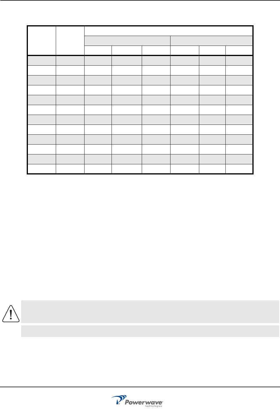
Table 3-1 Sample of DC Cable Ratings
AWG
or
MCM mm2
Copper
3 Conductor In Raceway Single Conductor In Free Air
75°C 90°C 110°C 75°C90°C110°C
10 540 45 50 55 65
8 8 57 55 60 70 75 85
613 76 70 80 95 100 120
4 21 101 95 105 125 135 160
234 135 125 135 170 185 210
1 42 158 145 160 195 215 245
053 183 165 190 230 250 285
00 67 212 195 265 300
000 85 245 225 310 350
0000 107 287 260 360 405
MCM250 127 320 290 405 455
MCM300 152 359 320 445 505
Based on ambient temperature of 30×C (86×F)100% Load Factor
Source: Industrial Electric Wire & Cable Inc., Technical Guide Vol. 4M 11/99, Table III Suggested
Ampacities - All Types of Insulations; Based on National Electric Code
CAUTION: The PAF frame, as factory shipped, weighs approximately 250 lbs (113 kg) to 428
lbs (194 kg) depending on configuration (MCPAs not included).
NOTE Reuse shipping pallet washers to secure PAF to installation site floor.
PAF-0813-E0-001 Installation Instructions
044-05287 Rev A 3-3
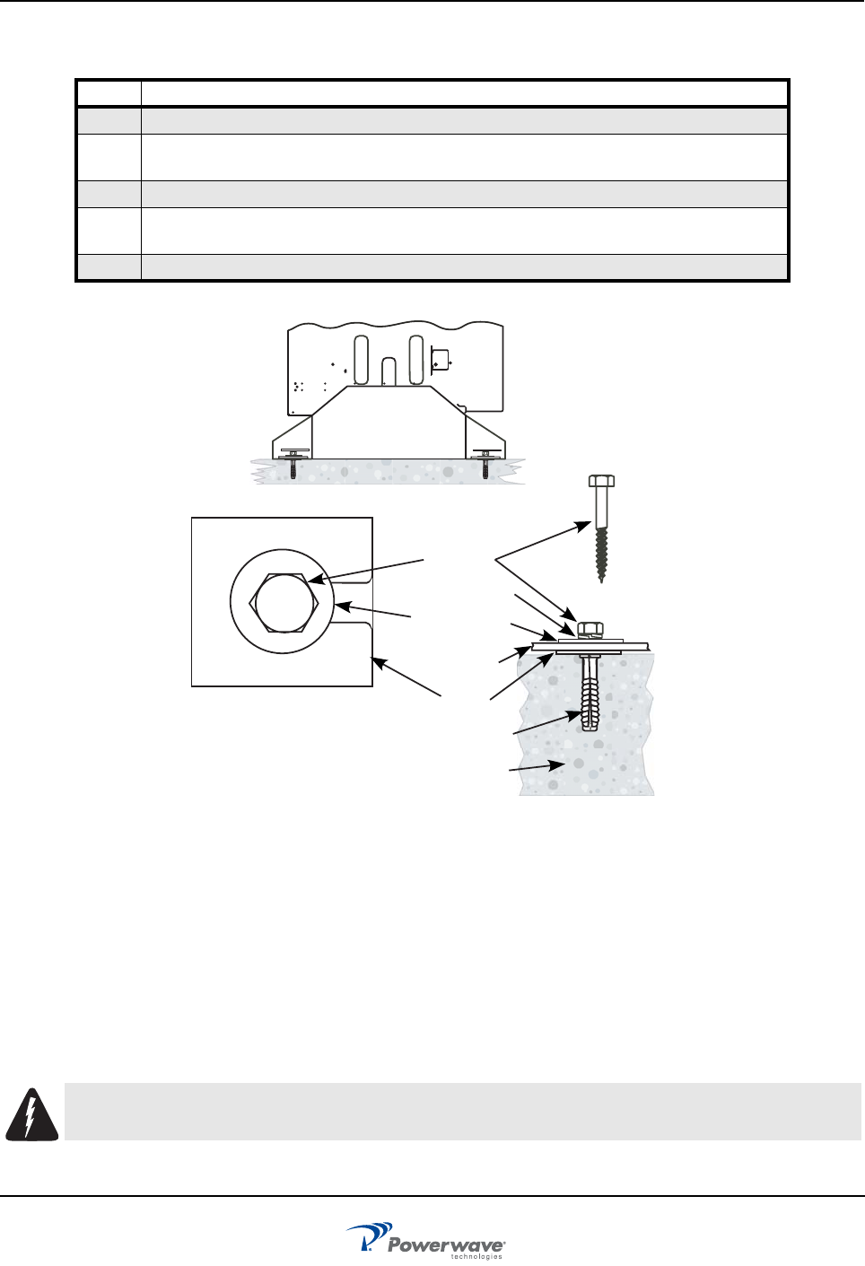
Figure 3-1 Frame Installation
Seismic Brace (Optional)
The PAF system meets GR-63-CORE, Section 4.4.1, Zone 4 compliance. If additional bracing is required,
Powerwave offers an optional seismic brace kit for those circumstances. Please contact a Powerwave sales
representative for additional information and assistance.
DC Connections
Connect and verify DC power cables between the BTS power plant and the PAF system circuit breaker panel
and PAF return bus located at the top of the PAF as instructed in Table 3-5. Required power is +27 VBC, and
each power input is directly connected through the circuit breaker in the front of the panel to the power output
directly below it in the panel.i
Table 3-2 PAF Frame Installation Procedure
Step Action
1. Set PAF frame in planned location
2. Mark floor drill holes on floor where lag bolts will be installed. Move frame to side. Refer
to lag bolt manufacturer’s instructions for hole depth and diameter
3. Move frame back over drilled holes
4. Use a level to ensure frame is not leaning. Insert shims between frame base and floor to
level frame. Shims should wrap around lag bolts as shown in Figure 3-2
5. Secure frame in place with red eye lag bolts and appropriate washers
WARNING: Turn off external DC power before connecting DC power cables.
Concrete
Lag Anchor
Shim
Cabinet
Flat Washer
Lock Washer
Lag Bolt
Installation Instructions PAF-0813-E0-001
3-4 044-05287 Rev A
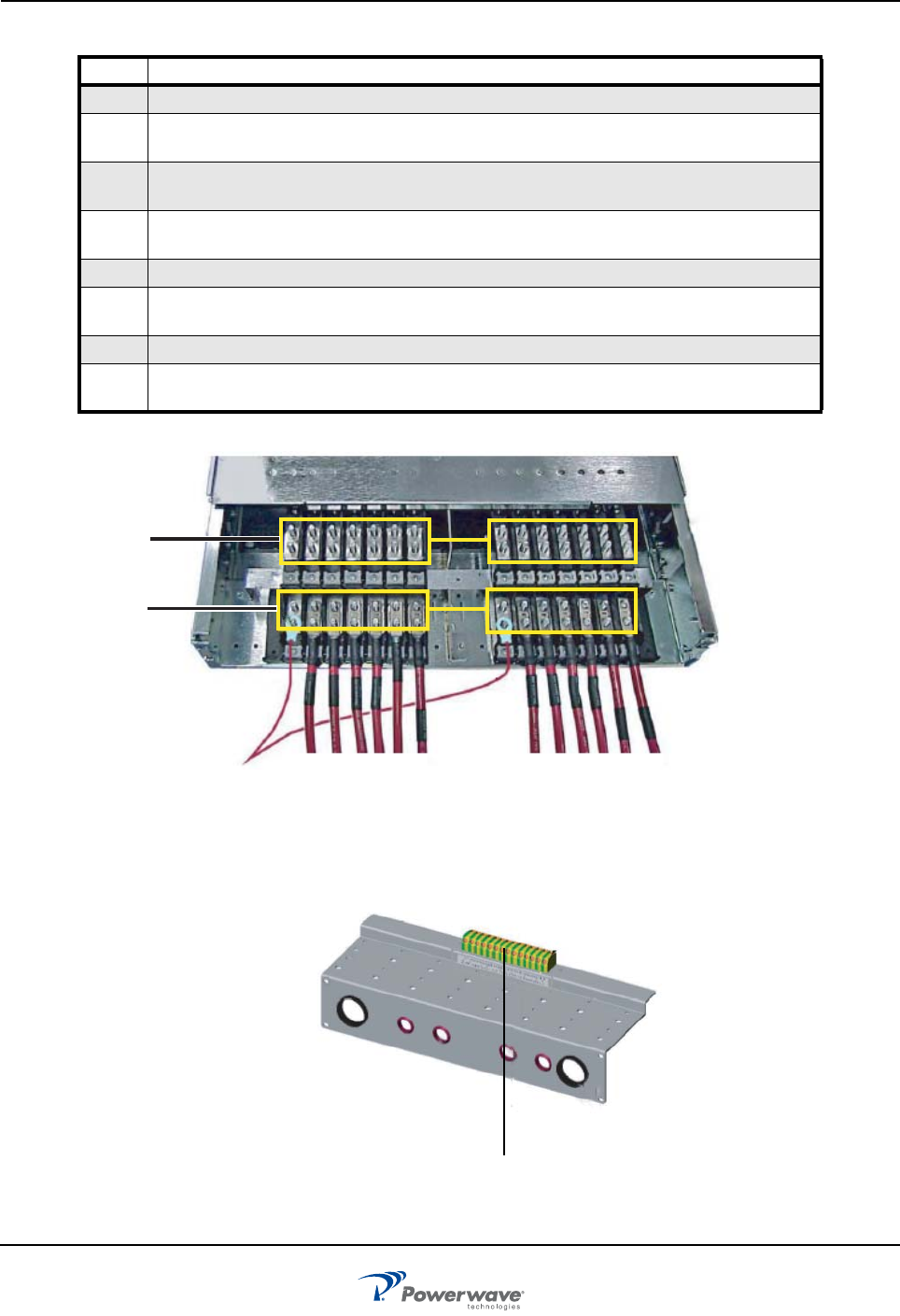
Figure 3-2 Power Connections
Figure 3-3 Return Bus connection
Table 3-3 DC Power Installation Procedure
Step Action
1. Remove circuit breaker panel top protective cover
2. Connect fourteen individual red power cables, one to each input on the upper row of
connections. (designated Row A Figure 3-2)
3. Attach opposite ends of red MCM 250 powr cables to power plant’s main DC bus bar
after main shunt.
4. Insert fourteen individual black power cables into front of yellow and green ground
connections as shown in Figure 3-3 and tighten screws
5. Attach opposite ends of black power cables to power plant's main DC return bus bar
6. Connect PAF frame to halo grounding system at frame top (four locations) using green 6
AWG cable as shown in Figure 3-4
7. Reinstall circuit breaker panel top protective cover.
8. Affix supplied ground sticker directly beneath one utilized frame grounding points shown
in Figure 3-4
Row A
Row B
Ground Return Connections