Powerwave Technologies 5JS0097 RF Power Amplifier Frame User Manual 044 05287 PAF 0813 E0 001
Powerwave Technologies Inc RF Power Amplifier Frame 044 05287 PAF 0813 E0 001
Contents
- 1. Users Manual Part 1
- 2. Users Manual Part 2
Users Manual Part 2
PAF-0813-E0-001 Installation Instructions
044-05287 Rev A 3-5
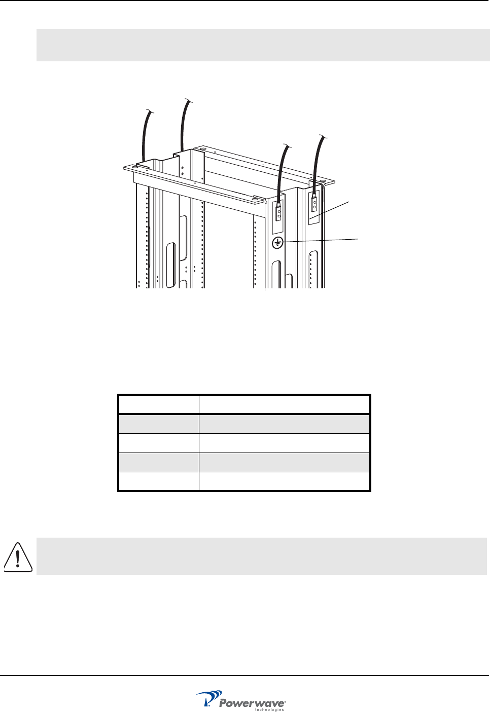
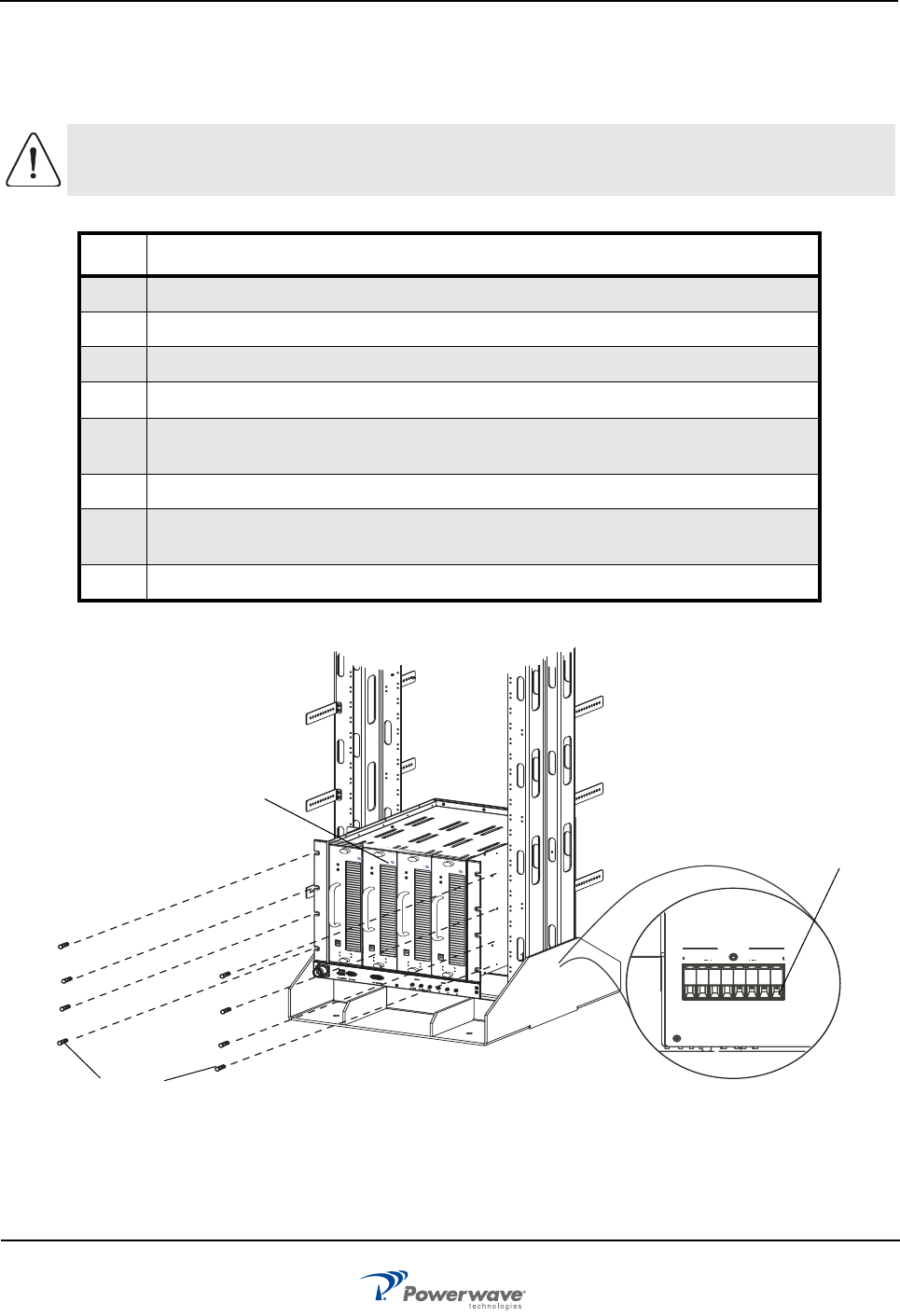
Figure 3-4 Frame to Halo Ground Connection Example
RS-485 Alarm Interface
The RS-485 alarm interface provides the BTS controller with system status via a 1 byte protocol. The baud
rate is fixed at 15.6 K. Table 3-6 lists the available alarm states..
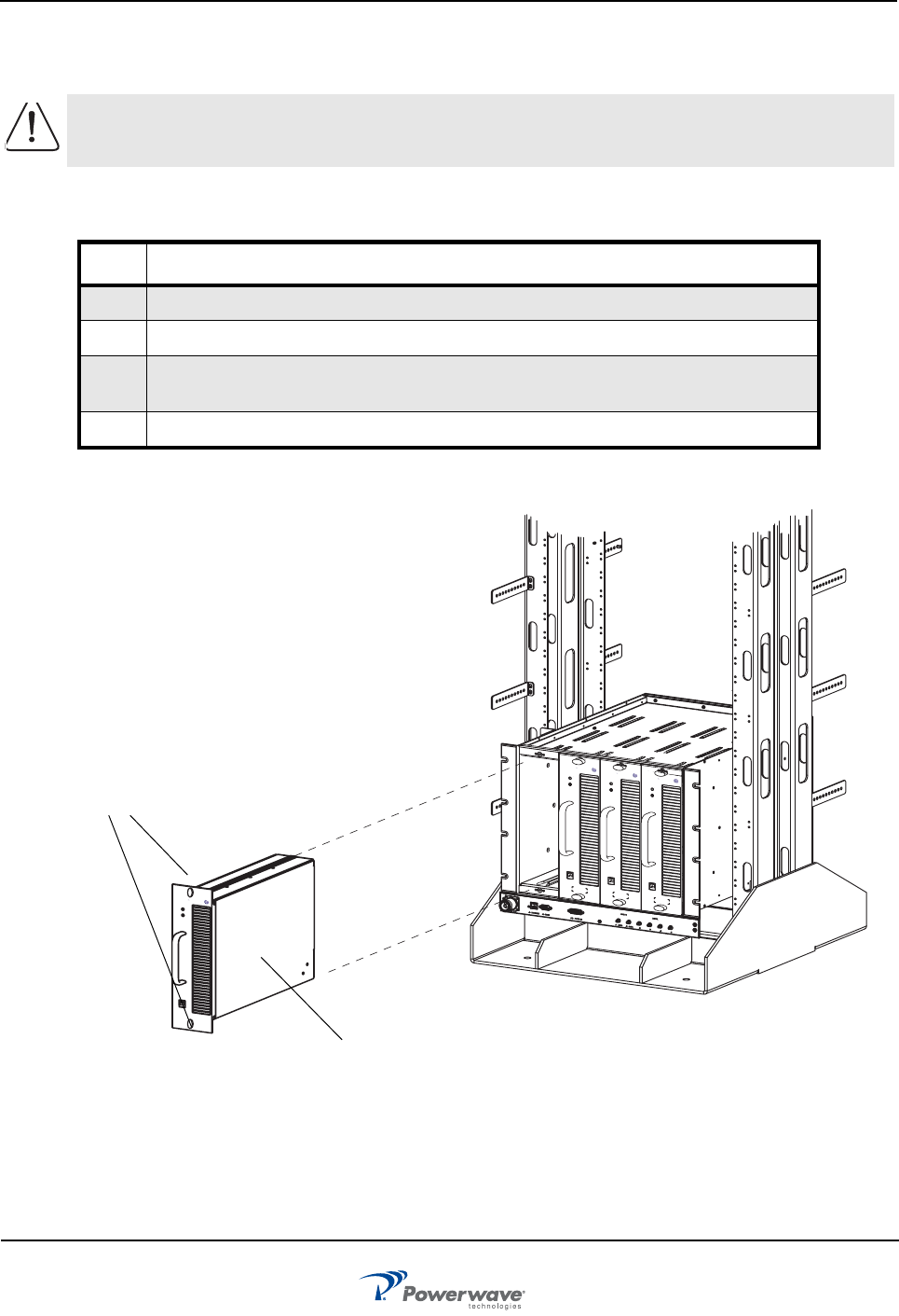
MCPA
Install the MCPAs as instructed in Table 3-7.
NOTE DO NOT remove metallic tape at frame top when connecting to Halo ground system. Removing tape
voids PAF frame warranty.
Table 3-4 RS-485 Alarm States
AlarmState Definition
No Alarm
Minor Alarm Any or all fans fail
Major Alarm Any one MCPA module disabled
Critical All MCPA modules disabled
CAUTION: REPLACE THIS SECTION WITH UPDATE Slamming or forcing the MCPA into the
subrack may cause the pins on the 21-pin D-Sub connector to become recessed or broken.
Ground
Sticker
To Halo
Ground
To Halo
Ground
Metallic
Tape
Initial Start-Up and Power Setting Procedures PAF-0813-E0-001
3-6 044-05287 Rev A
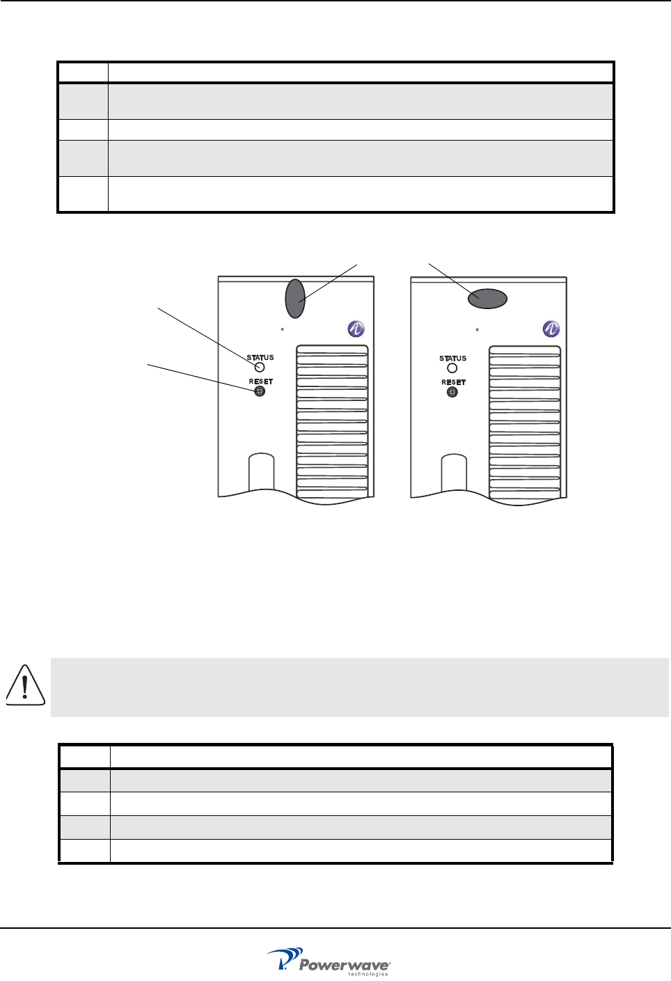
Figure 3-5 MCPA Front Panel Features
Initial Start-Up and Power Setting Procedures
The following paragraphs provide initial startup, and power setting procedures.
Initial Start Up
To complete initial startup, perform the instructions listed in Table 3-8.
Table 3-5 MCPA Installation Procedure
Step Action
1. Inspect MCPA 21-pin connector. Verify all pins are straight, no pins are recessed, and
alignment shield is not bent
2. Set MCPA power OFF/ON/RESET switch to OFF
3. Rotate MCPA quarter-turn fasteners counter-clockwise to unlock position shown in
Figure 3-8
4. Install MCPA(s) into subrack. To secure each MCPA, rotate quarter-turn fasteners
clockwise to lock position as shown in Figure 3-8
CAUTION: Excessive input power may damage MCPA. Before applying power, ensure MCPA
inputs and outputs are properly terminated at 50 ohms. Do not operate MCPA without a load
attached. Refer to Chapter 5 for input power requirements.
Table 3-6 Initial Startup Procedure
Step Action
1. Verify all input and output cables are properly connected
2. Turn on +27 VDC supply to MCPA
3. Set all MCPA front panel OFF/ON/RESET switches to ON (middle) position
4. Allow MCPAs to warm up for at least two minutes before taking power readings
Unlocked Locked
LED Status
Indicator
RF Switch:
RESET
ON
OFF
Quarter-Turn
Fasteners
ON
OFF
ON
OFF
Alcatel Lucent Alcatel Lucent
044-05287 Rev A 4-1
Chapter 4
Maintenance
Introduction
This chapter contains periodic maintenance and performance test procedures for the PAF-081X-P0-001 Multi-
Carrier Power Amplifier (MCPA) system.
Periodic Maintenance
Periodic maintenance requirements are listed in Table 4-1, as well as the intervals at which the tasks should
be performed.
Troubleshooting
The following paragraphs contain a list of problems that could occur and a few suggested actions that can
correct the problem. If the suggested corrective action does not eliminate the problem, please contact your
Powerwave field representative or the factory for further instructions.
NOTE Do not break seals on equipment under warranty or warranty will be null and void. Do not return
equipment for warranty or repair service until factory shipping instructions are received.
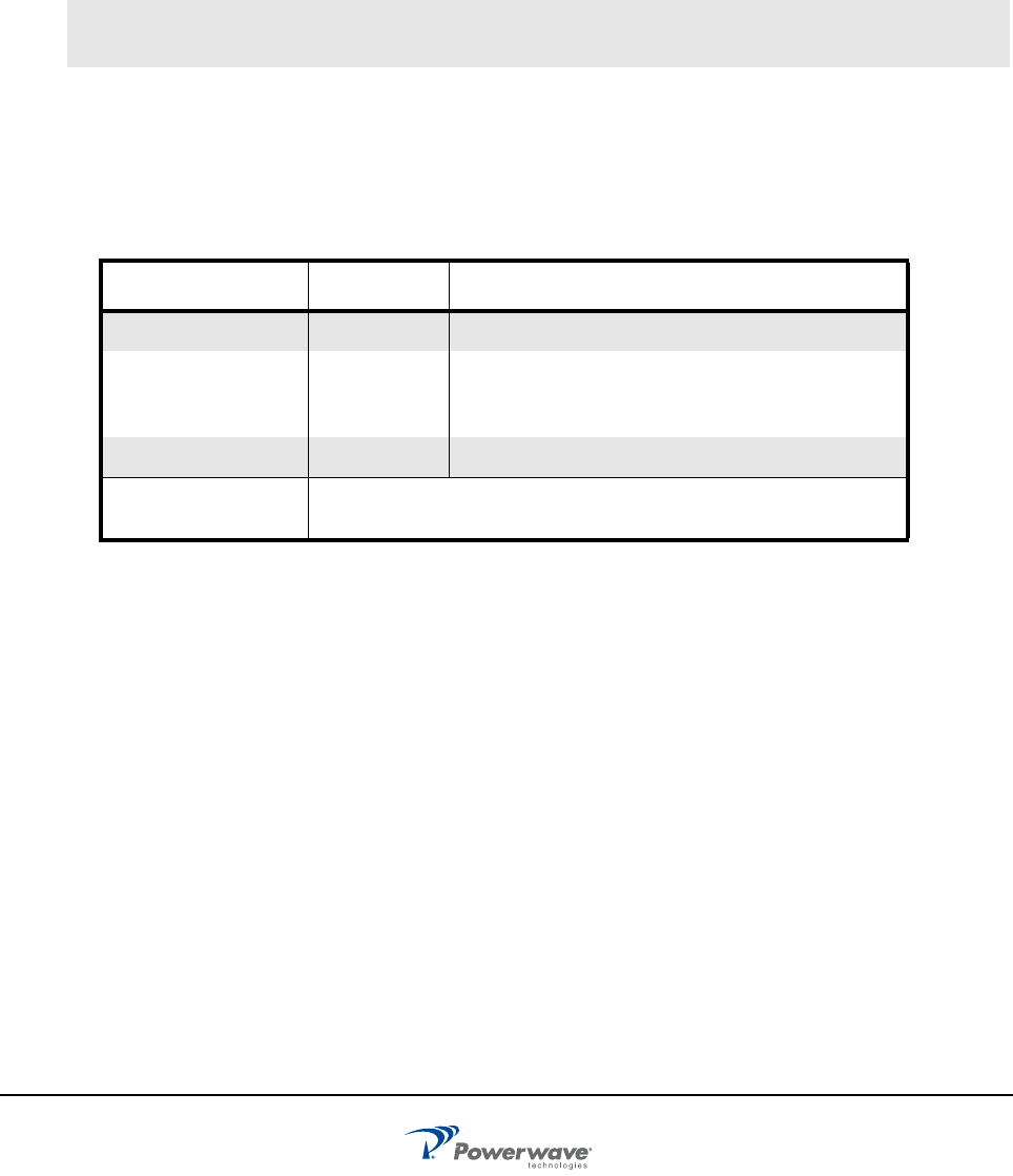
Table 4-1 Periodic Maintenance
Task Interval Action
Inspection:
Cables and Connec-
tors 12 Months Inspect signal and power cables for frayed
insulation. Check RF connectors to be sure that
they are tight
Optional Antenna VSWR sweep
Cleaning: Fans and
Equipment Clean as required depending on equipment operating environment
System Component Part Numbers PAF-0813-E0-001
4-2 044-05287 Rev A
Clearing Alarm Faults
Setting the MCPA front panel OFF/ON/RESET switch to RESET can clear many alarm faults. An attempt to
reset the MCPA should be your first course of action. 24-Hour technical support service is available at our
main phone number 888-797-9283 or 714-466-1000; select the "System Operator Technical Support" option
to receive assistance from Powerwave's Applications Support Group. Refer to Table 4-2 for troubleshooting
suggestions.
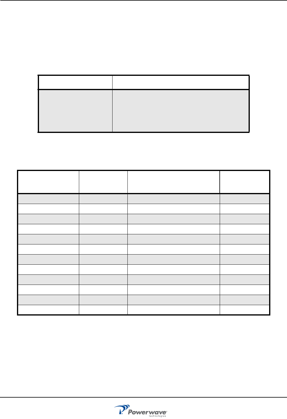
System Component Part Numbers
Table 4-3 lists the model/part numbers for ordering individual system components and manuals.
Field Replacement Procedures
The following parts and modules can be replaced in the field on site by a qualified technician with experience
maintaining RF power amplifiers and similar equipment:
Table 4-2 Troubleshooting
Problem Suggested Action
MCPA Inoperative (MCPA
front panel LED red) 1. Set MCPA OFF/ON/RESET toggle switch
momentarily to RESET
2. Check for proper power supply voltage
3. Verify all RF connections
4. Contact your field representative or factory
Table 4-3 System Components Part Number List
Model/Part Number Manual Number Description
System
Maximum
Quantity
G3L-830-160 -160 Watt, 850 MHz MCPA 12
800-09666-001 - Subrack Fan Assembly 2 per subrack
MCR40830-1-4 -Subrack, 4-way combined 3
800-07829-002 - Panel, blank, MCPA as required
FIL-0830A -Filter, 850 MHz, A-band 3
FIL-0830B - Filter, 850 MHz, B-band 3
800-11185-600 -Panel, Circuit Breaker 1
1002530 - Circuit Breaker, 50 A 12
1002529 -Circuit Breaker, 15 A 2
700-18766-001 - Cable, RF, 7/16 DIN-R-MA 3
700-18767-001 -Cable, Filter, DB-15 to DB-15 3
700-18133-100 - Cable, Filter, DC 1
❑MCPA ❑Fiter
❑Cooling Fans ❑Circuit Breaker Panel
❑Subrack
PAF-0813-E0-001 Field Replacement Procedures
044-05287 Rev A 4-3
MCPA
To replace an MCPA module, shown in Figure 4-1, perform the steps in Table 4-3.
Figure 4-1 MCPA Removal and Replacement
CAUTION: To prevent damage to MCPA rear connector, support rear of MCPA when
removing from subrack. The MCPA weight is approximately 20 lbs (9.1 kg).
Table 4-4 MCPA Removal and Replacement Procedure
Step Action
1. Set MCPA front panel OFF/ON/RESET switch to OFF
2. Rotate MCPA module quarter-turn fasteners counterclockwise
3. With steady even pressure, use handle on front of MCPA to pull module out of enclosure
as shown in Figure 4-1
4. Replace MCPA module in reverse order of removal
STATUS
RESET
STATUS
RESET
STATUS
RESET
PC I/O PC I/O
PC I/O
STATUS
RESET
PC I/O
ON
OFF
AlcatelLucent
AlcatelLucent AlcatelLucent AlcatelLucent
MCPA
Quarter-Turn
Fasteners
Field Replacement Procedures PAF-0813-E0-001
4-4 044-05287 Rev A
Subrack Cooling Fans
Refer to Chapter 3 - Air Conditioning for cooling-fan operating parameters before replacing fans. To replace
an inside or rear mounted cooling fan or change the fan mounting configuration, proceed as follows:
Inside Mount
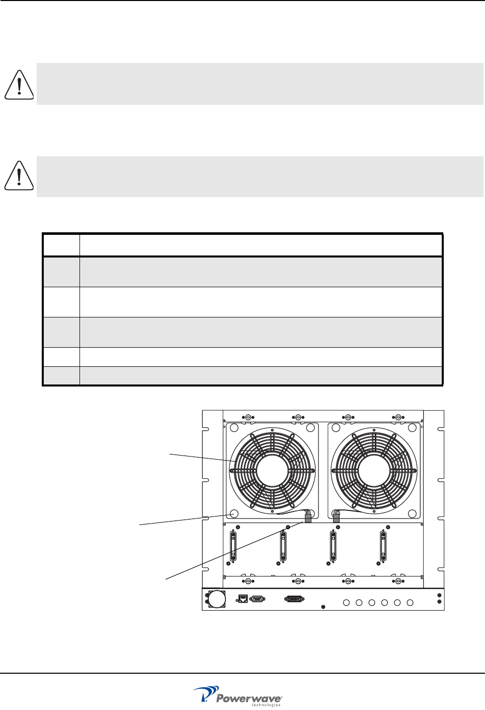
To replace the inside mounted fan, shown in Figure 4-2, perform the steps in Table 4-4.
Figure 4-2 Inside Mount Cooling Fan Removal and Replacement
CAUTION: To prevent damage to MCPA rear connector, support rear of MCPA when
removing from subrack. MCPA weight is approximately 20 lbs (9.1 kg).
CAUTION: The replacement fan may operate when the power connector is connected.
Ensure that no objects (fingers, screwdrivers, etc.) intrude into the fan area.
Table 4-5 Inside Mount Cooling Fan Removal and Replacement Procedure
Step Action
1. For fan assembly located behind blank panels, rotate quarter-turn fasteners on each
panel counter-clockwise to remove panels from subrack, then proceed to Step 4
2. For fan assembly located behind MCPAs, set each front panel OFF/ON/RESET switch
to OFF
3. Read above Caution. Rotate quarter-turn fasteners on each MCPA counter-clockwise
and remove MCPAs from subrack
4. Disconnect fan power connector and pull out snap fasteners to remove fan
5. Install replacement fan assembly in reverse order of removal
Cooling
Fan
Snap
Fasteners (4)
Power/Sense
Connector
Assembly
RF OUT ETHERNET RS485 FILTER I/O AMPS1 AMPS2 CDMA1 CDMA2 CDMA3 CDMA4
DIGITALANALOG
PAF-0813-E0-001 Field Replacement Procedures
044-05287 Rev A 4-5
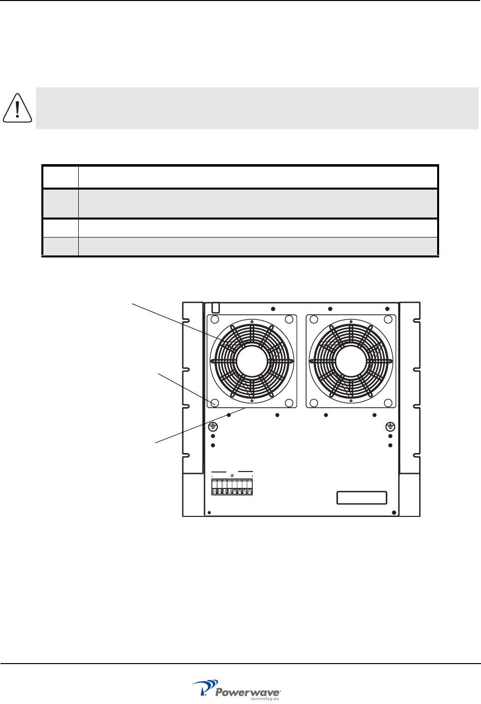
Rear Mount
Rear mounted fans may be changed without shutting down the system. To replace the fans, shown in Figure
4-3, perform the steps in Table 4-5.
Figure 4-3 Rear Mount Cooling Fan Removal and Replacement
CAUTION: The replacement fan may operate when the power connector is connected.
Ensure that no objects (fingers, screwdrivers, etc.) intrude into the fan area.
Table 4-6 Rear Mount Cooling Fan Removal and Replacement Procedure
Step Action
1. At rear of subrack, pull out snap fasteners that secure defective fan assembly
to fan-mounting bracket
2. Pull fan outward, and disconnect fan power connector
3. See Caution. Install replacement fan assembly in reverse order of removal
DC POWER
+27V RETURN
0 1 2 3 0 1 2 3
Cooling
Fan
Snap
Fasteners (4)
Power/Sense
Connector
Located Inside
Assembly
Field Replacement Procedures PAF-0813-E0-001
4-6 044-05287 Rev A
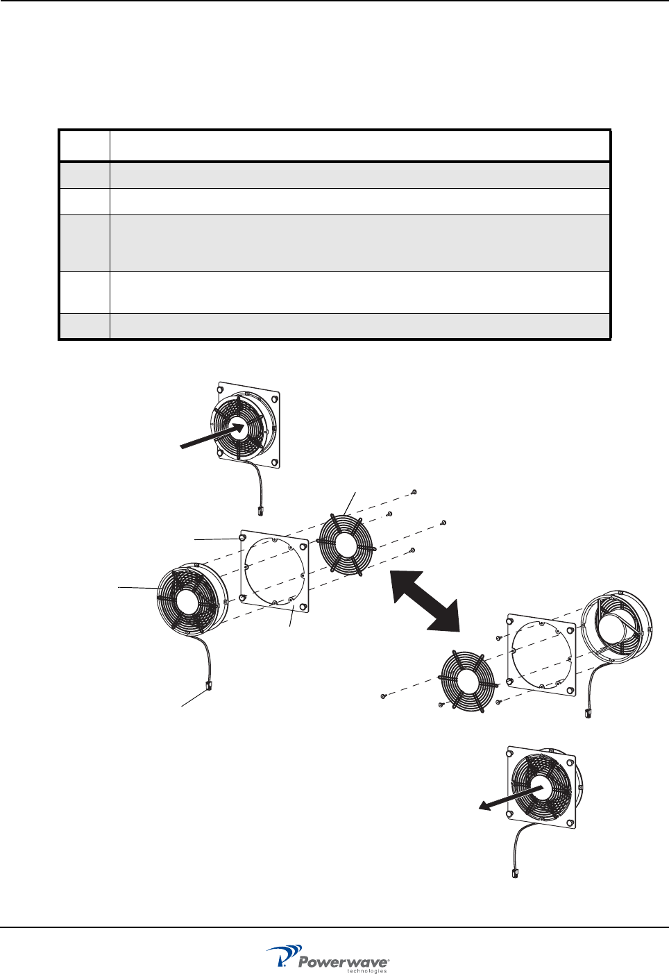
Fan Inside Mount to Rear Mount Conversion
To convert the subrack fan from inside mount to rear mount, as shown in Figure 4-4, perform the steps in
Table 4-6.
Figure 4-4 Fan Inside Mount to Rear Mount Conversion
Table 4-7 Fan Conversion Procedure
Step Action
1. To remove fan assembly from subrack, follow steps listed in Table 4-5
2. Disassemble inside mount fan assembly as shown in Figure 4-4
3. Reassemble inside mount fan assembly into rear mount configuration shown in
Figure 4-4. Maintain orientation of fan to ensure air is exhausting out rear of
subrack
4. Connect power connector, place fan assembly into mounting position, then
press each snap fastener to secure fan to subrack
5. Repeat Steps 1 through 4 for second fan
Mounting
Bracket
Snap
Fasteners
Fan
Grill
Inside Mount
Rear Mount
Fan Assembly
Fan Assembly
Power
Connector
Air
Flow
Air
Flow
PAF-0813-E0-001 Field Replacement Procedures
044-05287 Rev A 4-7
Subrack
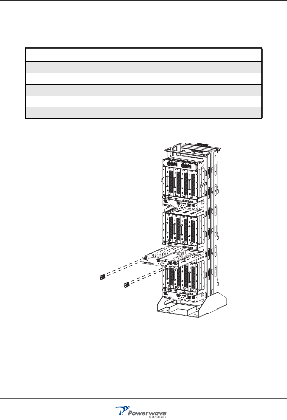
To remove and replace the subrack, shown in Figure 4-5, perform the steps in Table 4-7.
Figure 4-5 Subrack Removal and Replacement
CAUTION: Support rear of Subrack when removing from rack. The subrack may disengage
suddenly from the sliding brackets.
Table 4-8 Subrack Removal and Replacement Procedure
Step Action
1. At affected subrack, set all MCPA OFF/ON/RESET switches to OFF
2. At breaker panel, set all subrack associated circuit breakers to OFF
3. Disconnect all semi-rigid RF cables between subrack and duplexer
4. Disconnect subrack alarm cables
5. At rear of subrack, label and disconnect all breaker panel DC power connections,
maintaining DC Power cable service loop
6. Remove four mounting screws from both sides of subrack
7. Slide subrack forward out of frame until completely disengaged from sliding brackets.
Ensure rear of subrack is supported to prevent subrack from suddenly disengaging
8. Install new subrack in reverse order of removal
DC POWER
+27V
RETURN
01230123
STATUS
RESET
STA
TUS
RESET
STATUS
RESET
PC I/O PC I/O
PC I/O
STATUS
RESET
PC I/O
Alcatel Lucent Alcatel Lucent Alcatel Lucent Alcatel Lucent
Subrack
Four screws located
on both sides of subrack
DC power
connection
s
Field Replacement Procedures PAF-0813-E0-001
4-8 044-05287 Rev A
Filter
To remove and replace the filter, shown in Figure 4-6, perform the steps in Table 4-8.
Figure 4-6 Filter Removal and Replacement
Table 4-9 Filter Removal and Replacement Procedure
Step Action
1. At subrack, set all MCPA OFF/ON/RESET switches to OFF
2. At breaker panel, set all circuit breakers to OFF
3. Disconnect and tag all cables from filter
4. Remove four screws securing filter to shelf
5. Install new filter in reverse order of removal
OFF
PC I/O
850 MHz
STATUS
RESET
ON
Alcatel Lucent
OFF
PC I/O
850 MHz
STATUS
RESET
ON
AlcatelLucent
OFF
PC I/O
850 MHz
STATUS
RESET
ON
Alcatel Lucent
OFF
PC I/O
850 MHz
STATUS
RESET
ON
Alcatel Lucent
OFF
PC I/O
850 MHz
STATUS
RESET
ON
Alcatel Lucent
OFF
PC I/O
850 MHz
STATUS
RESET
ON
Alcatel Lucent
OFF
PC I/O
850 MHz
STATUS
RESET
ON
Alcatel Lucent
OFF
PC I/O
850 MHz
STATUS
RESET
ON
Alcatel Lucent
OFF
PC I/O
850 MHz
STATUS
RESET
ON
Alcatel Lucent
OFF
PC I/O
850 MHz
STATUS
RESET
ON
Alcatel Lucent
OFF
PC I/O
850 MHz
STATUS
RESET
ON
Alcatel Lucent
OFF
PC I/O
850 MHz
STATUS
RESET
ON
Alcatel Lucent
PAF-0813-E0-001 Field Replacement Procedures
044-05287 Rev A 4-9
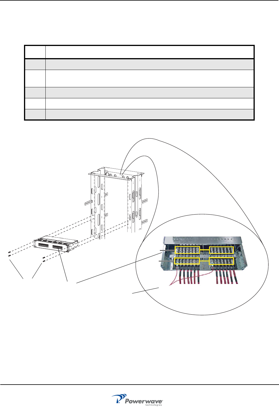
Circuit Breaker Panel
To remove and replace the circuit breaker panel, shown in Figure 4-9, perform the steps in Table 4-11.
Figure 4-7 Breaker Panel Unit Removal and Replace
Table 4-10 Circuit Breaker Panel Removal and Replacement Procedure
Step Action
1. Turn off all +27 VDC BTS input power to PAF system
2. Label and disconnect all input and output DC power connections from top rear
of circuit breaker panel
3. Remove screws from circuit breaker panel
4. Remove circuit breaker panel from PAF frame
5. Install circuit breaker panel replacement in reverse order of removal
Power in from
base station
Power out to
subracks
Circuit breaker panel
input and output
DC wiring
Circuit
Four screws
panel
Breaker

Return For Service Procedures PAF-0813-E0-001
4-10 044-05287 Rev A
Return For Service Procedures
When returning products to Powerwave, the following procedures will ensure optimum response.
Obtaining An RMA
A Return Material Authorization (RMA) number must be obtained prior to returning equipment and to reduce
delays in receiving repair service. Please contact our Repair Department at rma@pwav.com, (714) 466-1000
to obtain this number, or FAX your request to (714) 466-5816. For 24-hour technical support, call 1-800-473-
1720 and select option 3.
Repackaging For Shipment
To ensure safe shipment of a component, it is recommended that the original packing materials be reused. If
not possible, use suitable shipping cartons and foam inserts to prevent damage in transit.
044-05287 Rev A 5-1
Chapter 5
Specifications
Introduction
This chapter provides system specifications that support the PAF-081X-P0-001 MCPA system. The system
specifications are listed in Table 5-1.
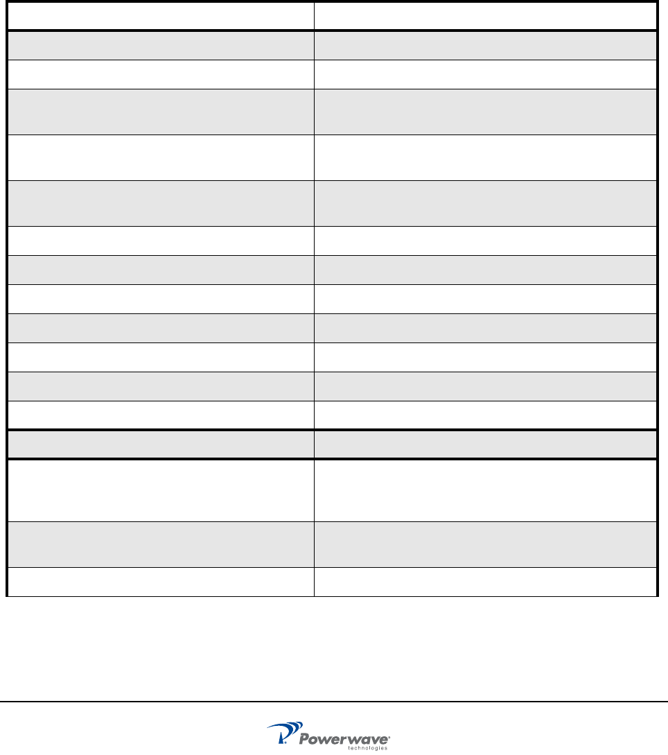
Figure 5-1 System Specifications
Electrical Specifications/Features
Downlink Frequency Range 869-894 MHz
Uplink Frequency Range Cellular (850) = 824-849 MHz
RF Power Output per Antenna Port
Measured @ Alpha, Beta, and Gamma Bulkheads
468 watts (56.7 dBm) per sector nominal AMPS
381 watts (55.8 dBm) per sector nominal CDMA
Air Interface Compatible with most standards for: TDMA, GSM, EDGE,
CDMA, W-CDMA
Max Input Power Handling
(Composite RF per port)
0dB peak
Emissions Limits Compliant to FCC Part 15, class B, Part 22 Cellular
Gain Variation vs. Frequency and Power ±0.6dB
Gain Variation vs. Temperature ±0.5dB for temperatures ranging from -5 to +45 oC
Input Port Return Loss 14 dB
Output Port Return Loss 14 dB
Operating DC Voltage Range 21 – 30 VDC
Alarms RS485; Minor, Major, and Critical
Mechanical Specifications/Features
PAF Connectors Antenna Ports (Alpha, Beta, Gamma) Type 7/16 DIN
Input Ports J1 - J6 Type - SMA
Alarms, RS-486
Weight (3 sectors) Empty: 428 lbs (194 kg)
Loaded: 588 lbs (267 kg)
Dimensions (W x D x H) 22.75 (577.85 mm) x 26.5 (673.1 mm) X 78 (1981.2 mm)
Introduction PAF-0813-E0-001
5-2 044-05287 Rev A
Torques (Inch-Pounds):
Metal Machine Screws
8-32
10-32
1/4-20
5/16-18
Coaxial Connectors
SMA
Type N
Type 7/16 DIN
20 to 24
32 to 40
70 to 80
140 to 160
5 to 6
12 to 15
220 to 230
Environmental Specifications/Features
Operating Temperature Range -5 - +45o C
Operating Humidity Range 5 -100% RH @ +40o C, Non-Condensing
Altitude -60 to 4000 meters
Seismic GR-63-CORE, Section 4.4.1, Zone 4
Lightning Surge Protection 3 kA @ 10/350 us waveform
5 kA @ 8/20 us waveform
Office Vibration GR-63-Section 5.4.2
Transportation Bump IEC 60068-2-29, Eb, 100 bumps per axis
Transportation Shock IEC 60068-2-27, Ea, three 15 g, 11 ms, half-sine shocks, Z
axis
Figure 5-1 System Specifications (Continued)

Corporate Headquarter
s
P
owerwave Techno
l
1801 East St. Andrew Place
Santa Ana, CA 92705 USA
Tel: 714-466-1000
Fax: 714-466-5800
www.powerwave.com
Main European Office
Antennvägen 6
SE-187 80 Täby
Sweden
Tel: +46 8 540 822 00
Fax: +46 8 540 823 40
Main Asia -Pacific
Office
23 F Tai Yau Building
181 Johnston Road
Wanchai, Hong Kong
Tel: +852 2512 6123
Fax: +852 2575 4860
©Copyri
g
ht 2007, Powerwave Technolo
g
ies, Inc. All Ri
g
hts reserved. Powerwave, Powerwave Technolo
g
ies, The Power in Wireless and the Powerwave lo
g
o are re
g
istered trademarks of Powerwave Technolo
g
ies, Inc.
Powerwave Installation and Service Manual