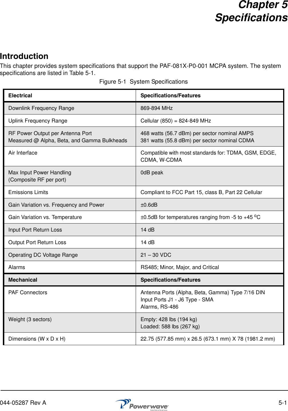
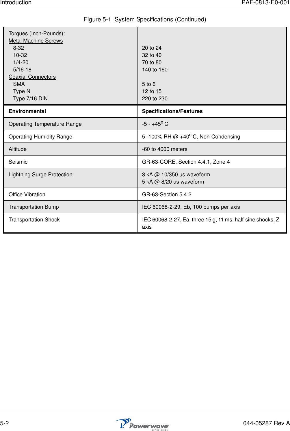
Powerwave Technologies 5JS0097 RF Power Amplifier Frame User Manual 044 05287 PAF 0813 E0 001
Powerwave Technologies Inc RF Power Amplifier Frame 044 05287 PAF 0813 E0 001
UserManual.wiki
>
Powerwave Technologies
>
5JS0097 User Manual
>
Users Manual Part 2
Contents
1.
Users Manual Part 1
2.
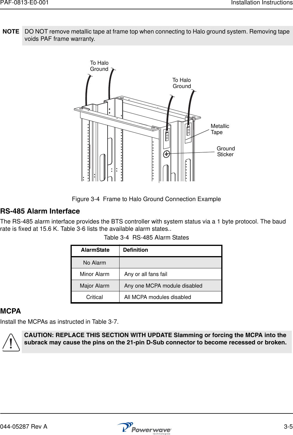
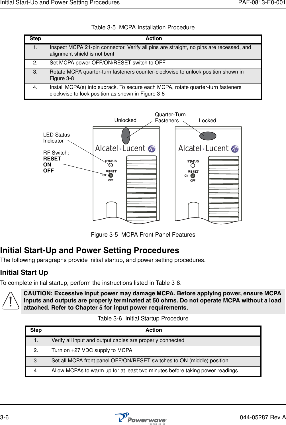
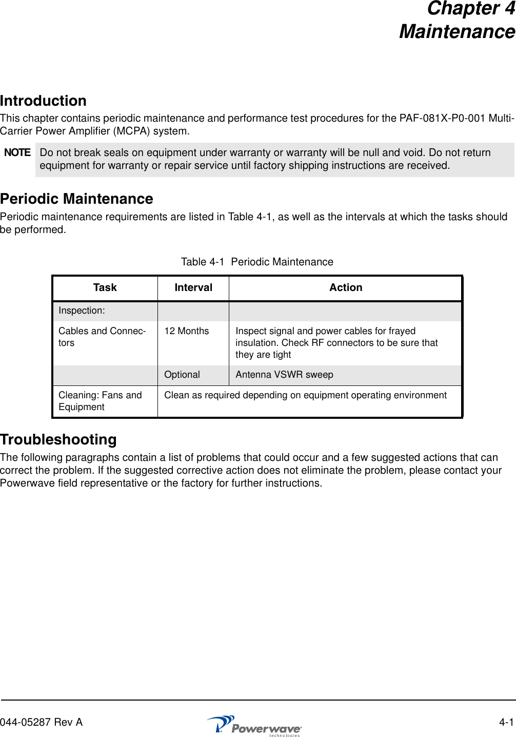
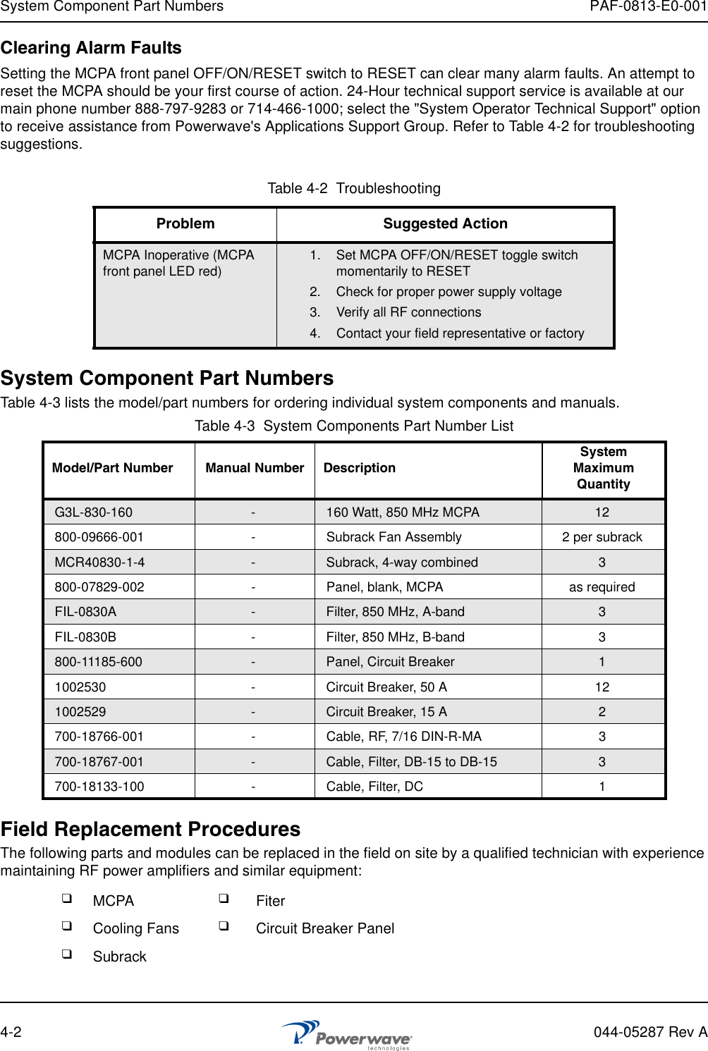
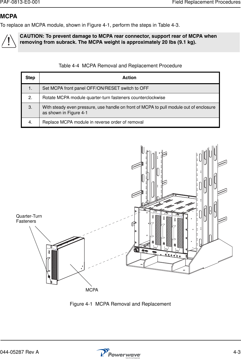
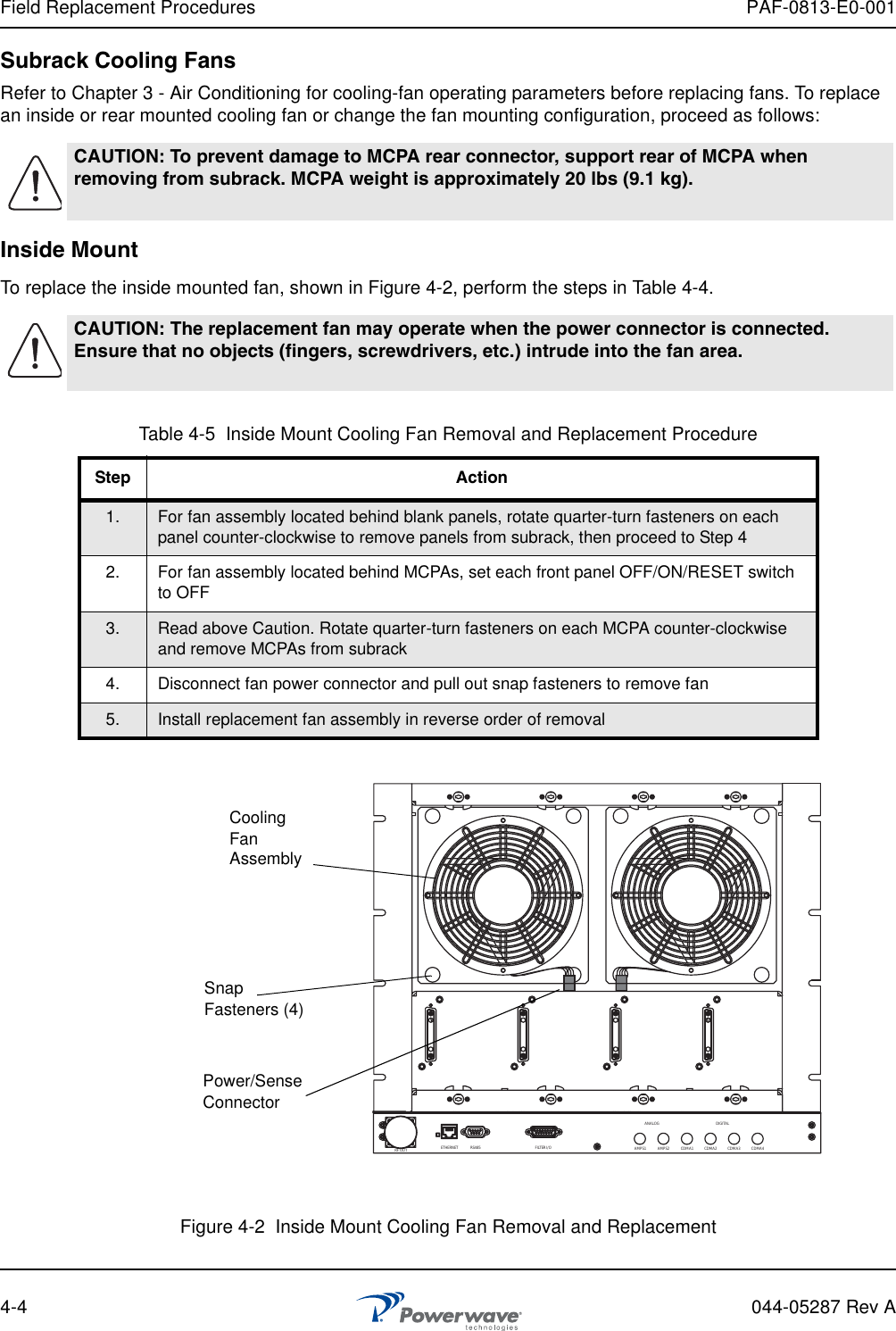
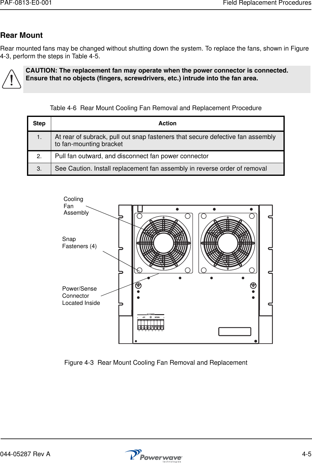
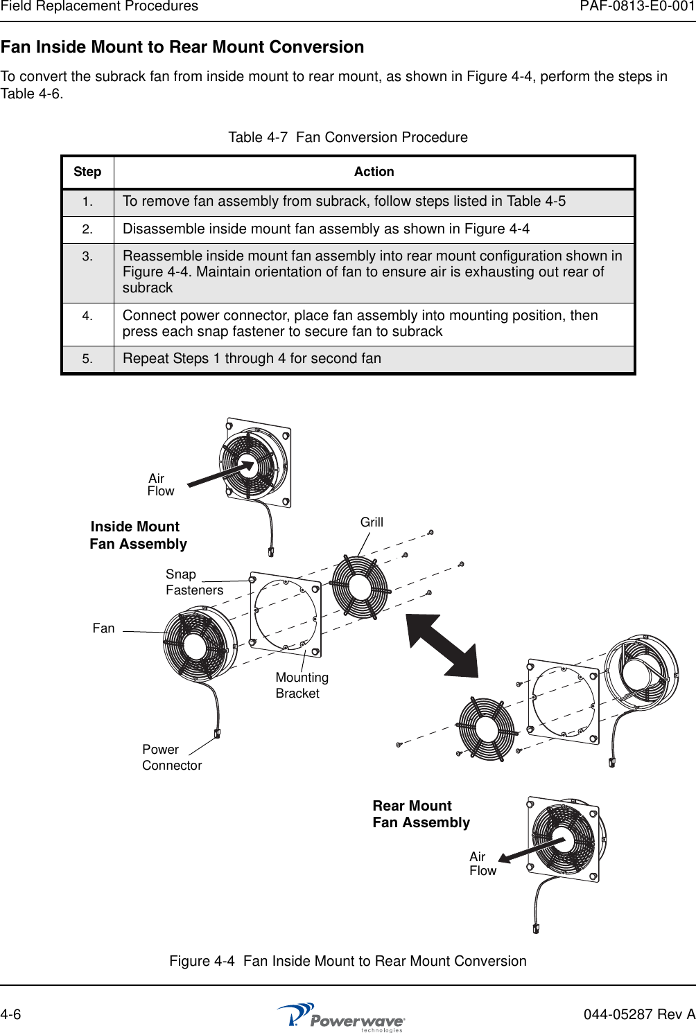
Users Manual Part 2
Users Manual Part 2
Navigation menu
Upload a User Manual
Namespaces
Wiki Guide
HTML
PDF
Info
Views
User Manual
Discussion / Help
Navigation