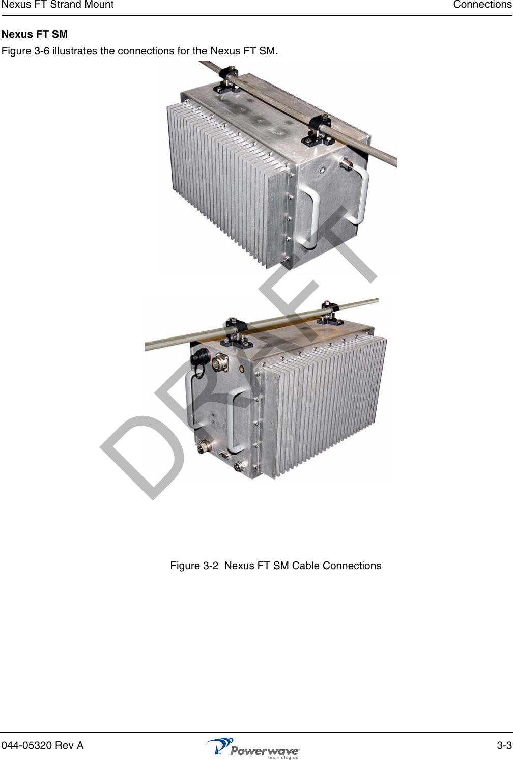
Powerwave Technologies 5JS0103 Nexus Strand Mount User Manual 044 05320 FT Strand Mount

Powerwave Technologies Inc Nexus Strand Mount 044 05320 FT Strand Mount

Users Manual

044-05320 Rev A     June 2008DISTRIBUTED ANTENNA SYSTEMINSTALLATION AND SERVICE MANUALDASNEXUS FTSTRAND MOUNT      DRAFT
© 2008 Powerwave Technologies Incorporated. All rights reserved.Powerwave Technologies and the Powerwave logo are registered trademarks.Powerwave Technologies Inc. reserves the right to make changes to documentation and equipment, including but not limited to component substitution and circuitry changes. Changes that impact this document may be subsequently incorporated in a later revision of this document.This Powerwave product is designed to operate within the Normal Operating (typical operating) ranges or con-ditions specified in this document. Operation of this equipment beyond the specified ranges in this document may cause (1) spurious emissions that violate regulatory requirements; (2) the equipment to be automatically removed from service when maximum thresholds are exceeded; or (3) the equipment to not perform in accor-dance with its specifications. It is the Operator's responsibility to ensure this equipment is properly installed and operated within Powerwave operating specifications to obtain proper performance from the equipment and to comply with regulatory requirements.The rated output power of a FT Strand mount is for multiple carriers. As long as the composite power does not exceed the rated power (20W for North America), derating is not required for multiple carriers. For situations where regulatory requirements require reduced interference to adjacent band users, the rating would have to be reduced by 3 dB. This power reduction is to be by means of input power or gain reduction and not by an attenuator at the output of the device. Input power is rated at 115/230VAC, 50/60Hz, and should be protected based on the power and fuse specifications in Chapter 5 of this manual. Power strips should, at a minimum, conform to this requirement to prevent equipment damage and possible overload.Federal Communications Commission (FCC)This equipment has been tested and found to comply with the limits for a Class A digital device, pursuant to CRF47 part 15 of the FCC rules. This equipment is also certified to CRF47 part 24 (PCS) of the FCC Rules depending on the band of operation. Changes or modifications not expressly approved by Powerwave Tech-nologies, Inc. for compliance could void the user’s authority to operate this equipment. These limits are designed to provide reasonable protection against harmful interference when the equipment is operated in a commercial environment. This equipment generates, uses, and can radiate radio frequency energy and, if not installed and used in accordance with the instruction manual, may cause harmful interference to radio commu-nications. Operation of this equipment in a residential area is likely to cause harmful interference in which case the user will be required to correct the interference at his own expense. This device complies with the technical standards governing mobile radio devices in accordance with FCC Rules.  This device is intended to facilitate the reception and transmission of mobile radio devices in the cellu-lar, PCS or other mobile services, and its operation by end users or others requires carrier consent under FCC rules.Industry Canadian RequirementsAll Powerwave apparatus introduced in the Canadian market meet all requirements of the Canadian Interfer-ence-Causing Equipment Regulations. The -20dB bandwidth at 1900 MHz band is 80 MHz. The output imped-ance of the unit referenced in this document is 50 Ohms. The input signal is optical so input impedance requirements are not applicable.Powerwave Technologies Inc., 1801 East St. Andrew Place, CA 92705 Santa Ana, USA.Phone +1 714 466 1000 – Fax +1 714 466 5800 – Internet www.powerwave.comDRAFT
Nexus FT Strand Mount Warnings, Cautions, and Notes044-05320 Rev A iRevision Record Revision Letter  Date of Change Reason for ChangeA June 2008 New (original)DRAFT
Warnings, Cautions, and Notes Nexus FT Strand Mountii 044-05320 Rev AThis page intentionally left blankDRAFT
044-05320 Rev A viiPrefaceSafetyAny personnel involved in installation, operation, or service of units included in a Powerwave Distributed Antenna System (DAS) must understand and follow the points below.❑Powerwave Nexus FT systems are designed to receive and amplify signals from one or more base stations and retransmit the signals to one or more mobile stations. And, also to act the other way round, that is to receive signals from one or more mobile stations, amplify and retransmit the signals to the base stations. Powerwave Nexus FT systems must be used exclusively for this purpose and nothing else.❑Units supplied from the mains must be connected to grounded outlets and in conformity with the local prescriptions.❑Power supply units supplied from the mains contain dangerous voltage that can cause electric shock. Disconnect the mains prior to any work in such a unit. Local regulations are to be followed when servicing such units. Only authorized service personnel are allowed to service units while the mains are connected.❑All RF transmitting units, including Nexus FTs, will generate radio signals and thereby give rise to electromagnetic fields that may be hazardous to the health of any person who is extensively exposed close to an antenna.❑A lithium battery is permanently mounted on the CU and FON PCBAs. Due to the risk of explosion, this battery must only be removed from the board by a Powerwave authorized service technician.❑NiCd batteries are mounted on the FON PCBA. These batteries contain environmental poisonous substances. If replaced, the old batteries should be disposed of as stated in the local prescriptions.❑The FON unit contains a Class 1M laser transmitter that emits 2—4 mW invisible laser radiation at 1550 nm during operation and is intended for a restricted location. Avoid direct exposure from a disconnected laser transmitter or fiber cord. For example, do not view directly with optical instruments (magnifiers) and do not view directly with non-attenuating optical instruments.❑The FON Unit has this label attached:❑Do not power up the FON unit if a fiber cable is not connected to the fiber output UL port, or if a fiber cable is connected to the port but disconnected at the other end.❑Never look at the end of a fiber cable. The 1310nm and 1550nm laser light is not visible. Always use an instrument, such as a power meter, to detect signaling.DRAFT
Electrostatic Discharge (ESD) Nexus FT Strand Mountviii 044-05320 Rev AHuman Exposure to RF RadiationSafe distances must be kept when working around antennas. The following paragraphs describe the cautions to be aware of during the installation and maintenance of antenna systems and how to calculate safety distances needed for RF radiation at different antenna power and frequencies.AntennasTo be able to receive and transmit signals, a Nexus FT RM ORD is connected to a donor antenna directed towards the base station and a service antenna directed towards the coverage area. A fiber optic cable from the base station might, however, be substituted for the donor antenna.Installation and Maintenance of Antenna SystemsInstallation and maintenance of all antenna systems must be performed with respect to the radiation exposure limits for public areas. The antenna radiation level is affected by Nexus FT RM ORD output power, antenna gain, and transmission devices such as cables, connectors, splitters and feeders. Also have in mind the system minimum coupling loss, typically between 25dB and 35dB, is determined by a standard with the purpose to protect base stations from noise and other performance dropping effects.Radiation ExposureThe World Health Organization (WHO) and International Commission on Non-Ionising Radiation Protection (ICNIRP) have determined recommendations for radiation exposure. ICNIRP recommends not to exceed the following radiation power for public exposure:Frequency Radiation power800/900 MHz 4.5W/m²1800/1900 MHz 9.0W/m²2100 MHz 10.0W/m²For antennas larger than 20cm the maximum radiation power can be calculated by using the following formula:Electrostatic Discharge (ESD)ESD can severly damage essential parts of the equipment if not handled carefully. Parts on printed circuit board assemblies (PCBA) as well as other parts in the equipment are sensitive to ESD. Never touch the PCBA or uninsulated conductor surfaces unless absolutely necessary.If you must handle the PCBAs or uninsulated conductor surfaces, use ESD protective equipment or first touch the chassis with your hand. Never let your clothes touch PCBAs or uninsulated conductor surfaces and always store PCBAs in ESD-safe bags.S= P/(4πr2)S = Radiation power in W/m²P = Output power in Wr = Distance between antenna and human in metersDRAFT
044-05320 Rev A 1-1Chapter 1Product DescriptionIntroductionThis manual contains information and procedures for installation, operation, and maintenance of the Nexus FT Strand Mount repeater, referred to in this manual as the Nexus FT SM. The manual is organized into chapters as follows:Scope of ManualThis manual is intended for use by service technicians familiar with similar types of equipment. It contains service information required for the equipment described and is current as of the printing date. Changes which occur after the printing date may be incorporated by a complete manual revision or alternatively as additions.OverviewPowerwave Nexus FT SM repeaters work as bi-directional on-frequency amplifiers used to extend coverage into uncovered areas in wireless mobile systems such as base station fringe areas, tunnels, convention centers, airports and buildings. It receives, amplifies, and transmits signals to/from a Base Transceiver Station (BTS) to/from Mobile Stations (MS) with both directions being served simultaneously. Connections to the Nexus FT SM are made with N-type or 7/16" male connectors.Nexus FT SMs are microprocessor controlled. Operational parameters, such as gain and power levels are set using a PC running Powerwave OM-Online software which communicates with the Nexus FT SMs either locally or remotely via modem. Remote operation can be performed via PSTN or a GSM net. The Operation and Maintenance System (OMS) provides for Network Operations Center (NOC) configuration and alarm monitoring.Nexus FT SMs can be configured in many combinations depending on the wireless system, single or double system operation, and output power..❑Chapter 1 - Product Description❑Chapter 2 - Controls and Indicators❑Chapter 3 - Installation❑Chapter 4 - Maintenance❑Chapter 5 - SpecificationsDRAFT
Overview Nexus FT Strand Mount1-2 044-05320 Rev AChassis DesignEnclosureThe Nexus FT SM is housed in an aluminum enclosure, approved for outdoor use. The enclosure contains the repeater circuitry, with 2 hanger clips for positioning and securing the Nexus FT SM repeater along a cable. Figure 1-1   Nexus FT SM RepeaterDRAFT
044-05320 Rev A 2-1Chapter 2Controls, and IndicatorsIntroductionThis chapter contains descriptions of the controls, indicators and connectors for the Nexus FT SM. IndicatorsFigure 2-1   External IndicatorsTwo LEDs, shown in Figure 2-1, are located on the front cover to provide easy identification of a fault in the system. The amber operation LED lights up approximately 15 seconds after the main power is switched on. When the LED is steady, the Nexus FT SM is ready for operation. The red alarm LED indicates a system error alarm when flashing and a critical alarm when steady.Cabinet IndicatorsFigure 2-2   Cabinet Internal IndicatorsFONFigure 2-7 shows the locations of the connectors on the FON and Table 2-7 lists the port numbers, connector types, and port usage. DRAFT
Software and Hardware Compatibility Nexus FT Strand Mount2-2 044-05320 Rev ASoftware and Hardware CompatibilityThere are different versions of CU PCBA software which can be combined with PCBAs of various revisions. These have unique part numbers and revision information. Table 2-8 lists the software currently available in combination with CU PCBA revisions.Table 2-2  Hardware / Software CompatibilityThis information is accurate as of 06/31/2007. As new versions of hardware and software are released without prior notice, contact your Powerwave sales representative for information on the latest revision.For detailed information, refer to the release notes for the CU software to be downloaded (normally found in the readme.txt file provided with the program files).Table 2-1  FON ConnectorsPort DescriptionP101 SMA, electrical RF input port (to the optical TX port)P102 SMA, electrical RF output port (from the optical RX port)P103 SMA, electrical RF output port (15dB below the P102 port)RX DIN/APC, optical input port (to the P102 and P103 RF ports)TX DIN/APC, optical output port (from the P101 RF port)P104 Used only for development and debuggingP105 4-pin male, door LED indicators. Used for the yellow and red LED indicators located on the front cabinet doorP106 9-pin D-sub female, RS-232 used for local PC communicationP108/116 6-pin male, parallel connected power ports for the FONP109 7-pin male, used for external alarm sensorsP110 W-link jumper, used to terminate units in a W-link. It has to be set in the parking state for all units except for the first and last units in a W-link. The Parking state (P) has the jumper between the center and bottom pins. The opposite state, with the jumper between the tip and center pins, terminates(T) the W-linkP111/112 5-pin male, WLI ports used for interconnecting nodes in WLI-nets (IP or R2R networks). They are identical and connected in parallel. One of the connectors is intended to be used from the previous node and the other connector to the next node in the network. Either can be used for the first and the last unit in the net chainP113 2-pin male, used for the on-PCBA backup batteriesP114 Backup power output jumper, sets the backup power output state. The OFF state has jumper between the center and left pins. This jumper has to be in the OFF state when used in an OCM. Otherwise, it shall be in the ON stateP115 3-pin male, intended for future useP117 SMA, electrical RF output port (15dB below the P101 port)P130 34-pin, 2-line male, RCU port used for connecting an RCU. The connector contains both the modem connection and RCU power supplyCU PCBA part number CU Software part number500-13817-001 (previously K103/3) D631-18072-001D631-18072-003DRAFT
044-05320 Rev A 3-1Chapter 3InstallationIntroductionThis chapter contains unpacking, inspection and installation instructions for installing and powering up the Nexus FT SM.Site SurveyPowerwave recommends that a site survey be performed prior to equipment ordering or installation. Performing a detailed site survey reduces or eliminates installation and turn-up delays. Pay particular attention to power plant capacity, cooling needs, floor space, and RF/DC cabling/breaker requirements. Cabinet dimensions and weights are listed in Chapter 5.Unpacking and InspectionThis equipment has been operated, tested, and calibrated at the factory. Carefully open containers to remove equipment. Retain all packing material that can be reassembled in the event unit must be returned to the factory. Perform the following steps:❑  Visually inspect equipment for damage that may have occurred during shipment. If possible, in the presence of the delivery person.❑  Check for evidence of water damage, bent or warped chassis, loose screws or nuts, or extraneous packing material in connectors.If equipment is damaged, file a claim with the carrier once the extent of any damage is assessed.If equipment must be returned to factory, please contact factory for a Return Material Authorization (RMA), see Chapter 4.Nexus FT SM LocationThe Nexus FT SM is designed with a weather proof outdoor cabinet that can be mounted without any kind of shelter from rain, snow or hail. The same unit can be installed indoors. A preferable site for the Nexus FT SM is a location free of obstructions, easily accessible and allows for proper air-flow and ventilation.If a Nexus FT SM is installed outdoors and can be exposed to direct sunshine, it is essential that air circulates around the Nexus FT SM with no obstacles. The operating temperature must not exceed 131°F (55°C). A shelter can be used to shade the Nexus FT SM from direct sunshine..MountingThe Nexus FT SM is designed for mounting on a cable using the hangar clips attached to the top of the unit.Figure 3-1  Cable MountingDRAFT
Connections Nexus FT Strand Mount3-2 044-05320 Rev AConnectionsThis section describes general examples of how to connect the input and output ports on the WRH. Main Power and GroundingLocal regulations need to be followed for the main power connection. Nexus FT SMs are approved in accordance with EN and UL/cUL regulations. This is, however, only valid if a classified power cord is used. For the Nexus FT SM to meet these regulations you must select one of the following classified and approved cord types:❑  EN – H 05 W5 - F HMR❑  UL – AWM Style 2587❑  CSA– AWM 1 A/B 11 A/BFor outdoor use, the power cord should meet at least IP65 encapsulation requirements. Do not turn the main power on until you are ready to commission the WRH.Fiber Optic and RF ConnectionsFiber optic and RF cable connections should be verified both internally and externally before powering up the equipment. This section illustrates the general internal connections of the Nexus FT SM. Verify these connections with the as-built drawings and documents for your specific system configuration. Table 3-1 lists the steps to add the external connections to the Nexus FT SM.Table 3-1  Cable Connection ProcedureWARNING: For Nexus FT SMs supplied from the main power source, the main outlet must be grounded.Step Action1234DRAFT
Nexus FT Strand Mount Connections044-05320 Rev A 3-3Nexus FT SMFigure 3-6 illustrates the connections for the Nexus FT SM.Figure 3-2  Nexus FT SM Cable ConnectionsDRAFT
Optional Connections Nexus FT Strand Mount3-4 044-05320 Rev AOptional ConnectionsAlarmsAlarm signals from external sensors are received by an ALI or RCI which forwards them to the CU. The RCI is used if the Nexus FT SM has an RCU, otherwise the ALI is used. The software on the CU can activate acoustic or visual alarms or direct the alarm to the P33 alarm port for forwarding via an RCU through OM-Online. Alarms can also be handled by the FON. Alarms are configured through OM-Online.CommissioningBefore proceeding, carefully read the Safety section and check all connections made during the installation. To fulfill the IP65 weather protective requirements, ensure cable strain relief bushings are properly tightened. Also, ensure gaskets at cable inlets and on the cabinet are properly fitted and not damaged.A Nexus FT SM can be configured locally with OM-Online by connecting a standard serial cable from the COM port on the PC to the P31 PC port (RS-232) located to the right in the cabinet as shown in Figure 3-9. The P31 PC port is described in Chapter 2. Details on using OM-Online are described in the OM-Online User Manual.Initial StartupTo complete the inital start-up of the Nexus FT SM, follow the steps listed in Table 3-3.Table 3-2  Initial Statup ProcedurePassive Intermodulation (PIM) TestingPIM is the non-linear effect of passive RF components in a desired RF transmission band. As higher per-carrier transmit power levels are applied to duplexed passive RF networks, PIM becomes an increasingly significant factor in potential receiver desensitization. A PIM tester may be used on the RF network prior to turn-on and commissioning of the unit, but if a PIM tester is not available, the following may be used:The following equipment is required to test for PIM:❑  Anritsu Site eMaster or equivilent RF Spectrum Analyzer❑  Agilent ESG4432B or equivilent Multi-Signal Generator (or commissioned BTS)❑  Guarateed/calibrated PIM load capable of handling 20W composite power❑  Low-PIM RF cable adaptors such as N-N female, Din male to N femaile, DIN-DIN, SMA-SMA female, and N male to SMA female❑  Installed and operational Nexus FT SM unit❑  Installed passive RF network under test❑  Torque wrenches for DIN and N connectorsTwo different types of setup are available, depeding on equipment availability and testing methods. Figure 3-10 shows PIM testing with two carriers over one Nexus FT SM, and Figure 3-11 shows PIM testing with one carrier over each of two Nexus FT SMs.Step Action1234DRAFT
044-05320 Rev A 4-1Chapter 4MaintenanceIntroductionThis chapter contains periodic maintenance and performance test procedures for the WRH.Periodic MaintenancePeriodic maintenance requirements are listed in Table 4-1, as well as the intervals at which the tasks should be performed.TroubleshootingThe sections that follow contain a list of problems that could occur and a few suggested actions that might correct each problem. If the suggested corrective action does not eliminate the problem, please contact your Powerwave field representative or help line for further instruction.Clearing Alarm FaultsTable 4-2 lists the alarms that can be generated in the WRH. Critical, Error and Warning alarms are sent automatically from a WRH-V to OM-Online, stored and then viewed in the Alarm window.Table 4-1  Recommended Periodic MaintenanceTask Interval ActionInspection of cables and connectors12 months Inspect power, RF and Fiber cables for signs of damage or wear (frayed insulation, cracks, punctures, etc.) Check connections to be sure they are tightOptional Perform cable sweepsClean equipment Clean as required depending on operating environmentTable 4-2  Alarm TroubleshootingID Alarm Text Alarm Unit Alarm Description1 Power PSU Critical PSU1 in the cabinet does not work properly. A sum signal from the PSU1 indicates that at least one voltage output has dropped. If no mains breakdown relay is used, then the alarm will also be sent at mains breakdownCeasing PSU1 in the cabinet works properly again. Ceasing is sent if the PSU1 works at start-up, and there is a corresponding critical PSU1 alarm logged in the Events log. The WRH-V will restart when the power is back and this alarm will be sentPSU Critical PSU2 in the cover does not work properly. A sum signal from the PSU2 indicates that at least one voltage output has dropped. If no mains breakdown relay is used, then the alarm will also be sent at mains breakdownDRAFT
Troubleshooting Nexus FT Strand Mount4-2 044-05320 Rev ACeasing PSU2 in the cover works properly again. Ceasing is sent if the PSU2 works at start-up, and there is a corresponding critical PSU2 alarm logged in the Events Log. The WRH-V will restart when the power is back and this alarm will be sentPower FON Error The FON 10 Volt charger voltage is below limit. Suggested remedy: Replace the FONCeasing The cause of the alarm has ceased2 WRH-V restartCU None Power on start, or user ordered reboot. Logged to indicate a normal power up, or a restart ordered by the operatorWarning Software error restart, 1st – 7th time. Restart 1st to 7th time during a 14 day period. The counter is reset every 14th day, counted from power upError Software error restart 8th – 10th time. Restart 8th to 10th time during the 14 day period. At the 11th time, the SW bank will be blocked and not used anymore until a user ordered reset is performed, or power is switched off/on3Mains breakdownExternal Critical The mains power is gone. Used with an external relay indicating mains breakdown. The external relay should be connected to External Alarm 1 and the WRH-V configured to indicate this alarm. If no relay is used, a mains breakdown will be reported as a PSU faultCeasing The mains power is back. Sent if there is a corresponding critical mains breakdown alarm logged in the Events Log. The WRH-V will restart when the power is back4 Alarm reset CU None Alarm reset by the user. All alarms are reset. The cause of the alarm will be re-evaluated and reported, if still active5 Local bus errorWBA #, MCPA#Error Error when communicating on the bus. The CU has no contact with the WBA, or MCPA PCBA, which is taken out of service6 Main bkd w backupExternal Error Used to indicate that the mains is no longer available. WRH-V is powered by external battery backup unit. Suggested remedy: Check the mains powerCeasing The cause of the alarm has ceased7Err in AD-converterWarning The analog-to-digital converter on the CU PCBA does not give reliable values8 New unit detectedNone Compared to the last power on, the CU has recognized at least one additional hardware unit9 Inst. unit lost Error Compared to the last power on, the CU lacks at least one hardware unit10 EEPROM errorCU Error EEP read or write fail. Data cannot be written or read from the EEPROM on the CU PCBA. User parameters are stored in the EEPROM11 Log memory faultError Log memory fault. Indicates that the log memory on the CU PCBA is faulty. The WRH-V will not work. Not available in all CU software versionsTable 4-2  Alarm Troubleshooting (Continued)ID Alarm Text Alarm Unit Alarm DescriptionDRAFT
Nexus FT Strand Mount Troubleshooting044-05320 Rev A 4-312 High temp CU Warning The CU PCBA temperature is higher than 90°CCeasing The CU PCBA temperature has fallen below 90°C13 REFO error Error Significant REFO drift or error detected by CU14 Ext REFO errorWarning Suggested remedy: Check the reference source and the cables15 CU battery faultCU Warning CU RAM battery fault. The battery for the RAM on the CU PCBA has a voltage outside the normal 2.7 to 3.5 Volt. An alarm may be initiated at start-up if the WRH-V has been stored out of power for a long time. Suggested remedy: Ensure jumper P3 on the CU PCBA is mounted to charge the batteryCeasing The cause of the alarm has ceased16 SW load error CU Error Software load error. An error has occurred during a software load process. The flash memory does not contain a proper software. Suggested remedy: Check the CU software using the OM-Online SW Manager. Do NOT restart the WRH17 Log cleared CU None Log memory has been cleared. The check sum in the Events Log memory is faulty. The log is cleared. Can be caused of a bad RAM battery backup or low voltage to the RAM18 RTC restarted CU None The time is changed by the operator (logged to keep track of changes made to the RTC)Warning Time reset to 1994-01-01. The RTC was unable to keep track of the time and did a reset. Suggested remedy: Ensure jumper P3 on the CU PCBA is mounted to charge the battery19 RTC error Error RTC does not operate. The CU has detected an error in the RTC operation which makes the time unreliable. Suggested remedy: Replace the CU PCBA20 Door open alarmExternal Config The door has been open 30 seconds without disabling the alarmCeasing The door has been closed 30 seconds, or the alarm is disabled21 External alarm 1External Config External alarm input EA1 active more than 1 secondCeasing External alarm input EA1 no longer active22 External alarm 2External Config External alarm input EA2 active more than 1 secondCeasing External alarm input EA2 no longer active23 External alarm 3External Config External alarm input EA3 active more than 1 secondCeasing External alarm input EA3 no longer active24 External alarm 4External Config External alarm input EA4 active more than 1 secondCeasing External alarm input EA4 no longer activeTable 4-2  Alarm Troubleshooting (Continued)ID Alarm Text Alarm Unit Alarm DescriptionDRAFT
Troubleshooting Nexus FT Strand Mount4-4 044-05320 Rev A30 No modem foundRemote ctrl None No modem found, that is no answer is returned on a poll string to the modem33 No connectionRemote ctrl None No connection at callback. The WRH-V has tried to call as many times as stated in the alarm call settings. No connection was established.Warning No connection at alarm call. The WRH-V has tried to call as many times as stated in the alarm call settings. No connection was established. This alarm does not generate a new attempt to report alarm by alarm call.34 Login failed None Invalid WRH-V password35 Remote connectionRemote ctrl None Modem connection to OM-Online opened. Not logged on CU2. Login Registry gives the same function and more information about CU236 Modem init failedRemote ctrl None Initiation string to modem not OK. The initiation string sent to the modem is not OK. The string may contain commands not recognized by the modem. An alarm might be sent anyway. Suggested remedy: Check the modem using the OM-Online or OMS modem debugger37 Remote timeoutRemote ctrl Warning The time limit of 20 minutes is exceeded without extending the timer. The modem connection is terminated by the WRH38 PIN code failedRemote ctrl Warning The PIN code sent to MS is incorrect. To unlock the MS/SIM card, the PUK code will probably be neededCeasing The cause of the alarm has ceased39 No phone detectedRemote ctrl Warning When using a PC-card together with the MS, the alarm indicates contact with the PC-card, but MS is not present or turned off. Note: A Nokia MS does not power-up after power failure. Suggested remedy: Ensure the cellular phone is connectedCeasing The cause of the alarm has ceased40 Battery fault RCU, FON chargerError The backup battery on the RCU or the FON PCBA does not work properly. Suggested remedy: Check cables or replace batteryCeasing The cause of the alarm has ceased42 Antenna isolationWBA #, Channel #, UL/DLWarning Low antenna isolation. The antenna isolation is lower than the gain set. Gain is reduced by 10dB – 13dB below the oscillation point. Suggested remedy: Decrease gain or increase antenna isolationError Low antenna isolation at lowest gain. The gain has been reduced as much as possible but the oscillation still remains. The amplifier is turned off. Suggested remedy: Decrease gain or increase antenna isolationCeasing Normal operation again, that is no oscillation can be detected 13dB above the gain set48 Battery backup faultExternal Error If a battery backup unit alarm is connected to external alarm 2, then the operator can configure the WRH-V to display this alarm when the battery backup unit indicates alarmTable 4-2  Alarm Troubleshooting (Continued)ID Alarm Text Alarm Unit Alarm DescriptionDRAFT
Nexus FT Strand Mount Troubleshooting044-05320 Rev A 4-5Remarks:The Door Open alarm requires an optional door switch described in the Door Open Alarm section of Chapter 3.The Main power breakdown alarm requires an optional relay described in the Main Power Breakdown Relay section of Chapter 3.Ceasing The cause of the alarm has ceased50 Fiberoptical errorFOT fiber opticsConfigurableIf a fiber unit alarm is connected to external alarm 3, then the operator can configure the WRH-V to display this alarm when the fiber optical unit indicates alarmCeasing The cause of the alarm has ceased70 Bad table alarmCU Error Requested table contains incorrect information (SW error)71 Table not foundCU Error Requested table not found in the database (SW or calibration error)72 Table database errorCU Error Table database not found (calibration error)80 Antenna SWR alarmDonor antenna service antennaError Too low antenna return loss, caused either by cables, connectors, or antenna problems. Suggested remedy: Check antenna and cablesCeasing The cause of the alarm has ceased90 FON power alarmFON RF Error A DC voltage on a FON PCBA is out of range. Suggested remedy: Replace the FON PCBA.Ceasing The cause of the alarm has ceased91 FON TxStable alarmFON RF Error Laser transmitter control loop voltage out of range. Suggested remedy: Replace the FON PCBACeasing The cause of the alarm has ceased92 FON RxLevel alarmFON Warning Received optical level is below any of the two limits (one for Warning and one for Error). Suggested remedy: Check optical cablesError Received optical level is below any of the two limits (one for Warning and one for Error). Suggested remedy: Check optical cablesCeasing The cause of the alarm has ceased93 FON SPI alarmFON F2F Error The SPI bus connection to the RF modem does not work properly. Suggested remedy: Replace the FON PCBA245 Not In Allowed AreaCU None WRH-V is moved from the operating area and the RF HW is switched on or offTable 4-2  Alarm Troubleshooting (Continued)ID Alarm Text Alarm Unit Alarm DescriptionDRAFT
Field Replaceable Units Nexus FT Strand Mount4-6 044-05320 Rev AField Replaceable UnitsThere are no field replaceabel components in teh Nexus FT Strand Mount repeater. If any components fail, please contact Powerwave for assistance.Return For Service ProceduresWhen returning products to Powerwave, the following procedures will ensure optimum response.Obtaining an RMAA Return Material Authorization (RMA) number must be obtained prior to returning equipment to the factory for service. Pease contact our Repair Department at +1-714-466-1000 to obtain this number, or FAX your request to +1-714-466-5800. Failure to obtain this RMA number may result in delays in receiving repair service.Repackaging for ShipmentTo ensure safe shipment of the unit, it is recommended that the original package designed for shipping the unit be reused. If it is not available, contact Powerwave’s Customer Service Department at 1-800-797-9283, +1-714-466-100 or by e-mail at support@pwav.com for packing material.DRAFT
044-05320 Rev A 5-1Chapter 5SpecificationsIntroductionThis chapter provides specifications for the Nexus FT SM.Table 5-1   Nexus FT SM SpecificationsElectricalFrequency band UL 1850 to 1910 MHz (PCS)1920 to 1980 MHz (UMTS)Frequency band DL 1930 to 1990 MHz (PCS)Max absolute delayGain adjustment range (in 1 dB steps)GainUplinkDownlinkVariationInstantaneous bandwidthUplink AGC limitDownlink AGC limitReturn LossDownlink, Spurious and Emissions levelDownlink powerNoise figure excluding fiber optic linkFiber-Optic Link BudgetReceiver input port return lossPower supply voltageMaximum Current Draw (Single Band)Maximum Current Draw (Dual Band)Recommended Fuse size Single BandDual BandPower consumptionDRAFT
Introduction Nexus FT Strand Mount5-2 044-05320 Rev AImpedanceInputOutputMechanicalDimensions (W x H x D in inches)NYC RepeaterNYC Outer ShellWeightService Antenna port connectorDonor Optical port connectorEnvironmentalOperating Temperature RangeAltitudeCasing classFiber Optic Node (FON)Bandwidth @ 3dBPower Consumption, totalWavelengthTransmit Max continuous RF inputOptical output power, two levelsRF attenuation settable by SW in 1dB stepsReceiveMax optic power inputRF attenuation settable by SW in 1dB stepsAlarm threshold level, settable warningAlarm threshold level, settable errorTable 5-1   Nexus FT SM Specifications (Continued)DRAFT
Introduction Nexus FT Strand Mount5-3 044-05320 Rev AThis page intentionally left blankDRAFT
  1801 East St. Andrew Place Santa Ana, CA 92705 USA Tel: 714-466-1000 Fax: 714-466-5800  www.powerwave.com Main European Office Knarramasgatan 7 8tr164 40 Kista, Sweden  Sweden Tel: +46 8 540 822 00 Fax: +46 8 540 824 91 Main Asia-Pacific Office 23 F Tai Yau Building 181 Johnston Road Wanchai, Hong Kong Tel: +852 2512 6123 Fax: +852 2575 4860 ©Copyright 2008, Powerwave Technologies, Inc.  All Rights reserved. Powerwave, Powerwave Technologies, The Power in Wireless and the Powerwave logo are registered trademarks of Powerwave Technologies, Inc.Powerwave Installation and Service ManualWorldwide Corporate HeadquartersDRAFT

Navigation menu