Powerwave Technologies 5JS0105 Booster Amplifier Assembly User Manual 044 05243 OS 1933 E3 003 Rev A
Powerwave Technologies Inc Booster Amplifier Assembly 044 05243 OS 1933 E3 003 Rev A
Contents
- 1. Users Manual Part 1
- 2. Users Manual Part 2
- 3. Users Manual Part 3
Users Manual Part 2

OS-1933-E3-003 Field Replaceable Parts and Modules
4-4 044-05243 Rev A
Field Replaceable Parts and Modules
The MCPAs, rectifier modules, Control Module, Modem, RF conditioning unit, door fan assemblies, and power
system fuses can be replaced in the field on site by a qualified technician with experience maintaining RF
power amplifiers and similar equipment.
Opening the front or rear doors, or both as appropriate, is required to perform the following maintenance
operations. Door latches are 1/4 turn and require a 10 mm hex socket wrench or nut driver to open.
Table 4-3 lists the model numbers and descriptions for ordering individual field replaceable system
components.
Table 4-3 Field Replaceable System Components
Model Number
Manual
Number Description
Quantity per
System
OS-1933-E0-000 N/A OS System w/o MCPAs, Rectifier and RFCU 1
G3L-1929-160-001 044-05305 Multi-Carrier Power Amplifier 1 to 3
1001308 N/A Rectifier Module 1 to 4
800-20160-002 N/A Fan Assembly, 300 cfm, Rear Door 1
800-24963-001 N/A Fan Assembly, 300 cfm, Front Door 1
INST-OS-1933-E0-000 N/A Controller 1
100-24370-001 N/A Integrated RF Conditioning Unit (RFCU) 1
100-10544-001 N/A Air Filter 2
100-07892-002 N/A Blank Panel MCPA As Required
100-24232-001 N/A Blank Panel, RFCU As Required
1004415 N/A Fuse, MIDI Time Lag, Automotive Bolt-down, 60A,
32 V, (Littelfuse)
As required
1004416 N/A Fuse, Fast Acting, Cartridge, 15A, 250V (Littelfuse) As required
Field Replaceable Parts and Modules OS-1933-E3-003
044-05243 Rev A 4-5
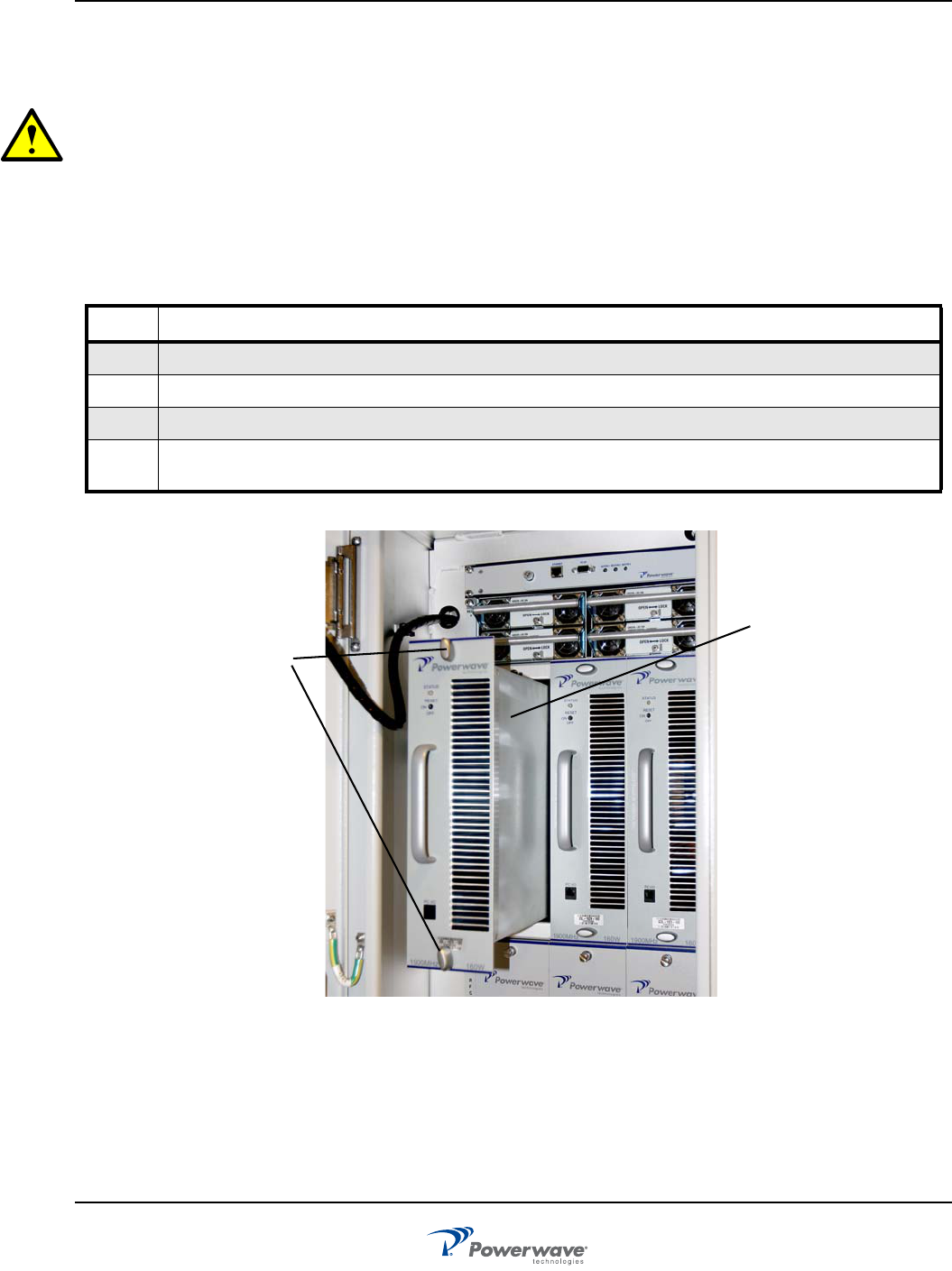
MCPA Removal and Replacement
Perform the instructions in Table 4-4 to remove and replace the MCPA shown in Figure 4-1 MCPA Removal
and Replacement.
CAUTION: When removing the MCPA from the subrack, support the rear of the MCPA to prevent a sud-
den drop when the guide rail disengages from the track. This could damage the rear multi-pin connector.
The MCPA weights approximately 20 lbs. (9.1 kg).
If an MCPA module is removed, another MCPA or blank panel must be installed in its place to provide ade-
quate cooling.
Always disable the MCPA of a sector prior to the removal of a MCPA or RFCU of that sector.
Table 4-4 MCPA Removal and Replacement Procedures
Step Action
1Set OFF/ON/RESET switch on front panel of MCPA down to OFF.
2 Rotate latches securing MCPA to subrack counterclockwise.
3With steady even pressure, use handle on front of MCPA to slide MCPA out of subrack.
4 Replace MCPA by carefully sliding MCPA into empty subrack slot. Secure MCPA by turning two latches
clockwise.
Figure 4-1 MCPA Removal
MCPA
Quarter-Turn
Fasteners
OS-1933-E3-003 Field Replaceable Parts and Modules
4-6 044-05243 Rev A
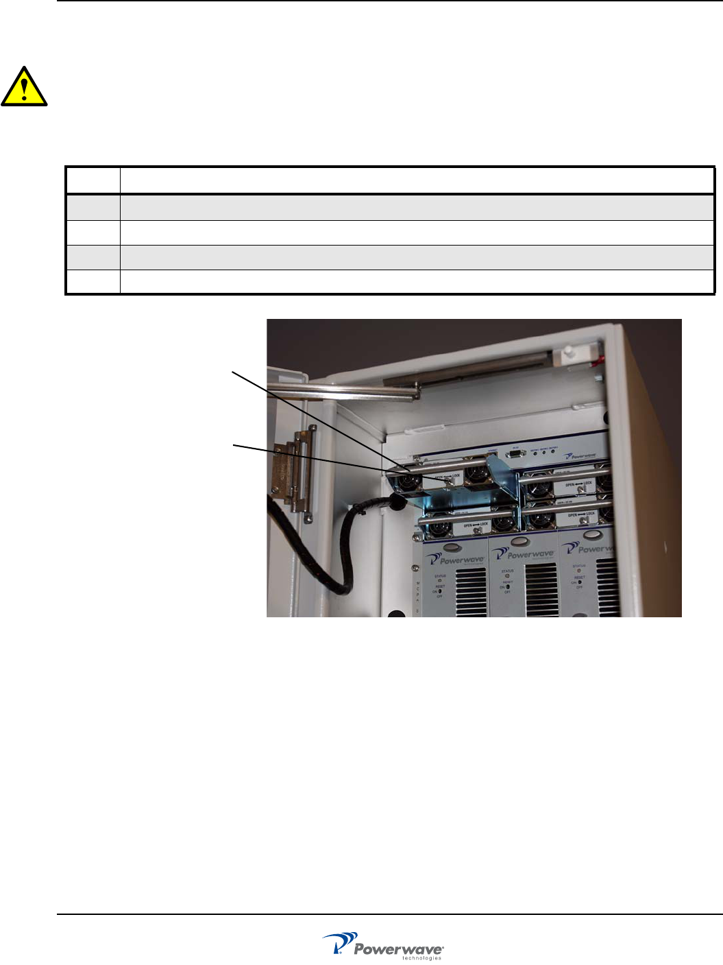
Rectifier Module Removal and Replacement
Perform the instructions in Table 4-5 to remove and replace the rectifier module shown in Figure 4-2
CAUTION: The rectifier module weighs approximately 5 lbs. (2.3 kg). When removing the rectifier module from
the subrack, support it at the rear when the guide rail disengages from the track to avoid dropping the module.
Dropping the rectifier module could damage the rear multi-pin connector.
Table 4-5 Controller Module Removal and Replacement Procedures
Step Action
1Using a #2 Phillips screwdriver, loosen the Phillips fastener securing the latch.
2 Slide and hold latch to left
3Use handle to carefully pull rectifier module out of cabinet
4 Replace rectifier by carefully sliding rectifier into empty slot until rectifier is secured
Figure 4-2 Rectifier Removal and Replacement
Rectifier
Latch
Field Replaceable Parts and Modules OS-1933-E3-003
044-05243 Rev A 4-7
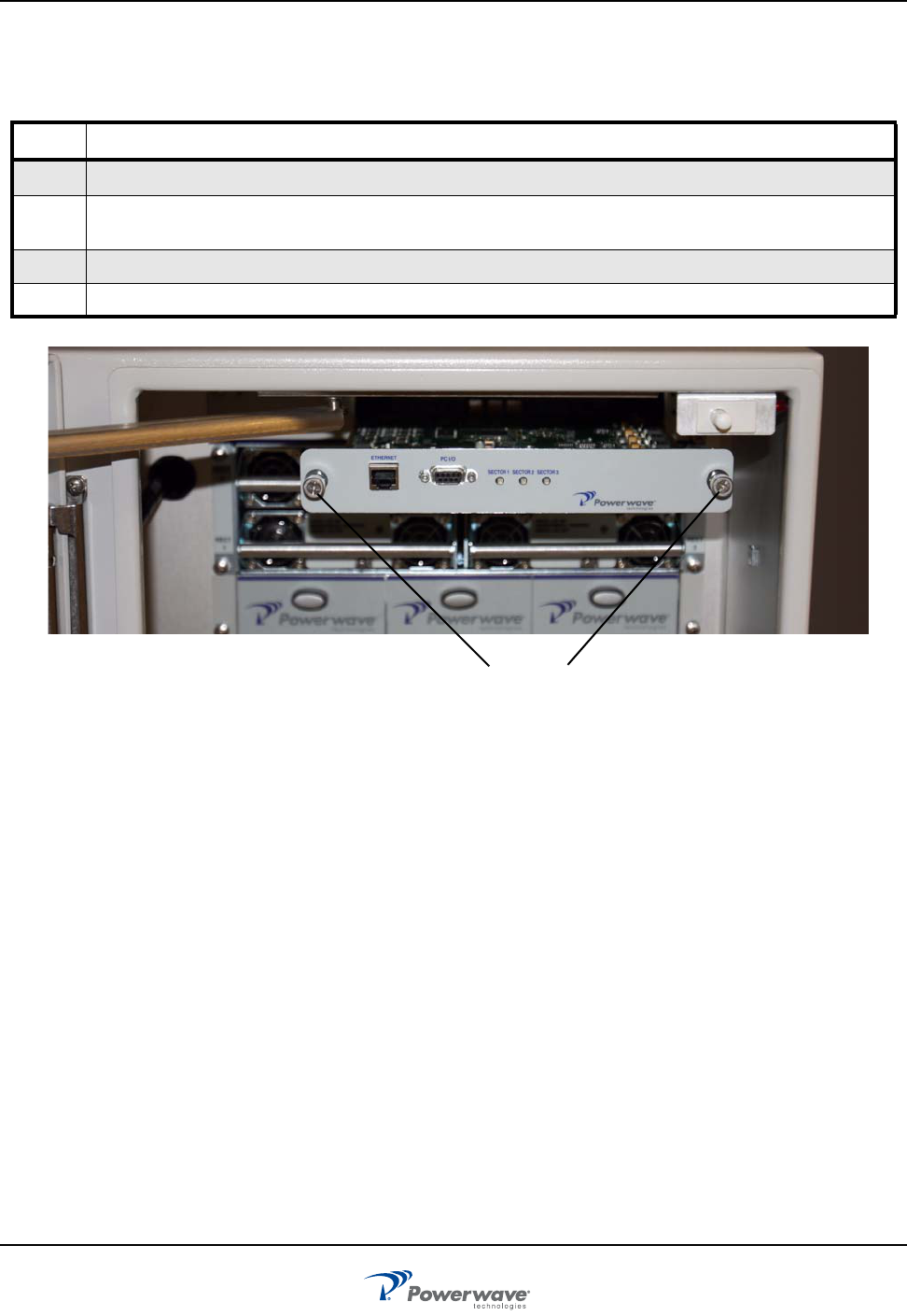
Controller Module Removal and Replacement
Perform the instructions in Table 4-6 to remove and replace the Controller Module shown in Figure 4-3.
Figure 4-3 Controller Module Removal and Replacement
Table 4-6 Controller Module Removal and Replacement Procedures
Step Action
1Remove external AC power from OS enclosure
2 With enclosure front access door open, rotate two thumbscrews counterclockwise to release Controller
Module
3Using two thumbscrews, pull Controller Module out of enclosure
4 Install new Controller Module in reverse order
Thumbscrews
OS-1933-E3-003 Field Replaceable Parts and Modules
4-8 044-05243 Rev A
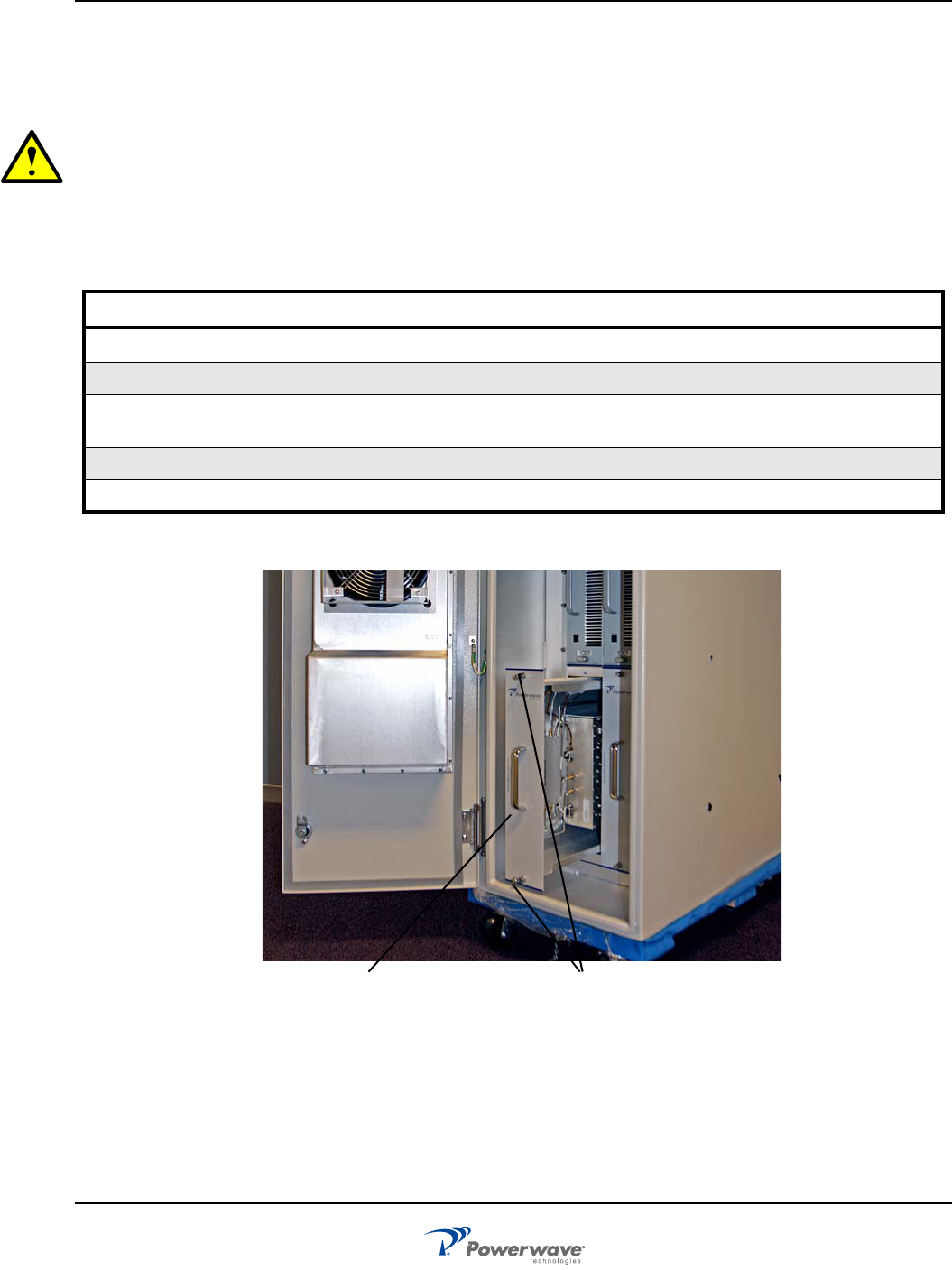
RF Conditioning Unit (RFCU) Removal and Replacement
Perform the steps listed in Table 4-7 to remove and replace the RF conditioning unit shown in Figure 4-4. The
RFCU unit contains unique calibration tables. The OS system will upload the tables to the Controller
automatically upon insertion.
CAUTION: The RFCU weighs approximately 40 lbs. (18.14 kg). When removing the RFCU Module from the
subrack, support it at the rear when the guide rail disengages from the track to avoid dropping the module.
Dropping the RFCU Module could damage the rear multi-pin connector.
Always disable the MCPA of a sector prior to the removal of a MCPA or RFCU of that sector.
Table 4-7 RF Conditioning Unit (RFCU) Removal and Replacement
Step Action
1Disable the MCPAs in the affected sectors.
2Disconnect external cables to RFCU interface in the affected sectors.
3 Using a slotted screwdriver with a 8mm (5/16 in) typical blade, loosen the top and bottom fasteners
securing the RFCU to the OS system.
4With steady pressure, use the handle on the front of the RFCU to slide the unit out of the OS system.
5 Replace RFCU in reverse order
Figure 4-4 RF Conditioning Unit Removal and Replacement
RFCU Fasteners
Field Replaceable Parts and Modules OS-1933-E3-003
044-05243 Rev A 4-9
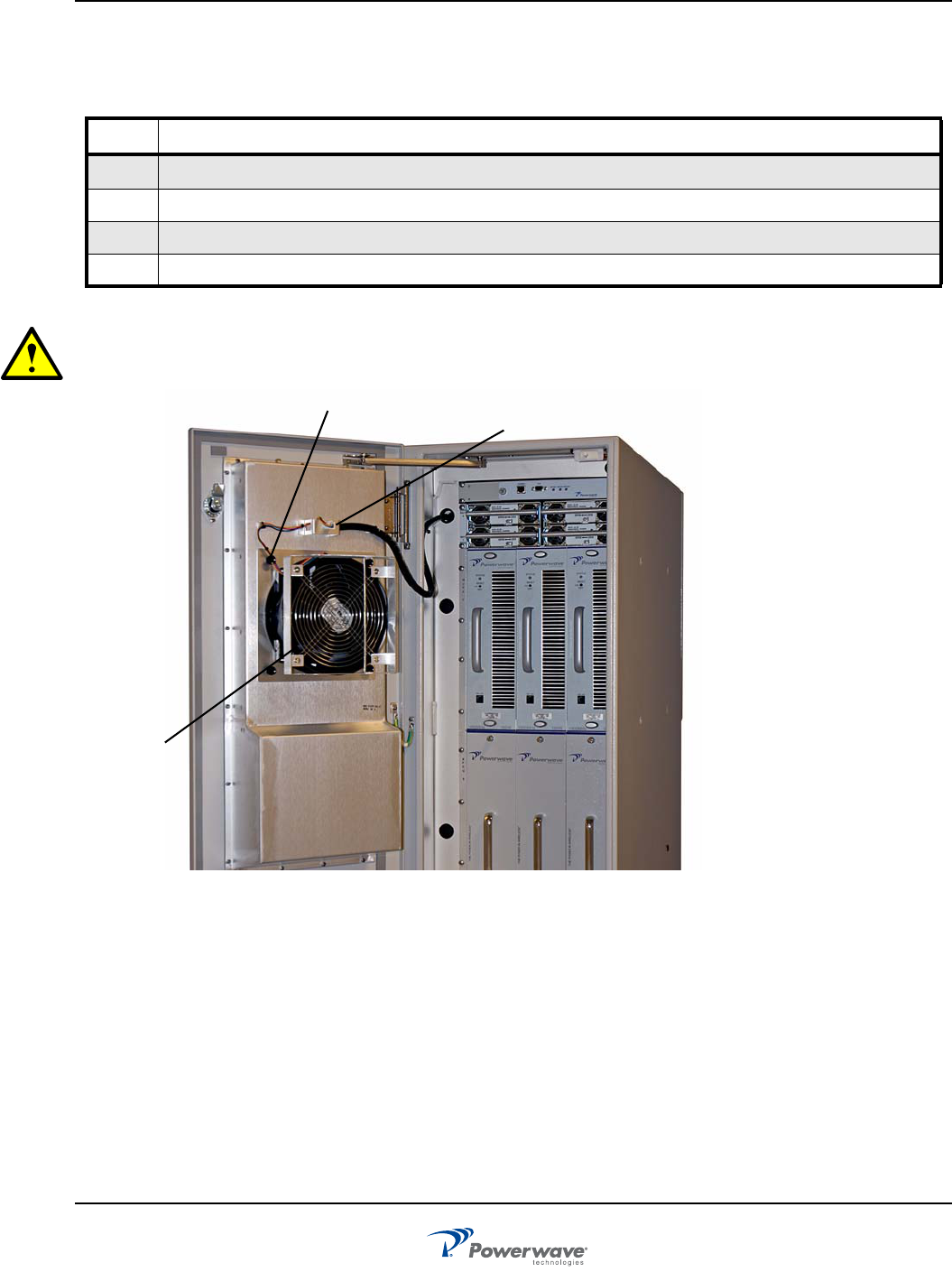
Fan Assembly Removal and Replacement
Perform the instructions in Table 4-8 to remove and replace the fan assembly shown in Figure 4-5.
CAUTION: Ensure the fan assembly is replaced by the correct type. Front fans and rear fans are assem-
bled different per air flow.
Figure 4-5 Fan Assembly Removal and Replacement
Table 4-8 Fan Assembly Removal and Replacement Procedures
Step Action
1Open appropriate cabinet door.
2 Disconnect fan connector.
3Pull out on four fasteners that secure fan assembly, then remove fan assembly.
4 Align fan assembly and push in fasteners to reattach fan assembly, then reconnect fan connector.
Fan Assembly
Connector
Fan
Fasteners (4)
OS-1933-E3-003 Field Replaceable Parts and Modules
4-10 044-05243 Rev A
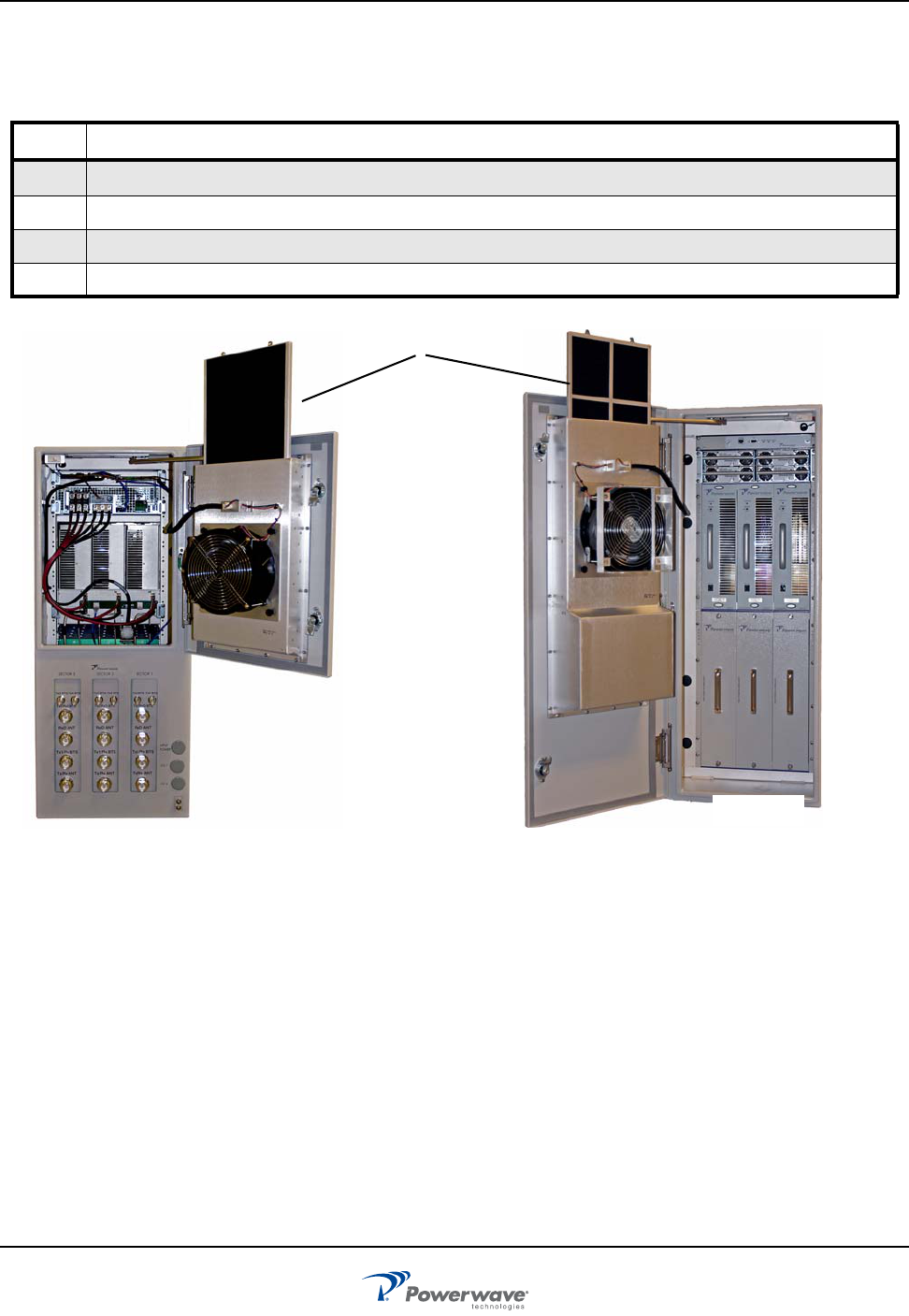
Air Filter Cleaning
Perform the instructions in Table 4-9 to clean the air filters shown in Figure 4-6.
Figure 4-6 Air Filter Removal, Cleaning, and Replacement
Table 4-9 Air Filter Cleaning Procedures
Step Action
1Open front door of OS. Fans power off automatically when door is opened
2 Pull up to remove air filter from OS
3Clean air filter using water spray or compressed air. Allow filter to dry if using water spray
4 Slide filter back into empty slot and secure front door
Air Filters
Field Replaceable Parts and Modules OS-1933-E3-003
044-05243 Rev A 4-11
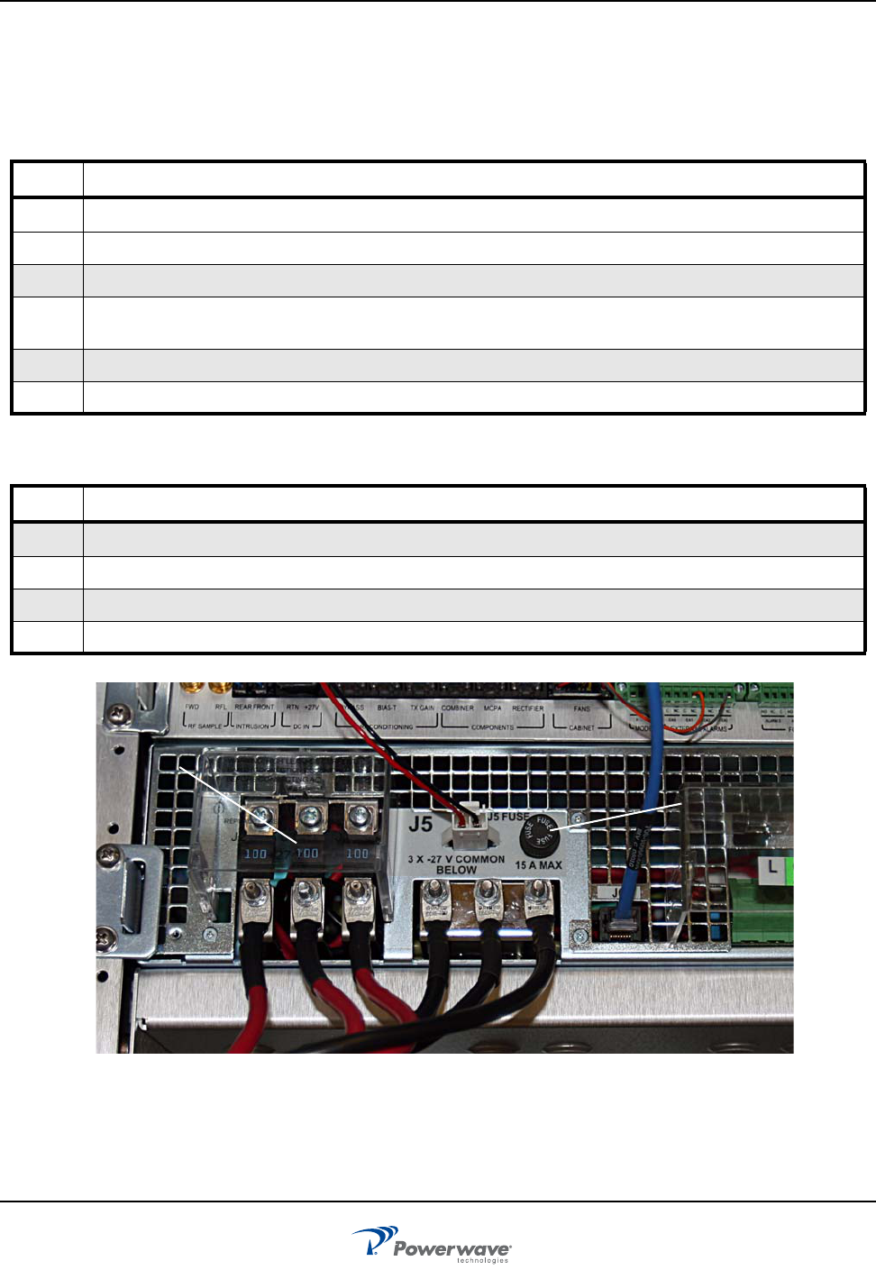
Power System Fuse Removal and Replacement
The fuses for the power system are located on the back panel as shown in Figure 4-7. Perform the instructions
in Table 4-10 to remove and replace the power system 60 amp DC fuses. Perform the instructions in
Table 4-11 to remove and replace the power system 15 amp fuse.
Figure 4-7 Fuse removal and replacement
Table 4-10 60-Amp Fuse Removal and Replacement Procedures
Step Action
1Remove AC to booster via external AC circuit breaker.
2 Open rear door of OS. Verify AC is removed.
3Pull up to snap open fuse protective cover.
4 Remove screws securing top of appropriate fuse. Remove hex nut and disconnect cable at bottom of fuse.
Verify replacement fuse has correct rating.
5Replace screws to secure fuse. Push up to close protective cover.
6 Close rear door of OS
Table 4-11 15-Amp Fuse Removal and Replacement Procedures
Step Action
1Open rear door of OS.
2 Remove screw-in fuse cap and remove fuse. Verify replacement fuse has correct rating.
3Replace fuse and replace fuse cap.
4 Close rear door of OS.
32 VDC 60 A Fuse (3)
(under cover)
250 VDC 15 A Fuse

OS-1933-E3-003 Field Replaceable Parts and Modules
4-12 044-05243 Rev A
This page intentionally left blank

044-05243 Rev A 5-1
Chapter 5
Specifications and Drawings
Introduction
The performance and physical specifications for the OS-1933-E0-003 Outdoor Multi-Carrier Power Amplifier
(MCPA) System are listed in Table 5-1. Outdoor System (OS) dimensions and installation examples are shown
in Figures 5-1 through 5-4.
Table 5-1 Outdoor System Specifications
Electrical Specifications/Features
Tx Frequency Ranges 1930 MHz to 1990 MHz
Rx Frequency Range 1850 MHz to 1910 MHz
Output Power (typical) 115W (50.97 dBm) per sector
375W total per site
Instantaneous Bandwidth 60 MHz
Air Interface 3GPP TS45.005, 25.141
Frequency Separation 1.25 MHz minimum, 40 MHz maximum
Input Power from BTS +47 dBm maximum per port
Intermodulation -62 dBc
Bypass Insertion Loss <1.0 dB, TX and RX
Receive Band Insertion Loss Adjustable RX gain from G < 0dB to G > 12dB
TX Rejection in RX Band -115dBm/100kHz
Impedance, All Ports 50 ohms, 14 dB RL
Alarms Form-C, wireless modem (optional)
RF Bypass (Alarm and Power Outage) Included
TX Gain Range (typical) Adjustable:
Min < 0, Max >17dB TX1 - Ant
Min < 0, Max >17dB TX2 - Ant
Min < 0, Max >17.8dB TX3 - Ant
Min < 0, Max >17.8dB TX4 - Ant
Gain Flatness 1.5 dB, peak to peak maximum
Lightning Protection 20 kA EIC 61000-4-5 8/20 US waveform
Operating Voltage AC: 180 to 264 VAC (220 VAC typical), single phase, 47 to
63 Hz (60 Hz typical)

OS-1933-E3-003 Introduction
5-2 044-05243 Rev A
Mechanical Specifications/Features
Input RF Connector 7/16 DIN
Output RF Connector 7/16 DIN
AC Power Connection Screw terminal barrier block (5-20 AWG)
Housing IP55 IP rating
Dimensions Refer to Figure 5-1 Outdoor System Dimensions
Weight populated 175 kg (386 lbs)
Minimum Clearances Front Door:
152.4 mm (6 in.) for airflow, 431.8 mm (17 in.) for opening
door, 914.4 mm (36 in.) for installation and removal of
modules
Rear Door:
152.4 mm (6 in.) for airflow, 431.8 mm (17 in.) for opening
door
Hinge Side: 304.8 mm (12 in.) for 135 deg door opening
(Preferred), 7.62 mm (3 in.) for 90 deg door opening
Lock Side: 12.7 (0.5 in.)
Bottom: 152.4 mm (6 in.)
Seismic Zone 4 (GR-63-CORE, Section 4.4.1, Issue 1
Environmental Specifications/Features
Environmental Application Outdoor
Operating Temperature Range -20 °C to +50 ºC
Storage Temperature Range -40 °C to +85 ºC
Humidity +5% - +100% RH @ +40°C
Cooling DC fans
Acoustic Noise <65 dBA (GR-487-CORE, Section 3.29, Issue 2)
Altitude -60 to 4000 meters
Seismic Zone 4 (GR-487-CORE, Section 3.29, Issue 2)
Transportation Shock IEC 60068-2-29, 100 bumps per axis.
Transportation Bounce IEC 60068-2-55 Test Ee, Method A: Bounce 1.1 to 1.2 g, 6
sides with 90° horizontal rotation ½ through each side. 180
minutes total test time. This test is applicable to non-
palletized equipment only.
Transportation Vibration GR-63 CORE, Section 4-4-4
Handling Drop (Packaged) GR-63 CORE, Section 5.3.1
Unpackged Drop GR-63 CORE, Section 5.3.2
Operational Vibration 2.0g over vib. freq. range of 5 to 200 Hz
Wind Speed 50 m/s
Table 5-1 Outdoor System Specifications (Continued)

Introduction OS-1933-E3-003
044-05243 Rev A 5-3
Table 5-2 Weights and Measures
Enclosure Weights and Dimensions
Dimensions Width: 406 mm (16 in.), Height: 996.95 mm (39.250 in.), Depth: 964.64 mm
(38.0 in.)
Clearance dimensions Width: 406 mm (16 in.)
Height:1016 mm (40 in.) from the bottom.
Depth: 964.64 mm (38.0 in.)
Cabinet weight (shipping) 185 lbs. (84 kg) without MCPAs or modem
Cabinet weight (populated) 385 lbs (175 kg) maximum
OS-1933-E3-003 Introduction
5-4 044-05243 Rev A
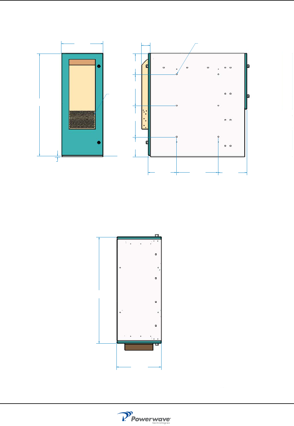
Figure 5-1 Outdoor System Dimensions
16.142
410
FRONT
16.0 in
406.40 mm
38.0 in
964.64 mm
TOP VIEW
DOORS CLOSED
FRONT
REAR
5
4
(16 in)
406.41 mm
(39.25 in)
996.95 mm
(.50 in)
12.70mm
INTAKE LOUVERS
FRONT
(15.978 in)
405.85 mm
(11.0 in)
279.40 mm
(7.555 in)
191.90 mm
(12.0 in)
304.80mm
(12.0 in)
304.80 mm
(8.063 in)
204.80 mm
(11.0 in)
279.40 mm
(3.311 in)
84.10 mm
SIDE
6X M10X1.5
20.8MM MIN THREAD DEPTH
SAME PATTERN BOTH SIDES
Introduction OS-1933-E3-003
044-05243 Rev A 5-5
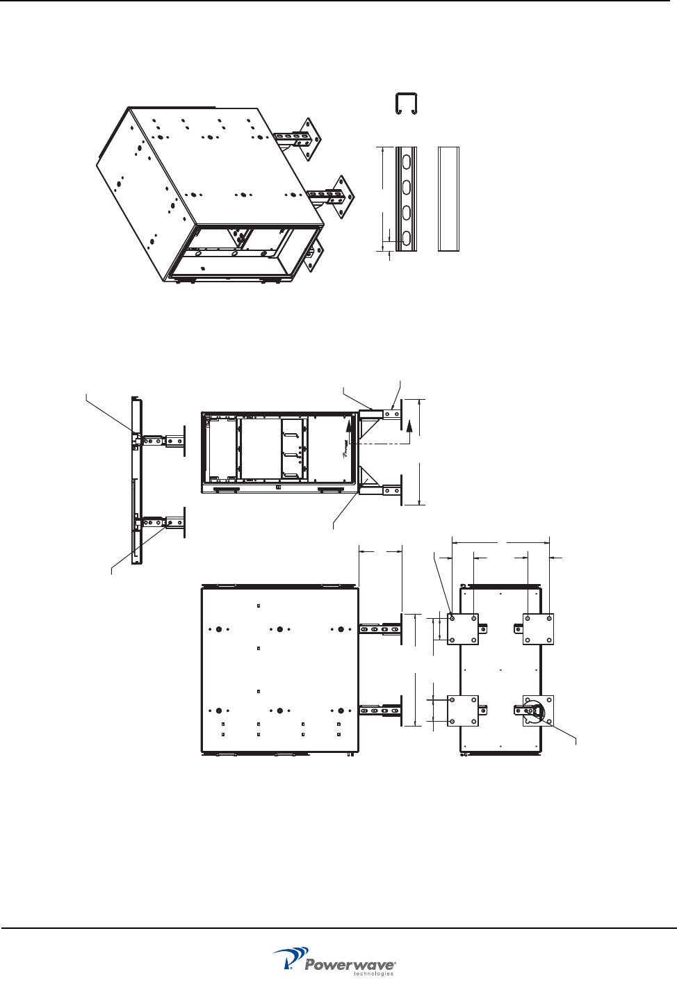
Figure 5-2 Installation Example One
LIST OF MATERIAL
20.813
DETAIL 1 (CHANNEL)
CUT TO LENGTH
UNISTRUT P1000T
UNISTRUT
POST BASE P2072ASQ
UNISTRUT
ANGLE FITTING
P2484W
8.500
22.000
4.250
19.063
16.000 4.250
4.250
4.250
Ø .750
SECURE P2484 TO
BOTTOM OF OS WITH
M12-24 BOLT WITH LOCK
AND FLAT WASHER.
P1000T 8.18 LG CHANNEL QTY 4
P2072ASQ POST BASE QTY 4
P2484W ANGLE QTY 4
P3010 NUT QTY 16
BOLT 1/2 x 1 1/2 QTY 16
M12-24 BOLT QTY 4
M12 FLAT AND LK WASHER QTY 4
DETAIL 1 (CHANNEL)
UNISTRUT P1000T
8.188
.720
SECTION B-B
SCALE 1 : 10
SECURE P2484 ANGLE
TO CHANNEL USING UNISTRUT
HARDWARE: NUT P3010, BOLT HEX 1/2 x 1 -1/2
2 REQD PER ANGLE.
SECURE P2072ASQ POST BASE
TO CHANNEL USING UNISTRUT
HARDWARE: NUT P3010, BOLT HEX 1/2 x 1 1/2
2 REQD PER BASE
B
B
OS-1933-E3-003 Introduction
5-6 044-05243 Rev A
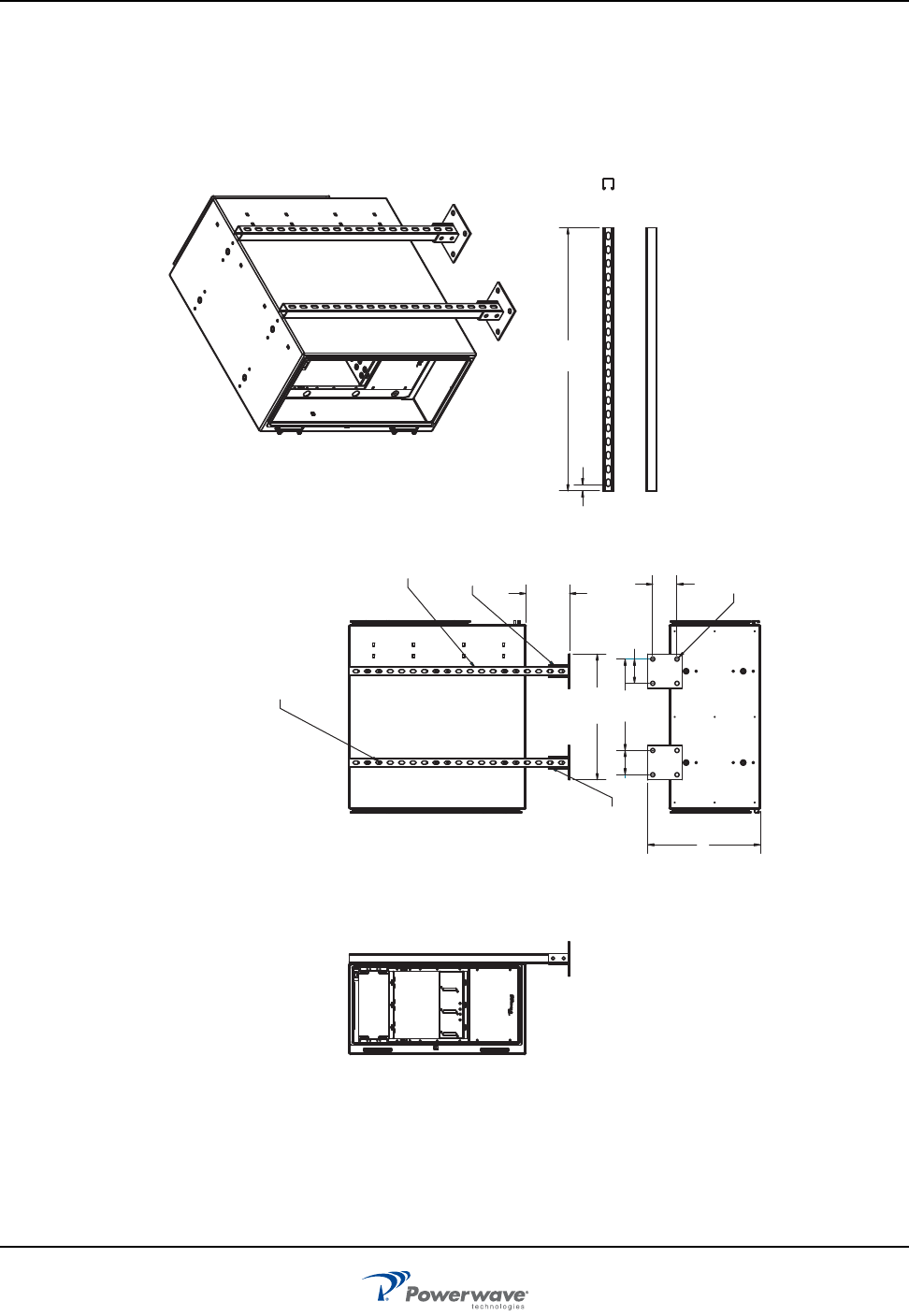
Figure 5-3 Installation Example Two
P1000T 38.38 LG CHANNEL QTY 4
P2072ASQ POST BASE QTY 2
P3010 NUT QTY 4
BOLT 1/2 x 1 1/2 QTY 4
M12-70 BOLT QTY 6
M12 FLAT AND LK WASHER QTY 6
7.62
22.000
DETAIL 2 UNISTRUT CUT TO
LENGTH # P1000T
UNISTRUT POST BASE
#P2072ASQ
SECURE P2072ASQ POST BASE
TO CHANNEL USING UNISTRUT
HARDWARE: NUT P3010, NUT HEX
1/2 x 1 1/2. 2 REQD PER BASE
SECURE CHANNEL TO OS SIDE
USING M12-70 HEX BOLT, FLAT AND
LOCK WASHER. 3 REQD PER CHANNEL.
16.00 4.25
4.25
4.25
Ø .750
19.72
DETAIL 2
UNISTRUT P1000T
38.38
.91
LIST OF MATERIAL
Introduction OS-1933-E3-003
044-05243 Rev A 5-7
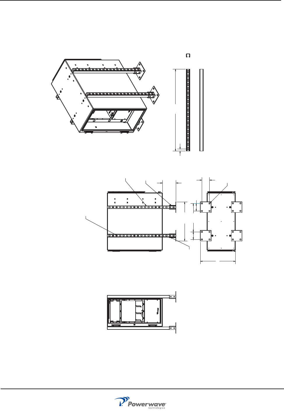
Figure 5-4 Installation Example Three
P1000T 38.38 LG CHANNEL QTY 4
P2072ASQ POST BASE QTY 4
P3010 NUT QTY 8
BOLT 1/2 x 1 1/2 QTY 8
M12-70 BOLT QTY 12
M12 FLAT AND LK WASHER QTY 12
7.62
22.00
DETAIL 2 UNISTRUT CUT TO
LENGTH # P1000T
UNISTRUT POST BASE
#P2072ASQ
SECURE P2072ASQ POST BASE
TO CHANNEL USING UNISTRUT
HARDWARE: NUT P3010, NUT HEX
1/2 x 1 1/2. 2 REQD PER BASE
SECURE CHANNEL TO OS SIDE
USING M12-70 HEX BOLT, FLAT AND
LOCK WASHER. 3 REQD PER CHANNEL.
16.00 4.25
4.25
4.25
Ø .750
19.72
DETAIL 2
UNISTRUT P1000T
38.38
.91
LIST OF MATERIAL