Powerwave Technologies 5JS0120 Nexus Dual Band Repeater User Manual Nexus FT RMR indd
Powerwave Technologies Inc Nexus Dual Band Repeater Nexus FT RMR indd
Users Manual

COVERAGE SOLUTIONS
INSTALLATION AND SERVICE MANUAL
044-05326 REV. B JULY 2010
NEXUS FT RACK MOUNT RADIO

© 2010 Powerwave Technologies Incorporated. All rights reserved.
Powerwave Technologies and the Powerwave logo are registered trademarks.
Powerwave Technologies Inc. reserves the right to make changes to documentation and equipment, including but not limited to com-
ponent substitution and circuitry changes. Changes that impact this document may be subsequently incorporated in a later revision
of this document.
This Powerwave product is designed to operate within the Normal Operating (typical operating) ranges or conditions specified in this
document. Operation of this equipment beyond the specified ranges in this document may cause (1) spurious emissions that violate
regulatory requirements; (2) the equipment to be automatically removed from service when maximum thresholds are exceeded; or
(3) the equipment to not perform in accordance with its specifications. It is the Operator's responsibility to ensure this equipment is
properly installed and operated within Powerwave operating specifications to obtain proper performance from the equipment and to
comply with regulatory requirements.
The rated output power of a Nexus FT is for multiple carriers. As long as the composite power does not exceed the rated power
(20W for North America), derating is not required for multiple carriers. For situations where regulatory requirements require reduced
interference to adjacent band users, the rating would have to be reduced by 3 dB. This power reduction is to be by means of input
power or gain reduction and not by an attenuator at the output of the device. Input power is rated at 115/230VAC, 50/60Hz, and
should be protected based on the power and fuse specifications in Chapter 5 of this manual. Power strips should, at a minimum,
conform to this requirement to prevent equipment damage and possible overload.
Federal Communications Commission (FCC)
This device complies with the technical standards governing mobile radio devices in accordance with FCC Rules. This device is
intended to facilitate the reception and transmission of mobile radio devices in the cellular, PCS or other mobile services, and its
operation by end users or others requires carrier consent under FCC rules. This equipment has been tested and found to comply
with the limits for a Class A digital device, pursuant to CRF47 part 15 of the FCC rules. This equipment is also certified to CRF47 part
22 (cellular), part 24 (PCS) and part 90 (iDEN800 and iDEN900) of the FCC Rules depending on the band of operation. Changes or
modifications not expressly approved by Powerwave Technologies, Inc. for compliance could void the user’s authority to operate this
equipment. These limits are designed to provide reasonable protection against harmful interference when the equipment is operated
in a commercial environment. This equipment generates, uses, and can radiate radio frequency energy and, if not installed and used
in accordance with the instruction manual, may cause harmful interference to radio communications. Operation of this equipment in
a residential area is likely to cause harmful interference in which case the user will be required to correct the interference at his own
expense.
Industry Canada
The measured Canadian RF output power for the RH905022/13B is 46.3dBm.
European Requirements
The Powerwave Nexus FT apparatus introduced in EU markets are certified to ESTI EN 300 609-4 (GSM900 and DCS1800) and
ESTI EN 301 908-11 (WCDMA).
Powerwave Technologies Inc., 1801 East St. Andrew Place, CA 92705 Santa Ana, USA.
Phone +1 714 466 1000 – Fax +1 714 466 5800 – Internet www.powerwave.com

044-05326 Rev B iii
Revision Record
Revision Letter Date of Change Reason for Change
Rev A September 2008 Initial release
Rev B July 2010 Updated manual to show new FT RMR product

Nexus FT RM RMR
iv 044-05326 Rev B
This page intentionally left blank

Nexus FT RM RMR Table of Contents
044-05326 Rev B v
TABLE OF CONTENTS
Warning, Cautions, and Notes . . . . . . . . . . . . . . . . . . . . . . . . . . . . . . . . . . . . . . . . . . . . . . . . . . . . . . . . . . . vii
Safety . . . . . . . . . . . . . . . . . . . . . . . . . . . . . . . . . . . . . . . . . . . . . . . . . . . . . . . . . . . . . . . . . . . . . . . . . . . . . . vii
Human Exposure to RF Radiation . . . . . . . . . . . . . . . . . . . . . . . . . . . . . . . . . . . . . . . . . . . . . . . . . . . . . vii
Repeater Antennas . . . . . . . . . . . . . . . . . . . . . . . . . . . . . . . . . . . . . . . . . . . . . . . . . . . . . . . . . . . . . vii
Installation and Maintenance of Antenna Systems . . . . . . . . . . . . . . . . . . . . . . . . . . . . . . . . . . . . . vii
Radiation Exposure . . . . . . . . . . . . . . . . . . . . . . . . . . . . . . . . . . . . . . . . . . . . . . . . . . . . . . . . . . . . .viii
Electrostatic Discharge (ESD) . . . . . . . . . . . . . . . . . . . . . . . . . . . . . . . . . . . . . . . . . . . . . . . . . . . . . . . . . . . viii
Chapter 1 - Product Description
Introduction . . . . . . . . . . . . . . . . . . . . . . . . . . . . . . . . . . . . . . . . . . . . . . . . . . . . . . . . . . . . . . . . . . . . . . . . . 1-1
Scope of Manual . . . . . . . . . . . . . . . . . . . . . . . . . . . . . . . . . . . . . . . . . . . . . . . . . . . . . . . . . . . . . . . . . . . . . 1-1
Overview . . . . . . . . . . . . . . . . . . . . . . . . . . . . . . . . . . . . . . . . . . . . . . . . . . . . . . . . . . . . . . . . . . . . . . . . . . . 1-1
Cabinet Design . . . . . . . . . . . . . . . . . . . . . . . . . . . . . . . . . . . . . . . . . . . . . . . . . . . . . . . . . . . . . . . . . . . 1-2
Rack Mount Radio module (RMR) . . . . . . . . . . . . . . . . . . . . . . . . . . . . . . . . . . . . . . . . . . . . . . . . . . . . . . . 1-2
Chapter 2 - Indicators
Introduction . . . . . . . . . . . . . . . . . . . . . . . . . . . . . . . . . . . . . . . . . . . . . . . . . . . . . . . . . . . . . . . . . . . . . . . . . 2-1
Indicators . . . . . . . . . . . . . . . . . . . . . . . . . . . . . . . . . . . . . . . . . . . . . . . . . . . . . . . . . . . . . . . . . . . . . . . . . . 2-1
Chapter 3 - Installation
Introduction . . . . . . . . . . . . . . . . . . . . . . . . . . . . . . . . . . . . . . . . . . . . . . . . . . . . . . . . . . . . . . . . . . . . . . . . . 3-1
Site Survey . . . . . . . . . . . . . . . . . . . . . . . . . . . . . . . . . . . . . . . . . . . . . . . . . . . . . . . . . . . . . . . . . . . . . . . . . 3-1
Unpacking and Inspection . . . . . . . . . . . . . . . . . . . . . . . . . . . . . . . . . . . . . . . . . . . . . . . . . . . . . . . . . . . . . 3-1
RMR Cabinet Location . . . . . . . . . . . . . . . . . . . . . . . . . . . . . . . . . . . . . . . . . . . . . . . . . . . . . . . . . . . . . . . . 3-1
Rack Mounting the RMR . . . . . . . . . . . . . . . . . . . . . . . . . . . . . . . . . . . . . . . . . . . . . . . . . . . . . . . . . . . 3-1
Connections . . . . . . . . . . . . . . . . . . . . . . . . . . . . . . . . . . . . . . . . . . . . . . . . . . . . . . . . . . . . . . . . . . . . . . . . 3-2
Downlink and Uplink . . . . . . . . . . . . . . . . . . . . . . . . . . . . . . . . . . . . . . . . . . . . . . . . . . . . . . . . . . . . . . . 3-2
Service and WLI . . . . . . . . . . . . . . . . . . . . . . . . . . . . . . . . . . . . . . . . . . . . . . . . . . . . . . . . . . . . . . . . . . 3-3
Main Power and Grounding . . . . . . . . . . . . . . . . . . . . . . . . . . . . . . . . . . . . . . . . . . . . . . . . . . . . . . . . . 3-4
Commissioning . . . . . . . . . . . . . . . . . . . . . . . . . . . . . . . . . . . . . . . . . . . . . . . . . . . . . . . . . . . . . . . . . . . . . . 3-5
Initial Startup . . . . . . . . . . . . . . . . . . . . . . . . . . . . . . . . . . . . . . . . . . . . . . . . . . . . . . . . . . . . . . . . . . . . 3-5
Chapter 4 - Maintenance
Introduction . . . . . . . . . . . . . . . . . . . . . . . . . . . . . . . . . . . . . . . . . . . . . . . . . . . . . . . . . . . . . . . . . . . . . . . . . 4-1
Periodic Maintenance . . . . . . . . . . . . . . . . . . . . . . . . . . . . . . . . . . . . . . . . . . . . . . . . . . . . . . . . . . . . . . . . . 4-1
Troubleshooting . . . . . . . . . . . . . . . . . . . . . . . . . . . . . . . . . . . . . . . . . . . . . . . . . . . . . . . . . . . . . . . . . . . . . 4-1
Clearing Alarm Faults . . . . . . . . . . . . . . . . . . . . . . . . . . . . . . . . . . . . . . . . . . . . . . . . . . . . . . . . . . . . . . 4-1
Field Replaceable Units . . . . . . . . . . . . . . . . . . . . . . . . . . . . . . . . . . . . . . . . . . . . . . . . . . . . . . . . . . . . . . . 4-5
Fan Removal and Replacement . . . . . . . . . . . . . . . . . . . . . . . . . . . . . . . . . . . . . . . . . . . . . . . . . . . . . . 4-5
NetWay Manager (NWM) . . . . . . . . . . . . . . . . . . . . . . . . . . . . . . . . . . . . . . . . . . . . . . . . . . . . . . . . . . . . . . 4-6
Return For Service Procedures . . . . . . . . . . . . . . . . . . . . . . . . . . . . . . . . . . . . . . . . . . . . . . . . . . . . . . . . . 4-6
Obtaining an RMA . . . . . . . . . . . . . . . . . . . . . . . . . . . . . . . . . . . . . . . . . . . . . . . . . . . . . . . . . . . . . . . . 4-6
Repackaging for Shipment . . . . . . . . . . . . . . . . . . . . . . . . . . . . . . . . . . . . . . . . . . . . . . . . . . . . . . . . . . 4-6
Chapter 5 - Specifications
Introduction . . . . . . . . . . . . . . . . . . . . . . . . . . . . . . . . . . . . . . . . . . . . . . . . . . . . . . . . . . . . . . . . . . . . . . . . . 5-1

Table of Contents Nexus FT RM RMR
vi 044-05326 Rev B
List of Figures
1-1 Powerwave Nexus FT RM rack- fully equipped . . . . . . . . . . . . . . . . . . . . . . . . . . . . . . . . . . . . . . . . .1-2
1-2 Nexus FT Rack Mount Radio (RMR) . . . . . . . . . . . . . . . . . . . . . . . . . . . . . . . . . . . . . . . . . . . . . . . . . 1-2
2-1 External Indicators . . . . . . . . . . . . . . . . . . . . . . . . . . . . . . . . . . . . . . . . . . . . . . . . . . . . . . . . . . . . . . . 2-1
3-1 Downlink and Uplink Connections . . . . . . . . . . . . . . . . . . . . . . . . . . . . . . . . . . . . . . . . . . . . . . . . . . . 3-2
3-2 RMR Service and WLI Connections . . . . . . . . . . . . . . . . . . . . . . . . . . . . . . . . . . . . . . . . . . . . . . . . . . 3-3
3-3 RMR Main Power and Grounding Connections . . . . . . . . . . . . . . . . . . . . . . . . . . . . . . . . . . . . . . . . . 3-4
4-1 Fan Assembly Screws . . . . . . . . . . . . . . . . . . . . . . . . . . . . . . . . . . . . . . . . . . . . . . . . . . . . . . . . . . . . 4-5
4-2 Fan Assembly . . . . . . . . . . . . . . . . . . . . . . . . . . . . . . . . . . . . . . . . . . . . . . . . . . . . . . . . . . . . . . . . . . . 4-5
List of Tables
3-1 Downlink and Uplink Connection Procedure . . . . . . . . . . . . . . . . . . . . . . . . . . . . . . . . . . . . . . . . . . . . 3-2
3-2 RMR Service and WLI Connections . . . . . . . . . . . . . . . . . . . . . . . . . . . . . . . . . . . . . . . . . . . . . . . . . . 3-3
3-3 RMR Main Power and Grounding . . . . . . . . . . . . . . . . . . . . . . . . . . . . . . . . . . . . . . . . . . . . . . . . . . . . 3-4
3-4 Initial Status Procedure . . . . . . . . . . . . . . . . . . . . . . . . . . . . . . . . . . . . . . . . . . . . . . . . . . . . . . . . . . . . 3-5
4-1 Recommended Periodic Maintenance . . . . . . . . . . . . . . . . . . . . . . . . . . . . . . . . . . . . . . . . . . . . . . . . 4-1
4-2 Alarm Troubleshooting . . . . . . . . . . . . . . . . . . . . . . . . . . . . . . . . . . . . . . . . . . . . . . . . . . . . . . . . . . . . 4-1
4-3 Fan Removal . . . . . . . . . . . . . . . . . . . . . . . . . . . . . . . . . . . . . . . . . . . . . . . . . . . . . . . . . . . . . . . . . . . . 4-5
5-1 RMR Specifications . . . . . . . . . . . . . . . . . . . . . . . . . . . . . . . . . . . . . . . . . . . . . . . . . . . . . . . . . . . . . . . 5-1
044-05326 Rev B vii
Preface
Warning, Cautions, and Notes
Warnings, Cautions, and Notes are found throughout this manual where applicable. The associated icons in
warnings and cautions are used to quickly identify a potential condition that could result in the consequences
described below if precautions are not taken. Notes clarify and provide additional information to assist the
user.
WARNING: The warning symbol means danger. You are in a situation that could cause bodily
injury or death. Before you work on any equipment, be aware of the hazards involved with elec-
trical and RF circuitry and be familiar with standard practices for preventing accidents.
CAUTION: The caution symbol means the potential exists for equipment damage or loss of
data.
NOTE: Notes contain helpful suggestions or references to material not covered in the document.
Safety
Any personnel involved in installation, operation, or service of units included in a Powerwave repeater
system must understand and follow the points below:
❑Powerwave Nexus FT Rack Mount Radios (RMR) are designed to receive and amplify signals from
one or more base stations and retransmit the signals to one or more mobile stations. They also act
the other way round, that is to receive signals from one or more mobile stations, then amplify and
retransmit the signals to the base stations. Powerwave Nexus FT RMR systems must be used
exclusively for this purpose and nothing else.
❑Units supplied from the mains must be connected to grounded outlets and in conformity with the local
prescriptions.
❑Power supply units supplied from the mains contain dangerous voltage that can cause electric shock.
Disconnect the mains prior to any work in such a unit. Local regulations are to be followed when
servicing such units. Only authorized service personnel are allowed to service units while the mains
are connected.
❑All RF transmitting units, including Nexus FT RMRs, will generate radio signals and thereby give rise
to electromagnetic fields that may be hazardous to the health of any person who is extensively
exposed close to an antenna.
Human Exposure to RF Radiation
Safe distances must be kept when working around antennas. The following paragraphs describe the
cautions to be aware of during the installation and maintenance of antenna systems and how to calculate
safety distances needed for RF radiation at different antenna power and frequencies.
Repeater Antennas
To be able to receive and transmit signals, a repeater is connected to a donor antenna directed towards the
base station and a service antenna directed towards the coverage area. A fiber optic cable from the base
station might, however, be substituted for the donor antenna.
Installation and Maintenance of Antenna Systems
Installation and maintenance of all antenna systems must be performed with respect to the radiation
exposure limits for public areas. The antenna radiation level is affected by the output power, antenna gain,
and transmission devices such as cables, connectors, splitters and feeders. Also have in mind the system
minimum coupling loss, typically between 25 dB and 35 dB, is determined by a standard with the purpose
to protect base stations from noise and other performance dropping effects.

Electrostatic Discharge (ESD) Nexus FT RM RMR
viii 044-05326 Rev B
Radiation Exposure
The World Health Organization (WHO) and International Commission on Non-Ionising Radiation Protection
(ICNIRP) have determined recommendations for radiation exposure. ICNIRP recommends not to exceed
the following radiation power for public exposure:
Frequency Radiation power
800/900 MHz 4.5W/m²
1800/1900 MHz 9.0W/m²
2100 MHz 10.0W/m²
For antennas larger than 20cm the maximum radiation power can be calculated by using the following
formula:
Electrostatic Discharge (ESD)
ESD can severly damage essential parts of the equipment if not handled carefully. Parts on
Printed Circuit Board Assemblies (PCBA) as well as other parts in the equipment are
sensitive to ESD. Never touch the PCBA or uninsulated conductor surfaces unless
absolutely necessary.
If you must handle the PCBAs or uninsulated conductor surfaces, use ESD protective
equipment or first touch the chassis with your hand. Never let your clothes touch PCBAs or
uninsulated conductor surfaces and always store PCBAs in ESD-safe bags.
S= P/(4πr2)
S = Radiation power in W/m²
P = Output power in W
r = Distance between antenna and human in meters

044-05326 Rev B 1-1
Chapter 1
Product Description
Introduction
This manual contains information and procedures for installation, operation, and maintenance of the Rack
Mount Radio module as part of the Nexus FT Rack Mount Repeater. In this manual, the Nexus FT Rack Mount
Radio is referred to as the RMR. The manual is organized into chapters as follows:
Scope of Manual
This manual is intended for use by service technicians familiar with similar types of equipment. It contains
required service information for the RMR and is current as of the printing date. Changes which occur after the
printing date may be incorporated by a complete manual revision or alternatively as additions.
Overview
The RMR is a repeater designed to be part of a Distributed Antenna System (DAS). The components are
mounted on a 19 in. rack and are intended for use in an indoor, temperature controlled environment.
As part of a DAS, the RMR extends coverage into uncovered areas in wireless mobile systems such as base
station fringe areas, tunnels, convention centers, airports, and buildings. It receives, amplifies, and transmits
signals to/from a Base Transceiver Station (BTS) and to/from Mobile Stations (MS).
The RMR unit is a dual wide band, bi-directional, RF amplifier with two separate donor ports and a common
(duplexed) service port per band. It connects to aFiber Base Distribution Unit (FBU) that combines, splits and
converts RF signals to an optical signal in the Uplink (UL) direction. In the Downlink (DL) direction, the FBU
converts optical signals to RF signals and splits the signal to RF outputs. Two separate full-duplex fibers handle
signal transport between the BTS Master Unit and the FBU. See the Fiber Base Unit Installation and Service
Manual (part number 044-05348) for more details. The DL signal and the UL signal combine onto one optical
fiber through a Wavelength Division Multiplexer (WDM). Wideband 4-way combiners handle RF splitting and
combining. The UL output signal is connected to the FBU via RF coax cable, converted to light, and sent via
fiber toward the BTS.
A Wireless Portal module distributes the DL/UL signals to/from the DAS.
The RMR is microprocessor controlled with alarm and operational status LEDs visible on the front. Cooling is
provided through forced air fans. Operational parameters are set using a PC running Powerwave OM-Online
software which communicates with the RMRs through the FBU or through a system solution. Remote operation
can be accomplished via Public Switched Telephone Network (PSTN) or a GSM net. The Operation and
Maintenance System (OMS) provides for Network Operations Center (NOC) configuration and alarm
monitoring.
❑Chapter 1- Product Description
❑Chapter 2- Indicators
❑Chapter 3- Installation
❑Chapter 4- Maintenance
❑Chapter 5- Specifications
Rack Mount Radio module (RMR) Nexus FT RMR
1-2 044-05326 Rev B
Cabinet Design
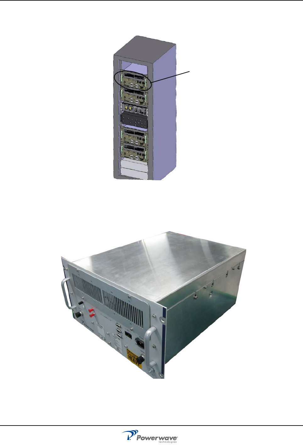
The Nexus FT RMR modules are intended to be mounted in a 482 mm (19 in) cabinet at least 600 mm (23 in)
deep, similar to the one shown Figure 1-1.I
Figure 1-1 Powerwave Nexus FT RM rack- fully equipped
Rack Mount Radio module (RMR)
RMRs can handle multiple carriers over a wide band. The cabinet can be equipped with up to four RMRs.
Figure 1-2 Nexus FT Rack Mount Radio (RMR)
Typical RMR position
044-05326 Rev B 2-1
Chapter 2
Indicators
Introduction
This chapter contains descriptions of the controls, indicators, and connectors for the Nexus FT RMR.
Indicators
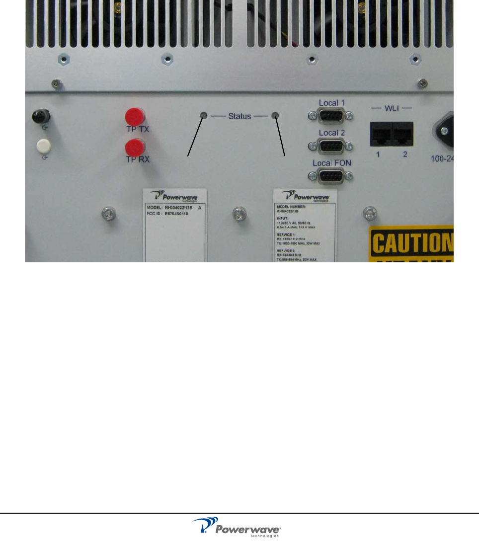
Figure 2-1 External Indicators
The LEDs, shown in Figure 2-1, provide easy identification of a fault in the system. The amber operation LED
lights up approximately 15 seconds after the main power is switched on. When the LED is steady, the RMR is
ready for operation. The red alarm LED indicates a system error alarm when flashing and a critical alarm
when steady.
Red Amber

Indicators Nexus FT RMR
2-2 044-05326 Rev B
This page intentionally left blank

044-05326 Rev B 3-1
Chapter 3
Installation
Introduction
This chapter contains unpacking, inspection, and installation instructions for installing and powering up the
Nexus FT RMR.
Site Survey
Powerwave recommends that a site survey be performed prior to equipment ordering or installation.
Performing a detailed site survey reduces or eliminates installation and turn-up delays. Pay particular
attention to power plant capacity, cooling needs, floor space, and RF/DC cabling/breaker requirements.
Cabinet dimensions and weights are listed in Chapter 5.
Unpacking and Inspection
This equipment has been operated, tested, and calibrated at the factory. Carefully open the container to
remove the equipment. Retain all packing material so it can be reassembled in the event the unit must be
returned to the factory. Perform the following steps:
❑ Visually inspect equipment for damage that may have occurred during shipment. If possible, in the
presence of the delivery person, if possible.
❑ Check for evidence of water damage, bent or warped chassis, loose screws or nuts, or extraneous
packing material in connectors.
If the equipment is damaged, file a claim with the carrier once the extent of the damage is assessed.
If the equipment must be returned to the factory, please contact the factory for a Return Material Authorization
(RMA). See Chapter 4.
RMR Cabinet Location
The RMR is designed for use in an indoor, temperature controlled environment mounted in a 19 inch cabinet.
Ensure the rear of the unit is supported properly.The RMR should be placed in an area that is free of
obstructions, easily accessible, and allows for proper air-flow and ventilation.
Rack Mounting the RMR
1. Set the RMR in the required position.
2. Align the mounting holes with the holes on the rack.
3. Insert the four mounting screws and tighten until secure.
4. Ensure the rear of the unit is supported properly.
Connections Nexus FT RMR
3-2 044-05326 Rev B
Connections
Downlink and Uplink
RF and fiber cable connections should be verified both internally and externally before powering up the
equipment. Verify these connections with the as-built drawings and documents for your specific system
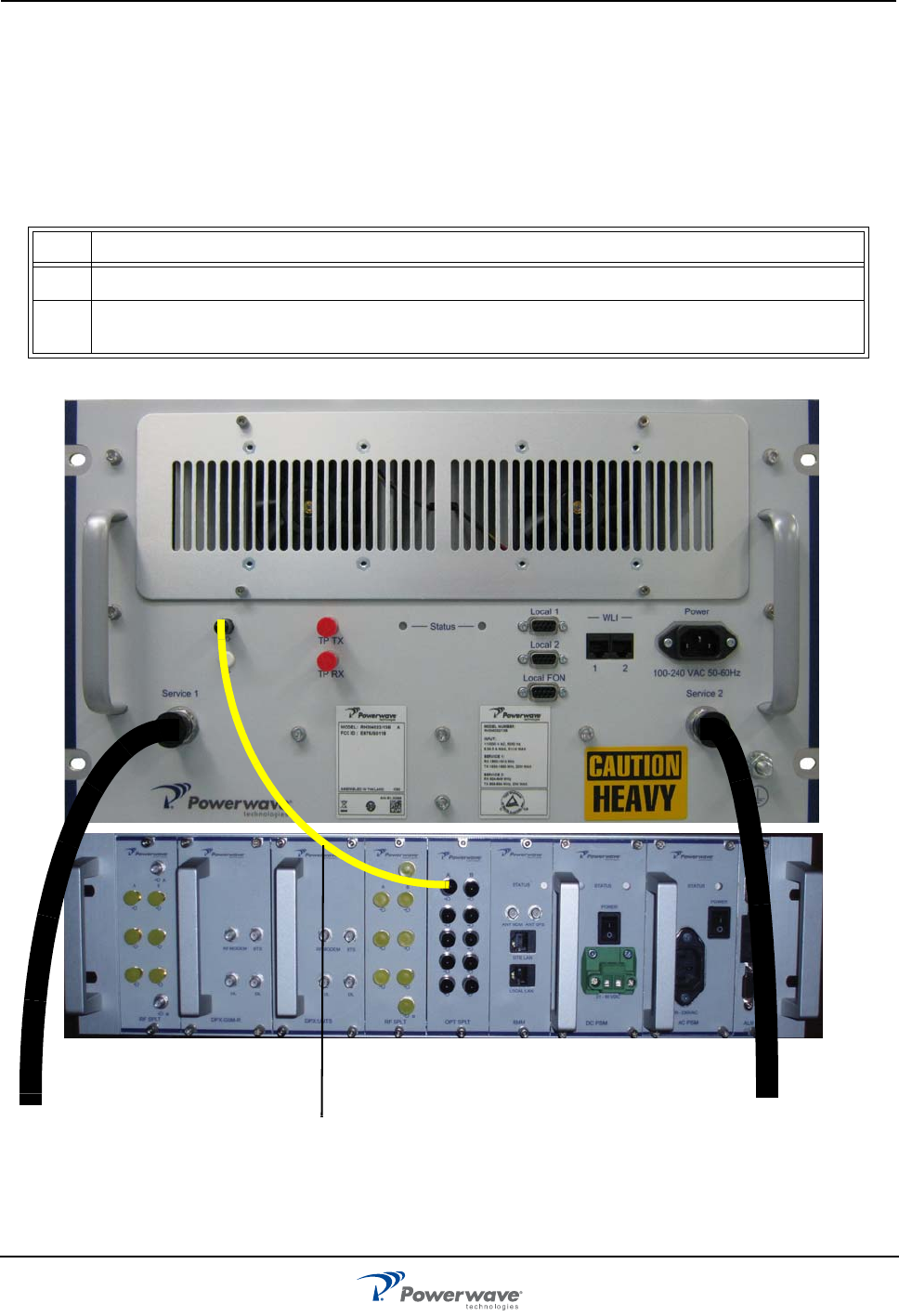
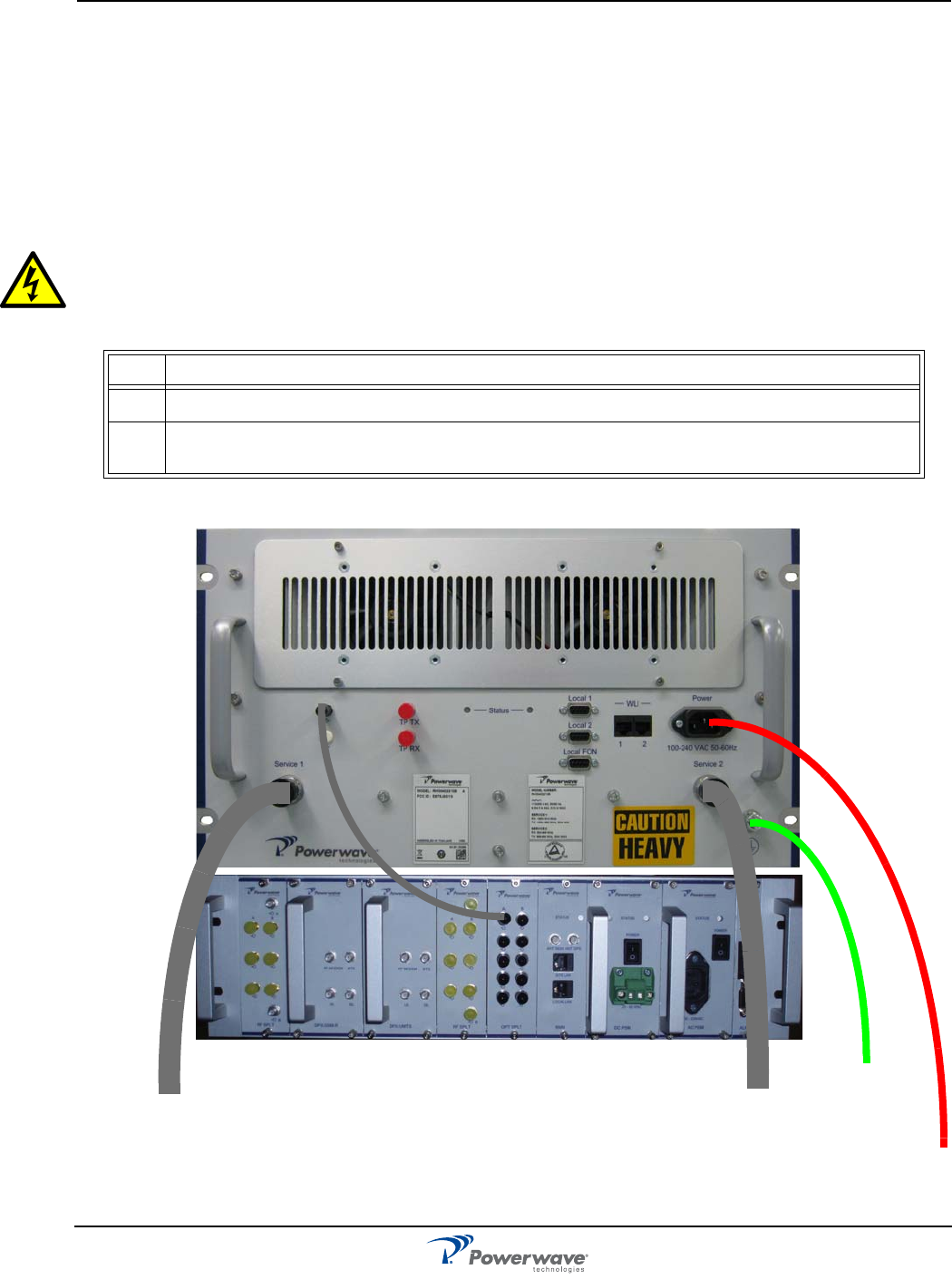
configuration. Table 3-1 and Figure 3-1 show the steps to connect the RMR module to the Nexus Fiber Base
Unit (FBU) at the head end.
Table 3-1 Connection Procedure
Figure 3-1 RMR to FBU and Service 1/2 Connections
Step Action
1 Connect a fiber cable between the RMR fiber terminal and a head end device, such as the FBU.
2 Connect an RF cable between the customer’s system and the Service 1 and Service 2 ports on the
RMR.
Fiber cable
Service 2
Service 1
Nexus FT RMR Connections
044-05326 Rev B 3-3
Main Power and Grounding
Local regulations need to be followed for the main power connection. Nexus FT RMRs are approved in
accordance with EN and UL/cUL regulations. This is, however, only valid if a classified power cord is used.
For the Nexus FT RMR to meet these regulations you must select one of the following classified and
approved cord types:
❑ EN – H 05 W5 - F HMR
❑ UL – AWM Style 2587
❑ CSA– AWM 1 A/B 11 A/B
WARNING: For Nexus FT RMRs supplied from the main power source, the main outlet must be
grounded.
Table 3-2 RMR Main Power and Grounding
Figure 3-2 RMR Main Power and Grounding Connections
Step Action
1 Connect a power cable between the RMR and an appropriate power supply.
2 Connect a ground cable between the ground terminal on the RMR and an appropriate ground at the
installation site.
Power cable
Ground Cable

Commissioning Nexus FT RMR
3-4 044-05326 Rev B
Commissioning
Before proceeding, carefully read the Safety section and check all connections made during the installation.
Ensure cables are properly tightened and not damaged.
The RMR can be configured locally with OM-Online by connecting a standard serial cable from the COM port
on the PC to the P31 PC port (RS-232) located on the front of the RMR. Details on using OM-Online are
described in the OM-Online User Manual - Connecting a PC for Local Access
Initial Startup
To complete the initial start-up of the Nexus FT RMR, follow the steps listed in Table 3-4.
Table 3-3 Initial Statup Procedure
NOTE: When optimizing RMRs, offset the UL gain 20 dB less than the DL gain as a starting point.
Always monitor the UL pass bands for noise levels and/or IMDs when optimizing and commission-
ing.
Step Action
1 Turn main power on.
2 Check the LEDs on the RMR. Refer to Figure 2-1 in Chapter 2 for correct power up indications.

044-05326 Rev B 4-1
Chapter 4
Maintenance
Introduction
This chapter contains periodic maintenance and performance test procedures for the Nexus FT RMR.
Periodic Maintenance
Periodic maintenance requirements are listed in Table 4-1, as well as the intervals at which the tasks should
be performed.
Troubleshooting
The sections that follow contain a list of problems that could occur and a few suggested actions that might
correct each problem. If the suggested corrective action does not eliminate the problem, please contact your
Powerwave field representative or help line for further instruction.
Clearing Alarm Faults
Table 4-2 lists the alarms that can be generated in the Nexus FT RMR. Critical, Error, and Warning alarms are
sent automatically from a Nexus FT RMR to OM-Online, stored and then viewed in the Alarm window.
Table 4-1 Recommended Periodic Maintenance
Task Interval Action
Inspection of cables
and connectors
12 months Inspect power, RF, and Fiber cables for signs of damage or wear
(frayed insulation, cracks, punctures, etc.) Check connections to be
sure they are tight.
Clean cooling fans 12 months Clean any dirt or debris that may potentially block air flow.
Optional Perform cable sweeps.
Clean equipment Clean as required depending on operating environment.
Table 4-2 Alarm Troubleshooting
ID Alarm Text Alarm Unit Alarm Description
1 Power PSM Critical PSM does not work properly. A sum signal from the PSM
indicates that at least one voltage output has dropped. If no mains
breakdown relay is used, then the alarm will also be sent at mains
breakdown
Ceasing PSM. Ceasing is sent if the PSM works at start-up, and there is a
corresponding critical PSM alarm logged in the Events log. The
RMR will restart when the power is back and this alarm will be
sent
Ceasing The cause of the alarm has ceased

Troubleshooting Nexus FT RMR
4-2 044-05326 Rev B
2 RMR restart CU None Power on start, or user ordered reboot. Logged to indicate a
normal power up, or a restart ordered by the operator
Warning Software error restart, 1st – 7th time. Restart 1st to 7th time during
a 14 day period. The counter is reset every 14th day, counted
from power up
Error Software error restart 8th – 10th time. Restart 8th to 10th time
during the 14 day period. At the 11th time, the SW bank will be
blocked and not used anymore until a user ordered reset is
performed, or power is switched off/on
3Mains
breakdown
External Critical The mains power is gone. Used with an external relay indicating
mains breakdown. The external relay should be connected to
External Alarm 1 and the RMR configured to indicate this alarm. If
no relay is used, a mains breakdown will be reported as a PSM
fault
Ceasing The mains power is back. Sent if there is a corresponding critical
mains breakdown alarm logged in the Events Log. The RMR will
restart when the power is back
4 Alarm reset CU None Alarm reset by the user. All alarms are reset. The cause of the
alarm will be re-evaluated and reported, if still active
5 Local bus
error
WBA #,
MCPA#
Error Error when communicating on the bus. The CU has no contact
with the WBA, or MCPA PCBA, which is taken out of service
6 Main bkd w
backup
External Error Used to indicate that the mains is no longer available. RMR is
powered by external battery backup unit. Suggested remedy:
Check the mains power
Ceasing The cause of the alarm has ceased
7Err in AD-
converter
Warning The analog-to-digital converter on the CU PCBA does not give
reliable values
8 New unit
detected
None Compared to the last power on, the CU has recognized at least
one additional hardware unit
9 Inst. unit lost Error Compared to the last power on, the CU lacks at least one
hardware unit
10 EEPROM
error
CU Error EEP read or write fail. Data cannot be written or read from the
EEPROM on the CU PCBA. User parameters are stored in the
EEPROM
11 Log memory
fault
Error Log memory fault. Indicates that the log memory on the CU PCBA
is faulty. The RMR will not work. Not available in all CU software
versions
12 High temp CU Warning The CU PCBA temperature is higher than 90°C
Ceasing The CU PCBA temperature has fallen below 90°C
13 REFO error Error Significant REFO drift or error detected by CU
14 Ext REFO
error
Warning Suggested remedy: Check the reference source and the cables
Table 4-2 Alarm Troubleshooting (Continued)
ID Alarm Text Alarm Unit Alarm Description

Nexus FT RMR Troubleshooting
044-05326 Rev B 4-3
15 CU battery
fault
CU Warning CU RAM battery fault. The battery for the RAM on the CU PCBA
has a voltage outside the normal 2.7 to 3.5 Volt. An alarm may be
initiated at start-up if the RMR has been stored out of power for a
long time. Suggested remedy: Ensure jumper P3 on the CU PCBA
is mounted to charge the battery
Ceasing The cause of the alarm has ceased
16 SW load error CU Error Software load error. An error has occurred during a software load
process. The flash memory does not contain a proper software.
Suggested remedy: Check the CU software using the OM-Online
SW Manager. Do NOT restart the RMR
17 Log cleared CU None Log memory has been cleared. The check sum in the Events Log
memory is faulty. The log is cleared. Can be caused by a bad
RAM battery backup or low voltage to the RAM
18 RTC restarted CU None The time is changed by the operator (logged to keep track of
changes made to the RTC)
Warning Time reset to 1994-01-01. The RTC was unable to keep track of
the time and did a reset. Suggested remedy: Ensure jumper P3 on
the CU PCBA is mounted to charge the battery
19 RTC error Error RTC does not operate. The CU has detected an error in the RTC
operation which makes the time unreliable. Suggested remedy:
Replace the CU PCBA
20 Door open
alarm
External Config The door has been open 30 seconds without disabling the alarm
Ceasing The door has been closed 30 seconds, or the alarm is disabled
21 External
alarm 1
External Config External alarm input EA1 active more than 1 second
Ceasing External alarm input EA1 no longer active
22 External
alarm 2
External Config External alarm input EA2 active more than 1 second
Ceasing External alarm input EA2 no longer active
23 Fan failure
alarm 3
External Config External alarm input EA3 active more than 1 second
Ceasing External alarm input EA3 no longer active
24 Fan failure
alarm 4
External Config External alarm input EA4 active more than 1 second
Ceasing External alarm input EA4 no longer active
34 Login failed None Invalid RMR password
40 Battery fault RCU, FON
charger
Error The backup battery on the RCU or the FON PCBA does not work
properly. Suggested remedy: Check cables or replace battery
Ceasing The cause of the alarm has ceased
Table 4-2 Alarm Troubleshooting (Continued)
ID Alarm Text Alarm Unit Alarm Description

Troubleshooting Nexus FT RMR
4-4 044-05326 Rev B
42 Antenna
isolation
WBA #,
Channel #,
UL/DL
Warning Low antenna isolation. The antenna isolation is lower than the
gain set. Gain is reduced by 10dB – 13dB below the oscillation
point. Suggested remedy: Decrease gain or increase antenna
isolation
Error Low antenna isolation at lowest gain. The gain has been reduced
as much as possible but the oscillation still remains. The amplifier
is turned off. Suggested remedy: Decrease gain or increase
antenna isolation
Ceasing Normal operation again, that is no oscillation can be detected
13dB above the gain set
48 Battery
backup fault
External Error If a battery backup unit alarm is connected to external alarm 2,
then the operator can configure the RMR to display this alarm
when the battery backup unit indicates alarm
Ceasing The cause of the alarm has ceased
70 Bad table
alarm
CU Error Requested table contains incorrect information (SW error)
71 Table not
found
CU Error Requested table not found in the database (SW or calibration
error)
72 Table
database
error
CU Error Table database not found (calibration error)
80 Antenna
SWR alarm
Donor
antenna
service
antenna
Error Too low antenna return loss, caused either by cables, connectors,
or antenna problems.
Suggested remedy: Check antenna and cables
Ceasing The cause of the alarm has ceased
90 FON power
alarm
FON RF Error A DC voltage on a FON PCBA is out of range. Suggested remedy:
Replace the FON PCBA.
Ceasing The cause of the alarm has ceased
245 Not In
Allowed Area
CU None RMR is moved from the operating area and the RF HW is
switched on or off
Table 4-2 Alarm Troubleshooting (Continued)
ID Alarm Text Alarm Unit Alarm Description
Nexus FT RMR Field Replaceable Units
044-05326 Rev B 4-5
Field Replaceable Units
The fan assembly is the only field replaceable unit. If any other components fail, please contact Powerwave
for service.
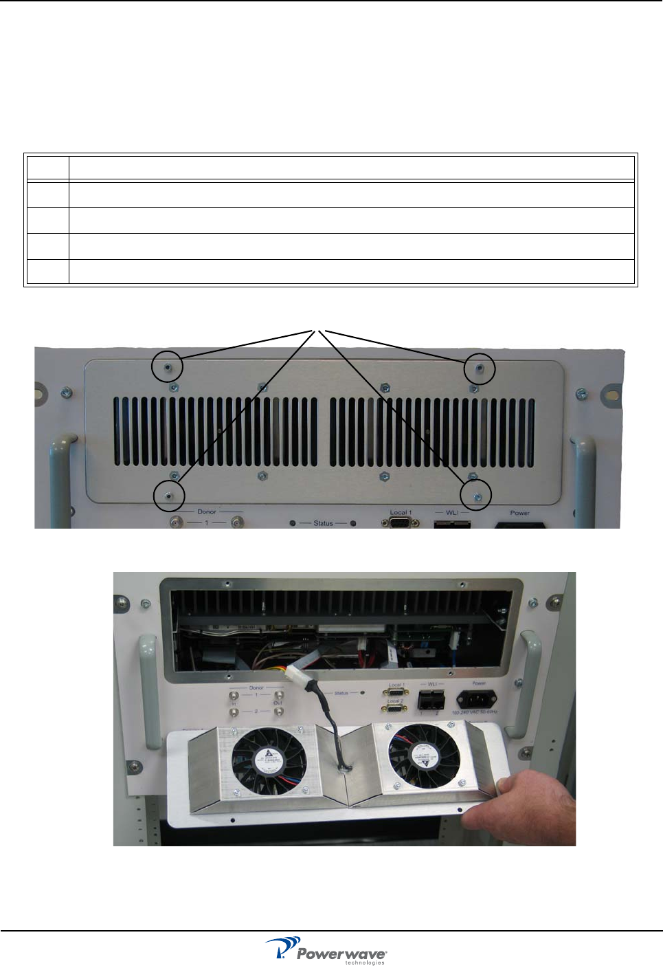
Fan Removal and Replacement
Refer to Table 4-3 and figures 4-1 and 4-2.
Figure 4-1 Fan Assembly Screws
Figure 4-2 Fan Assembly
Table 4-3 Fan Removal
Step Action
1 Disconnect power from the RMR.
2 Remove four retaining screws from the fan assembly housing. See Figure 4-1.
3 Remove the fan assembly and disconnect the plug. See Figure 4-2.
4 Install the new fan assembly in reverse order.
Remove these screws

NetWay Manager (NWM) Nexus FT RMR
4-6 044-05326 Rev B
NetWay Manager (NWM)
NWM is a Powerwave software package for network management. NWM can be used to access repeaters for
alarm reception, radio parameter configuration, software downloading, and scheduling activities.
Return For Service Procedures
When returning products to Powerwave, the following procedures will ensure optimum response.
Obtaining an RMA
A Return Material Authorization (RMA) number must be obtained prior to returning equipment to the factory
for service. Pease contact our Repair Department at +1-714-466-1000 to obtain this number, or FAX your
request to +1-714-466-5800. Failure to obtain this RMA number may result in delays in receiving repair
service.
Repackaging for Shipment
To ensure safe shipment of the unit, it is recommended that the original package designed for shipping the
unit be reused. If it is not available, contact Powerwave’s Customer Service Department at 1-800-797-9283,
+1-714-466-100 or by e-mail at support@pwav.com for packing material.

044-05326 Rev B 5-1
Chapter 5
Specifications
Introduction
This chapter provides specifications for the Nexus FT RMR.
Table 5-1: RMR Specifications
Electrical
Frequency band UL 824 to 849 MHz (Cellular)
806 to 824 MHz (800 iDEN)
896 to 902 MHz (900 iDEN)
1850 to 1910 MHz (PCS)
Frequency band DL 869 to 894 MHz (Cellular)
851 to 869 MHz (800 iDEN)
935 to 941 MHz (900 iDEN)
1930 to 1990 MHz (PCS)
Max absolute delay <300 ns
Gain adjustment range (in 1 dB steps) 30 dB
Gain
Uplink
Downlink
Variation
*These are typical values and may vary due
to cable length.
35 to 60 dB typical - Excluding fiber link
45 to 70 dB typical - Excluding fiber link
Typically ± 1.5 dB versus temperature
± 2.0 dB versus DL frequency
± 0.5 dB versus DL output power
± 0.5 dB versus input voltage
± 2.0 dB versus UL frequency
Instantaneous bandwidth 25 MHz (Cellular)
18 MHz (800 iDEN)
5 MHz (900 iDEN)
60 MHz (PCS)
45 MHz (AWS)
Uplink AGC limit 0 dBm at FON input
Downlink AGC limit 43 dBm at antenna port
Return Loss 11 dB (Service Port), 14 dB (Donor Port)
Downlink, Spurious and Emissions level -13 dBm/1 MHz (FCC)
Downlink power +46.3 dBm RMS (20 Watts)
Noise figure excluding Uplink 4 dB
Power supply voltage 85 - 265VAC
Current Rating .6A RMS
Maximum Current Draw (Dual Band) 6.5 A @115 VAC
3 A @ 230 VAC

Introduction Nexus FT RMR
5-2 044-05326 Rev B
Recommend Fuse Size 10 - 20 A for AC Voltage
Power consumption 420 W typical, 600 W max
Impedance
Input
Output
Not Applicable
50 Ω
Mechanical
Dimensions (W x H x D in inches) 403 x 265.9 x 551 mm (15.9 x 10.5x 21.7 in)
Weight < 30 kg (66 lbs)
Service Antenna port connector Female N-Type
Donor Port Connector SMA
Environmental
Operating Temperature Range -0 °C to +55 °C (32°F to +131°F)
Altitude -142 m to 4000 m (-466 ft. to 13100 ft.
Casing class IP21
Table 5-1: RMR Specifications (Continued)