Powerwave Technologies 5JS0123 Multi-carrier RF Power Amplifier User Manual 044 05454 G3L 850 180 Rev A
Powerwave Technologies Inc Multi-carrier RF Power Amplifier 044 05454 G3L 850 180 Rev A
Users Manual

Base Station Solutions
Powerwave
G3L 850-180 MCPA
INSTALLATION AND SERVICE MANUAL
044-05454 Rev. A
January 2012

© 2011 Powerwave Technologies Incorporated. All rights reserved.
Powerwave Technologies, and the Powerwave logo are registered trademarks.
This Powerwave product is intended only for installation in a RESTRICTED ACCESS LOCATION and
this Powerwave product is designed to operate within the normal operating (typical operating) ranges
or conditions specified in this document. Operation of this equipment beyond the specified ranges in
this document may cause:
1. Spurious emissions that violate regulatory requirements.
2. The equipment to be automatically removed from service when maximum thresholds are exceeded.
3. The equipment to not perform in accordance with its specifications.
It is the operator’s responsibility to ensure this equipment is properly installed and operated within
Powerwave specifications to obtain proper performance from the equipment and to comply with
regulatory requirements.
For PERMANENTLY CONNECTED EQUIPMENT, a readily accessible disconnect device shall be
incorporated in the building permanent wiring.
FCC CFR 47 Part 15.21: Changes or modifications to this equipment not expressly approved by
Powerwave could void the user's authority to operate the equipment.
FCC CFR 47 Part 15.105: This equipment has been tested and found to comply with the limits for a
Class A digital device, pursuant to part 15 of the FCC Rules. These limits are designed to provide
reasonable protection against harmful interference when the equipment is operated in a commercial
environment. This equipment generates, uses, and can radiate radio frequency energy and, if not
installed and used in accordance with the instruction manual, may cause harmful interference to radio
communications. Operation of this equipment in a residential area is likely to cause harmful
interference in which case the user will be required to correct the interference at his own expense.
Powerwave Technologies Inc., 1801 East St. Andrew Place, CA 92705 Santa Ana, USA.
Phone +1 714 466 1000 – Fax +1 714 466 5800 – Internet www.powerwave.com
G3L-850-180 Warnings, Cautions, and Notes
044-05454 Rev A i
Warnings, Cautions, and Notes
Warnings, Cautions, and Notes are found throughout this manual where applicable. The
associated icons are used to quickly identify a potential condition that could result in the
consequences described below if precautions are not taken. Notes clarify and provide additional
information to assist the user.
WARNING: This warning symbol means danger. You are in a situation that could cause
bodily injury or death. Before working on any equipment, be aware of the
hazards involved with electrical and RF circuits and be familiar with standard
practices for preventing accidents.
CAUTION: The caution symbol means reader be careful. In this situation, the user might do
something that could result in equipment damage or loss of data.
NOTE The note symbol means reader take note. Notes contain helpful suggestions or ref-
erences to material not covered in this document. Procedures are not contained in
notes.

G3L-850-180 Warnings, Cautions, and Notes
044-05454 Rev A ii
Revision Record
Revision Letter Date of Change Reason for Change
AJanuary 2012 Initial Release

G3L-850-180 Table of Contents
044-05421 Rev A
iii
TABLE OF CONTENTS
1 - Product Description
Introduction . . . . . . . . . . . . . . . . . . . . . . . . . . . . . . . . . . . . . . . . . . . . . . . . . . . . . . . . . . . . . . . . . . . . . . . .1-1
Scope of Manual . . . . . . . . . . . . . . . . . . . . . . . . . . . . . . . . . . . . . . . . . . . . . . . . . . . . . . . . . . . . . . . . . . . .1-1
Product Description . . . . . . . . . . . . . . . . . . . . . . . . . . . . . . . . . . . . . . . . . . . . . . . . . . . . . . . . . . . . . . . . . .1-1
Functional Description . . . . . . . . . . . . . . . . . . . . . . . . . . . . . . . . . . . . . . . . . . . . . . . . . . . . . . . . . . . . . . . .1-1
Preamplifier . . . . . . . . . . . . . . . . . . . . . . . . . . . . . . . . . . . . . . . . . . . . . . . . . . . . . . . . . . . . . . . . . . . . . .1-3
Main and Error Amplifiers . . . . . . . . . . . . . . . . . . . . . . . . . . . . . . . . . . . . . . . . . . . . . . . . . . . . . . . . . . . .1-3
Feed-forward Loop Control Circuits . . . . . . . . . . . . . . . . . . . . . . . . . . . . . . . . . . . . . . . . . . . . . . . . . . . .1-3
Pilot Tone Generator . . . . . . . . . . . . . . . . . . . . . . . . . . . . . . . . . . . . . . . . . . . . . . . . . . . . . . . . . . . . . . .1-4
Controller . . . . . . . . . . . . . . . . . . . . . . . . . . . . . . . . . . . . . . . . . . . . . . . . . . . . . . . . . . . . . . . . . . . . . . . .1-4
Cooling . . . . . . . . . . . . . . . . . . . . . . . . . . . . . . . . . . . . . . . . . . . . . . . . . . . . . . . . . . . . . . . . . . . . . . . . . . .1-4
Power Distribution . . . . . . . . . . . . . . . . . . . . . . . . . . . . . . . . . . . . . . . . . . . . . . . . . . . . . . . . . . . . . . . . . . .1-4
Derating . . . . . . . . . . . . . . . . . . . . . . . . . . . . . . . . . . . . . . . . . . . . . . . . . . . . . . . . . . . . . . . . . . . . . . . . .1-4
2 - Controls and Indicators
Introduction . . . . . . . . . . . . . . . . . . . . . . . . . . . . . . . . . . . . . . . . . . . . . . . . . . . . . . . . . . . . . . . . . . . . . . . .2-1
MCPA Controls and Indicators . . . . . . . . . . . . . . . . . . . . . . . . . . . . . . . . . . . . . . . . . . . . . . . . . . . . . . . . .2-1
MCPA Alarms. . . . . . . . . . . . . . . . . . . . . . . . . . . . . . . . . . . . . . . . . . . . . . . . . . . . . . . . . . . . . . . . . . . . .2-1
MCPA Connectors . . . . . . . . . . . . . . . . . . . . . . . . . . . . . . . . . . . . . . . . . . . . . . . . . . . . . . . . . . . . . . . . .2-3
3 - Installation
Introduction . . . . . . . . . . . . . . . . . . . . . . . . . . . . . . . . . . . . . . . . . . . . . . . . . . . . . . . . . . . . . . . . . . . . . . . .3-1
Unpacking and Inspection . . . . . . . . . . . . . . . . . . . . . . . . . . . . . . . . . . . . . . . . . . . . . . . . . . . . . . . . . . . . .3-1
Damaged Equipment . . . . . . . . . . . . . . . . . . . . . . . . . . . . . . . . . . . . . . . . . . . . . . . . . . . . . . . . . . . . . . .3-1
Air Conditioning Requirements . . . . . . . . . . . . . . . . . . . . . . . . . . . . . . . . . . . . . . . . . . . . . . . . . . . . . . . . .3-1
MCPA Installation Instructions. . . . . . . . . . . . . . . . . . . . . . . . . . . . . . . . . . . . . . . . . . . . . . . . . . . . . . . . . .3-1
Initial Start-up and Operating Procedures . . . . . . . . . . . . . . . . . . . . . . . . . . . . . . . . . . . . . . . . . . . . . . . . .3-2
4 - Maintenance
Introduction . . . . . . . . . . . . . . . . . . . . . . . . . . . . . . . . . . . . . . . . . . . . . . . . . . . . . . . . . . . . . . . . . . . . . . . .4-1
Periodic Maintenance . . . . . . . . . . . . . . . . . . . . . . . . . . . . . . . . . . . . . . . . . . . . . . . . . . . . . . . . . . . . . . . .4-1
MCPA Performance Tests. . . . . . . . . . . . . . . . . . . . . . . . . . . . . . . . . . . . . . . . . . . . . . . . . . . . . . . . . . . . .4-1
Troubleshooting. . . . . . . . . . . . . . . . . . . . . . . . . . . . . . . . . . . . . . . . . . . . . . . . . . . . . . . . . . . . . . . . . . . . .4-1
MCPA Removal and Replacement . . . . . . . . . . . . . . . . . . . . . . . . . . . . . . . . . . . . . . . . . . . . . . . . . . . . . .4-1
Return For Service Procedures . . . . . . . . . . . . . . . . . . . . . . . . . . . . . . . . . . . . . . . . . . . . . . . . . . . . . . . . .4-2
Obtaining An RMA . . . . . . . . . . . . . . . . . . . . . . . . . . . . . . . . . . . . . . . . . . . . . . . . . . . . . . . . . . . . . . . . .4-2
Repackaging for Shipment . . . . . . . . . . . . . . . . . . . . . . . . . . . . . . . . . . . . . . . . . . . . . . . . . . . . . . . . . . .4-2
5 - Specifications
Multi-Carrier Power Amplifier Specifications . . . . . . . . . . . . . . . . . . . . . . . . . . . . . . . . . . . . . . . . . . . . . . .5-1
Industry Canada . . . . . . . . . . . . . . . . . . . . . . . . . . . . . . . . . . . . . . . . . . . . . . . . . . . . . . . . . . . . . . . . . . . .5-2

G3L-850-180 List of Figures
044-05421 Rev A
iv
LIST OF FIGURES
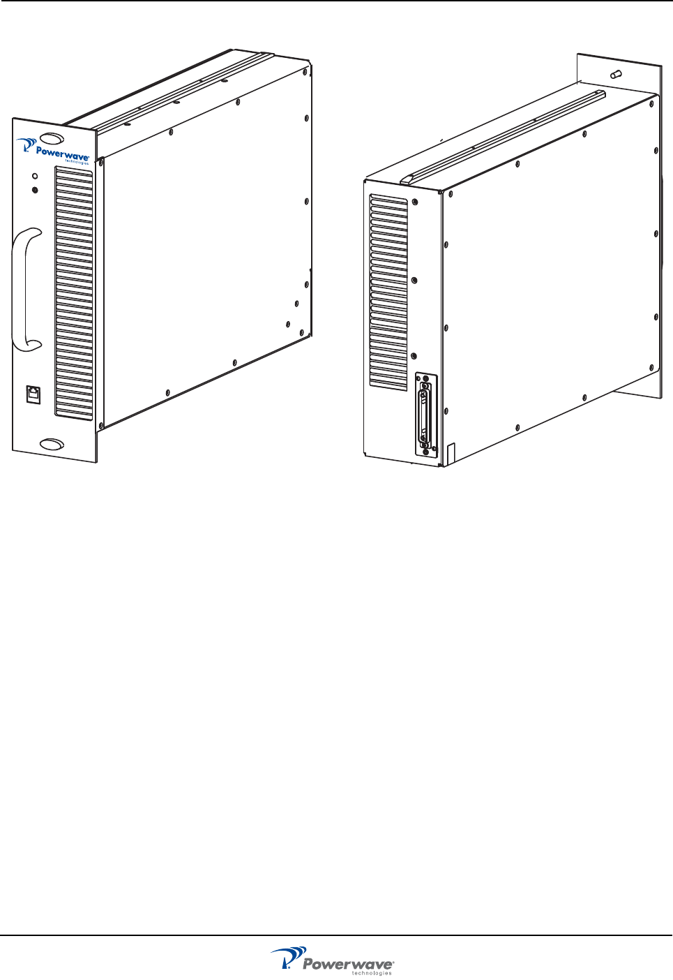
Figure 1-1 MCPA Front and Rear Views ..................................................................................................1-2
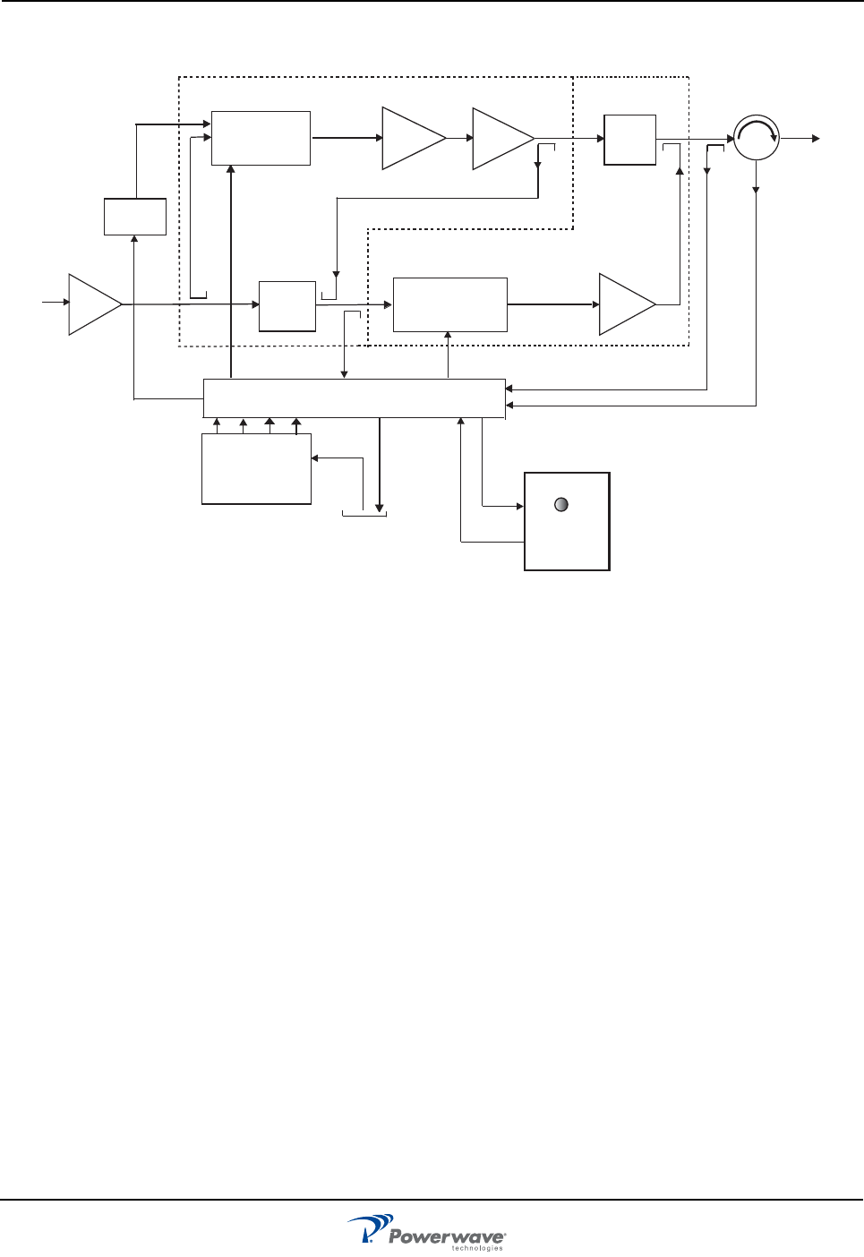
Figure 1-2 MCPA Functional Block Diagram ............................................................................................1-3
Figure 2-1 MCPA Controls and Indicators ................................................................................................2-1
Figure 2-2 MCPA Interface Connector .....................................................................................................2-3
Figure 3-1 MCPA Quarter-turn fasteners and Connectors .......................................................................3-2

G3L-850-180 List of Tables
044-05421 Rev A
v
LIST OF TABLES
Table 1-1. Derating....................................................................................................................................1-5
Table 2-1 MCPA Controls and Indicators ..................................................................................................2-2
Table 2-2 MCPA Alarm States ..................................................................................................................2-2
Table 2-3 MCPA Connector Pinouts .........................................................................................................2-3
Table 3-1 Unpacking the MCPA ................................................................................................................3-1
Table 3-2 Install the MCPA........................................................................................................................3-2
Table 3-3 Initial MCPA Start-up.................................................................................................................3-2
Table 4-1 Recommended Periodic Maintenance ......................................................................................4-1
Table 4-2 Troubleshooting.........................................................................................................................4-1
Table 4-3 MCPA Removal and Replacement............................................................................................4-2
Table 5-1 MCPA Specifications.................................................................................................................5-1

044-05454 Rev A 1
Chapter 1
Product Description
Introduction
This manual contains information and procedures for the installation, operation, and maintenance of the G3L-
850-180 Multi-Carrier Power Amplifier (MCPA).
Scope of Manual
This manual is intended for use by service technicians familiar with similar types of equipment. It contains
service information required for the equipment described and is current as of the printing date. Changes which
occur after the printing date may be incorporated by a complete manual revision or alternatively as additions.
The manual is organized into the following chapters:
❑ Chapter 1 - Product Description
❑ Chapter 2 - Controls and Indicators
❑ Chapter 3 - Installation
❑ Chapter 4 - Maintenance
❑ Chapter 5 - Specifications
Product Description
The MCPA shown in Figure 1-1 MCPA Front and Rear Views is a linear, feed-forward multi-carrier power
amplifier that operates in a 25MHz frequency band from 869 MHz to 894 MHz with an instantaneous bandwidth
of 25 MHz. The instantaneous bandwidth is the maximum frequency band in which any two or more signals can
occupy. The instantaneous bandwidth of the MCPA is set automatically.
The MCPA is modular in design and ideally suited for use in GSM, UMTS, EDGE, CDMA, and W-CDMA base
stations. The MCPA provides a gain of 63 dB to provide a 210 watt output at 27 VDC and 25 °C with seven GSM
+ one EDGE signal; 150 watts with 7.5 dB PAR signal of any combination of EDGE, GSM, W-CDMA, with a
maximum of four EDGE, a maximum of eight GSM/EDGE and a maximum of two W-CDMA signals; and 130
watts with a maximum of four W-CDMA or eight CDMA signals. Refer to Figure 1-2 MCPA Functional Block
Diagram for the MCPA functional block diagram. Refer to Chapter 5 for the MCPA specifications.
Functional Description
The MCPA is a self-contained module typically operated in parallel with other identical MCPAs as part of a
subrack assembly.
The MCPA consists of the following major functions:
❑ Preamplifier
❑ Main and error amplifiers
❑ Feed-forward loop control circuits
❑ Pilot tone generator
❑ Controller
G3L-850-180 Functional Description
044-05454 Rev A 1-2
STATUS
RESET
PC I/O
ON
OFF
Figure 1-1 MCPA Front and Rear Views
Front Rear
G3L-850-180 Functional Description
044-05454 Rev A 1-3
Preamplifier
The carrier (RF In) is applied to the input port of the MCPA and fed to the preamplifier stage where it is amplified
using two stages of class A mode amplifiers. The output of the preamplifier is split into two paths, one to the
main amplifier and one to the error amplifier.
Main and Error Amplifiers
The main amplifier provides the balance of gain and power in the 869 MHz to 894 MHz frequency band, using
class AB amplification for maximum efficiency. The error amplifier and feed forward loops correct signal non-
linearities introduced by the class AB main amplifier.
In the error amplifier, which operates in class A mode, the RF signal is coupled to an attenuator and phase
shifter in the first feed-forward loop, phase shifted by 180 degrees and then amplified in the premain amplifier.
The output from the pre-main amplifier is fed to the class AB main amplifier and then sampled using a coupler.
The signal (RF sample) is combined with the main input signal and input to the second feed-forward loop.
There, the RF sample is attenuated, phase shifted 180 degrees, and fed to the error amplifier where it is
amplified to a level identical to the sample output from the main amplifier. The output from the error amplifier
(Error Out) is coupled back and added to the output from the main amplifier, with the control loops continuously
making adjustments to cancel out any distortion in the final output signals.
Feed-forward Loop Control Circuits
The primary function of the first loop is to amplify the carrier signals and isolate an error signal for the second
loop. It does this by amplifying the carrier signals and isolating an error signal which is passed to the second
loop. The first loop control section phase shifts the main input signals by 180 degrees and constantly monitors
the output for correct phase and gain.
Preamp Delay Second Loop
Phase and Gain
Error
Amplifier
First Loop
Phase and Gain
Reflected Power (VSWR)
RF Out
Pilot Tone
Generator
RF Sample
Forward Power / Pilot Tone Detect
RF In
Premain
Amplifier
Error Out
Delay
Filter
Main
Amplifier
System
Faults
Front Panel
LED
Status
ON/OFF/RESET
Switch
Control
VDC VDC VDCVDC +27 VDC
User
Interface
Pilot Tone
Controller
First Loop
Detection
FIRST LOOP SECOND LOOP
First Loop
Control
Second Loop
Control
-5
+5+9+15
Figure 1-2 MCPA Functional Block Diagram

G3L-850-180 Cooling
044-05454 Rev A 1-4
The primary function of the second loop is to amplify the error signal to cancel out spurious products developed
in the main amplifier. The input signal is amplified by a preamplifier and fed to a coupler and delay line. The
signal from the coupler is fed to the attenuator and phase shifter in the first loop.
The second loop control section obtains a sample of the distortion added to the output signals by the main
amplifiers. The signal is phase shifted 180 degrees, then fed to the error amplifier where it is amplified to the
same power level as the input sample. The signal is then coupled to the main amplifier output. The final output
is monitored by the second loop and adjusted to ensure that the signal distortion and intermodulation distortion
on the final output is cancelled out.
During routine operation, all normal variations are automatically compensated for by the feed-forward loop
control. If large variations occur beyond the adjustment range of the loop control, the controller shuts down the
MCPA RF section and a loop fault is reported to the system.
Pilot Tone Generator
The pilot tone is an internally generated signal with a predetermined frequency, phase, and amplitude is known.
If the pilot signal is suppressed at the amplifier output, then the distortion created by the main amplifier is also
suppressed.
The pilot tone signal is injected into the first loop and detected at the feedforward output of the second loop. The
pilot tone is coupled off of the main amplifier creating a second pilot tone that is attenuated and phase shifted
180 degrees to be used as the reference. The second pilot tone is amplified in the error amplifier and mixed with
the signals from the main signal path.
The first and second pilot tones should cancel each other out in an ideal situation. If the output detector senses
that the pilot tones do not cancel each other out, the information feeds back to control the gain and phase of
both the main and error amplifier paths minimizing output distortion.
Controller
The controller constantly compares the active RF paths with internal references for dynamic correction of small
variations through the RF feedback control circuits to maintain constant gain, and also provides the alarm
monitoring and control for the MCPA.
A front panel mounted tri-color LED provides MCPA operational status to the local operator. The OFF/ON/
RESET switch allows the operator to power on, power off or reset the MCPA. System faults are sent to a remote
location through the user interface.
Cooling
The MCPA components are mounted on a heatsink and cooled by forced air flowing over the heatsink fins.
System fans draw external air through the MCPA front panel inlet and exhaust air through the MCPA rear panel
outlet. The internal temperature is monitored to keep the MCPA within the specified operating temperature.
Power Distribution
The host system provides +27 VDC power for the MCPA. The DC/DC converter and voltage regulator in the
MCPA converts the +27 VDC to +15 VDC, +9 VDC, +5 VDC, and -5 VDC for internal use. The MCPA has no
built-in short-circuit protection.
The MCPA operates at full power if the system DC supply is within 26 to 30 VDC. The MCPA shuts down if the
applied DC power is less than 21.5 VDC or greater than 30.5 VDC.
Derating
MCPA RF power output is derated if the applied DC power drops below 26 VDC, but remains above 21.5 VDC.
RF output is reduced by 1.0 dB between 25 to 25.9 VDC, by 1.5 dB between 24 to 24.9 VDC and by 2.0 dB
between 21.5 to 23.9 VDC.

G3L-850-180 Power Distribution
044-05454 Rev A 1-5
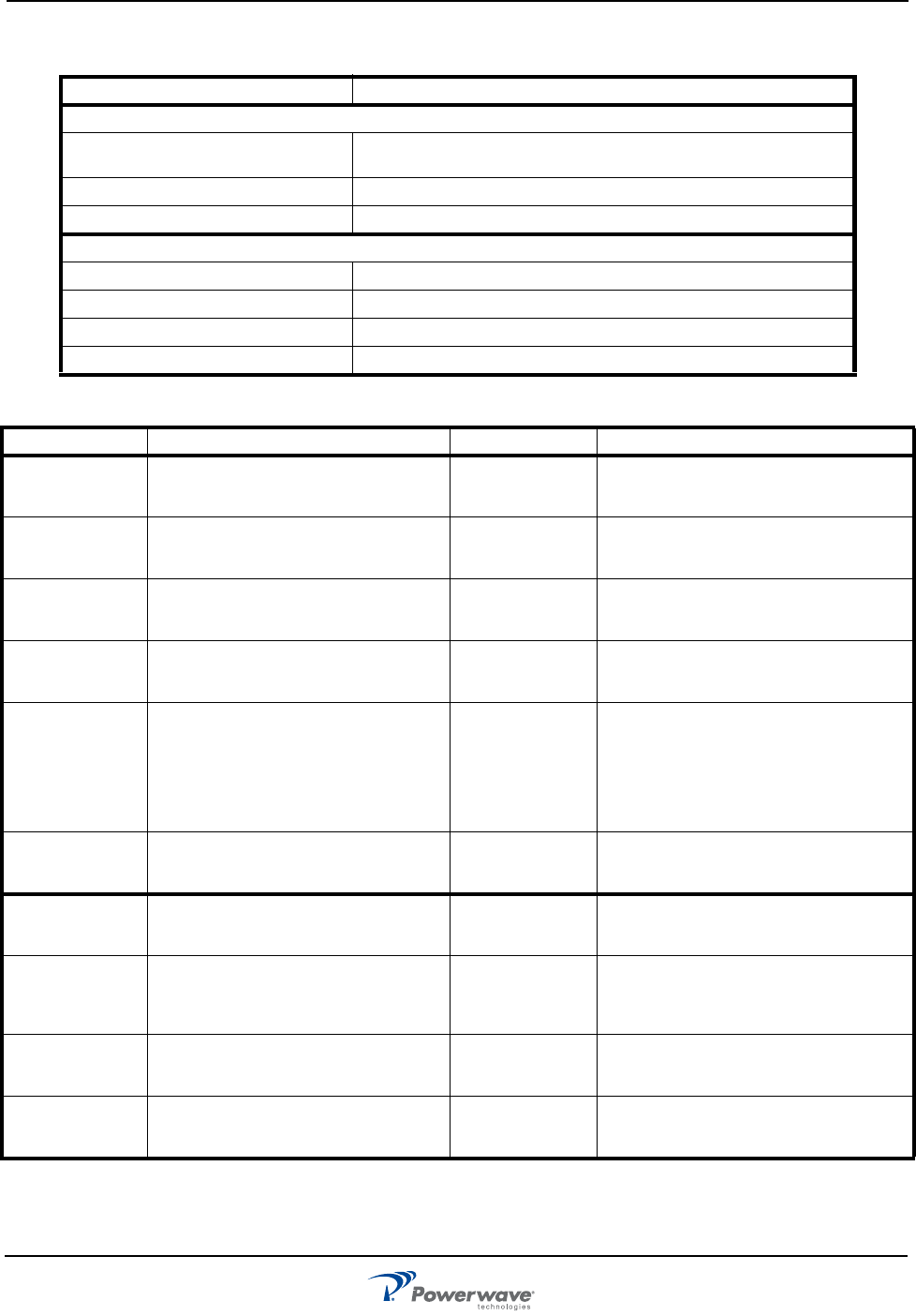
Table 1-1. Derating
DC Voltage RF Output Derating
26 VDC to 30 VDC None
25 VDC to 25.9 VDC 1.0 dB
24 VDC to 24.9 VDC 1.5 dB
21.5 VDC to 23.9 VDC 2.0 dB
Below 21.5 VDC No Power/Alarm Condition
044-05454 Rev A 2-1
Chapter 2
Controls and Indicators
Introduction
This chapter contains descriptions of the G3L-850-180 Multi-Carrier Power Amplifier (MCPA) controls and
indicators.
MCPA Controls and Indicators
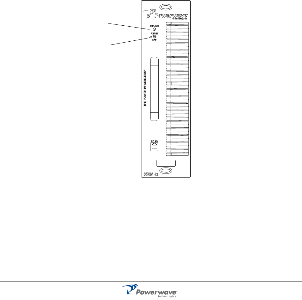
The location of the MCPA controls and indicators are illustrated in Figure 2-1 and listed with descriptions in
Table 2-1.
MCPA Alarms
MCPA alarm conditions are reported to the system as logic level signals through the rear connector. The front
panel LED provides a visual reference for the operator of MCPA status. Refer to Table 2-1 for a listing of LED
states. Refer to Table 2-2 for a listing of Alarm states.
180W
Figure 2-1 MCPA Controls and Indicators
Multicolor
OFF/ON/RESET Switch
LED Status Indicator
G3L-850-180 MCPA Controls and Indicators
044-05454 Rev A 2-2
Table 2-1 MCPA Controls and Indicators
Controls and Indicators Description
Toggle Switch, Three Position
RESET (Up) Resets
MCPA
. LED indicates boot mode (red), then turns solid
green
ON (Center) Enables MCPA. LED indicates solid green
OFF (Down) Disables MCPA. LED Indicates solid red
LED, Status
Green (solid) MCPA normal operation, no alarm
Green (blinking) Standby (disabled from front panel or disable command)
Yellow (solid) Minor Alarm - APC function enabled
Red (solid) Major alarm - no service, MCPA disabled
Table 2-2 MCPA Alarm States
Alarm Definition Alarm type/LED Auto-Recovery
Output
Overpower
Disables MCPA immediately if
output power is >+2 dB over rated
output RF power.
Major
(Red)
No auto recovery. Requires front
panel manual reset, or by host system
command.
Automatic
Power Control
(APC)
Enabled if output power is > 52.67
dBm.*
Minor
(Yellow)
MCPA auto-recovers when output
power drops below rated maximum
output power.
Input
Overdrive
Disables MCPA immediately if input
RF drive is >-4.95 dB
Major
(Red)
No auto recovery. Requires front
panel manual reset, or by host system
command.
High
Temperature
Disables MCPA if sensor
temperature is > +85° C.
Major
(Red)
MCPA auto-recovers when sensor
temperature drops to less than +75
°C.
High Reverse
Power
Disables MCPA if the reverse RF
output power is higher than 49 dBm
for a duration of 1-minute.
Minor (Yellow)
during 1-
minute
validation
period then
changes to
Major (Red)
No auto-recovery. Requires front
panel manual reset, or by host system
command. Reverse power must be <
48.3 dBm.
Exceed
Maximum
Voltage
Disables MCPA immediately if
supply DC voltage > +30.5 VDC.
Major
(Red)
Auto-recovery when supply voltage
drops to < +29.5 VDC.
Below
Minimum
Voltage
Disables MCPA immediately if
supply DC Voltage < +20.5 VDC
Major
(Red)
Auto-recovery when supply voltage
increases to >+24.0 VDC
Loop Fail
(Linearization
Alarm)
Disables MCPA if loop convergence
fails.
Major
(Red)
Auto-recovery when loop converges.
MCPA tries to auto recover ten times
before permanent shut down. Two
minutes and 5 seconds for each try.
Internal DC
Fail
Alarm if internal voltages fail or out
of range.
Minor
(None)
Auto-recovery once voltage is within
range. No shutdown until linearization
alarm occurs.
Device Fail Alarm if one or more output power
devices fail.
Minor
(None)
No auto-recovery. No shutdown until
linearization alarm occurs.
*Note: If MCPA cannot compensate gain to maintain compliance, Output Overpower or Input Overdrive faults protect
MCPA.
G3L-850-180 MCPA Controls and Indicators
044-05454 Rev A 2-3
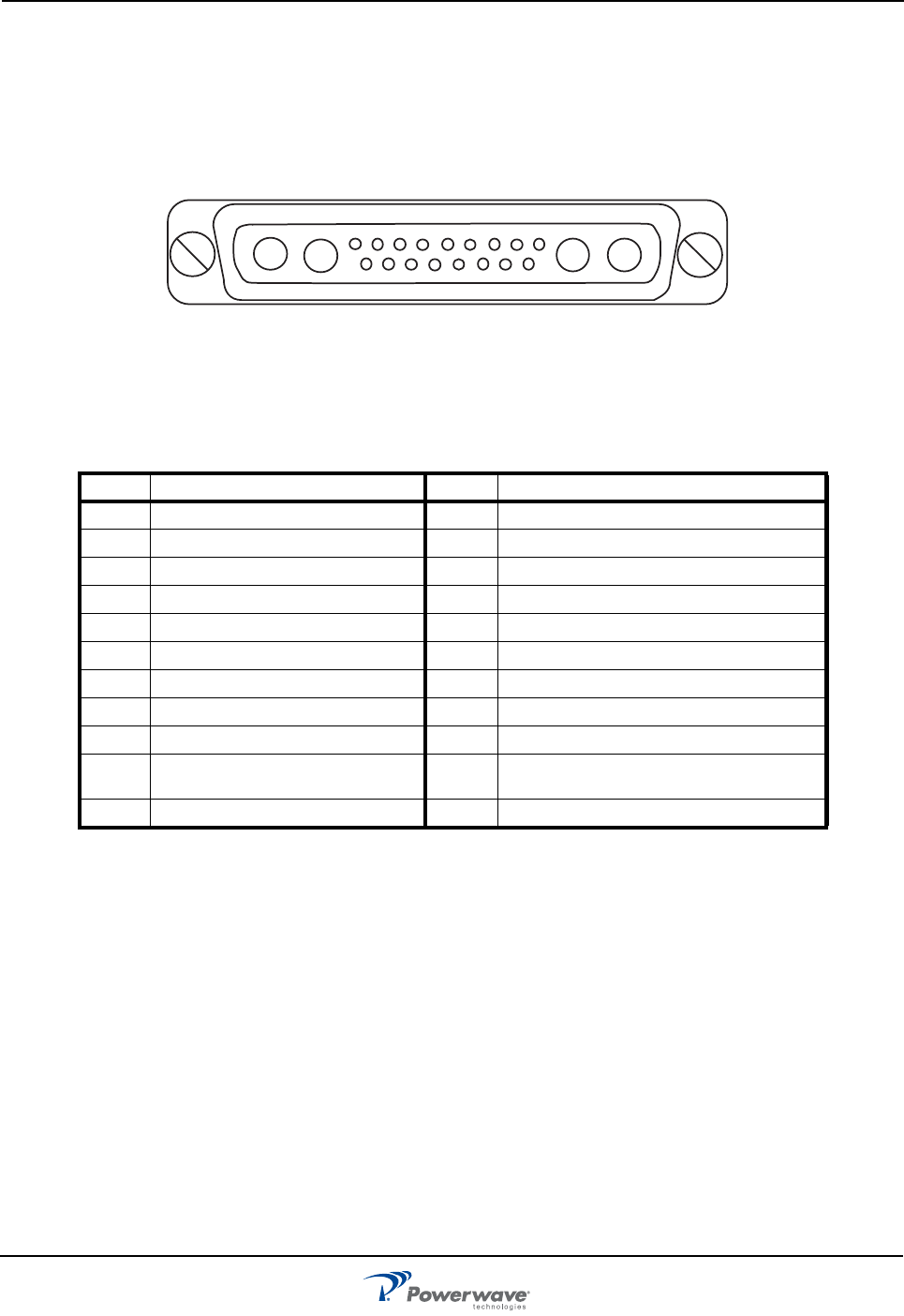
MCPA Connectors
The MCPA power, alarm, control, and RF connections are made through a D-sub combination male interface
connector located on the rear of the MCPA. Pin assignments are illustrated in Figure 2-2 MCPA Interface
Connector and listed in Table 2-3. Alarms are interpreted and generated by the MCPA and reported to the base
station as a system level alarm. The PC I/O RJ-11 connector is for factory use only.
Table 2-3 MCPA Connector Pinouts
Pin Function Pin Function
A1 RF Input (Coaxial Contact) 8SUMMARY_FAULT (Fault info) TTL
A2 +27 VDC (Power Contact) 9DC_ON/OFF (On/Off)
A3 Ground (Power Contact) 10 PAU_RST (System Reset) TTL
A4 RF Output (Coaxial Contact) 11 NC
1TX_H (RS-485) 12 NC
2TX_L (RS-485) 13 AMP_A0 (PAU ID)
3GND 14 AMP_A1 (PAU ID)
4RX_H (RS-485) 15 AMP_A2 (PAU ID)
5RX_L (RS-485) 16 NC
6GND 17 PAU_TEMP (Voltage for
Temperature Measurement)
7MOD_DET (Module Detection)
123
A1 A2 A3 A4
456789
10 11 12 13 14 15 16 17
Figure 2-2 MCPA Interface Connector
044-05454 Rev A 3-1
Chapter 3
Installation
Introduction
This chapter contains unpacking, inspection, startup and installation procedures for the G3L-850-180 Multi-
Carrier Power Amplifier (MCPA).
❑ Review this chapter prior to equipment installation.
❑ Review any government and local codes applicable to this installation.
❑ Read the instructions in this Chapter and Chapter 4 before operating the equipment.
Unpacking and Inspection
Perform the steps in Table 3-1 to unpack and inspect the MCPA.
Damaged Equipment
If the MCPA is damaged, a claim should be filed with the carrier when the extent of any damage is assessed.
Contact the factory for a return material authorization (RMA). Refer to Chapter 4 for the return procedure.
Air Conditioning Requirements
The MCPA generates 2770 BTUs of heat at 36 A, 27 V and 180 W average RF power output. The MCPA
operates within the extended low temperature and high temperature environments as listed in Chapter 5.
MCPA Installation Instructions
The modular MCPA can be installed in a variety of systems. All system connections to the MCPA are made
through the MCPA rear connector, no additional wiring is required. Perform the steps in Table 3-2 to install the
MCPA. Refer to Figure 3-1 MCPA Quarter-turn fasteners and Connectors for quarter-turn fastener position and
switch location.
Table 3-1 Unpacking the MCPA
Step Action
1
Carefully open container and remove MCPA.
2
Visually inspect MCPA for damage that may have occurred during shipment.
Check for evidence of water damage, bent or warped chassis, loose screws or
nuts, or extraneous packing material in connectors. If possible, inspect equipment
in the presence of the delivery person.
3
If possible, retain all packing material that can be reused for repackaging
components.
CAUTION: Do not slam the MCPA into the system subrack during installation. Using
excessive force can damage the MCPA interface connector.
G3L-850-180 Initial Start-up and Operating Procedures
044-05454 Rev A 3-2
Initial Start-up and Operating Procedures
Perform the MCPA initial start-up per the instructions in Table 3-3.
Table 3-2 Install the MCPA
Step Action
1
Set MCPA OFF/ON/RESET switch to the OFF (down) position.
2
Ensure quarter-turn fasteners are in unlocked position.
3
Lift and insert MCPA into the subrack. Turn the quarter-turn fasteners to locked
position to secure MCPA into subrack.
CAUTION: Before applying power, ensure input and output cables are properly terminated at
the Duplexer front panel. Do not operate MCPA without a load attached. Excessive input
power may damage the MCPA. Refer to Chapter 5 for input power requirements.
Table 3-3 Initial MCPA Start-up
Step Action
1Verify all system input and output cables are properly connected.
2Verify +27 VDC (+/- 1 VDC) supply is available.
3Set MCPA OFF/ON/RESET switch io ON (center) position.
4Allow MCPA to warm-up for a minimum of two minutes before taking power readings.
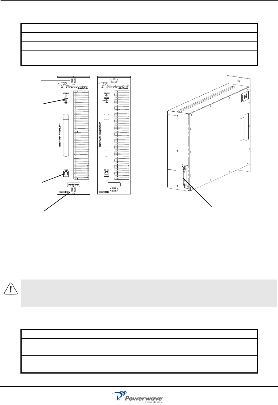
180W
180W
Figure 3-1 MCPA Quarter-turn fasteners and Connectors
Unlocked Locked
RF Switch:
RJ-11
Connector
(Factory use only)
Quarter-turn
fastener
RESET
ON
OFF
Quarter-turn
fastener
Interface
Connector
044-05454 Rev A 4-1
Chapter 4
Maintenance
Introduction
This chapter contains instructions for periodic maintenance, testing and troubleshooting for the G3L-850-180
Multi-Carrier Power Amplifier (MCPA).
Periodic Maintenance
Periodic maintenance requirements for the MCPA are listed in Table 4-1.
MCPA Performance Tests
MCPA Performance tests are only performed at the factory. Refer to the troubleshooting instructions below.
Troubleshooting
Perform the instructions in Table 4-2 in the case of an MCPA fault or alarm.
MCPA Removal and Replacement
Perform the instructions in Table 4-3 to remove and replace a MCPA.
NOTE Check your sales order and equipment warranty before attempting to service or repair the
unit. Do not break the seals on equipment under warranty or the warranty will be null and
void. Do not return equipment for warranty or repair service until proper shipping
instructions are received from the factory.
Table 4-1 Recommended Periodic Maintenance
Task Interval Action
Cleaning 3 Months Inspect for debris especially around front panel vents. Remove
dust with a soft cloth/brush or vacuum cleaner
Performance tests Optional Perform testing in accordance with the information below.
Table 4-2 Troubleshooting
Step Action
1Check for proper DC supply voltage.
2Set the OFF/ON/RESET switch momentarily to RESET (Up) position.
3Contact your field representative or the factory if fault does not clear.
CAUTION: Do not slam the MCPA into the system during installation. Using excessive
force can damage the MCPA connector.
G3L-850-180 Return For Service Procedures
044-05454 Rev A 4-2
Return For Service Procedures
When returning products to Powerwave, the following procedures will ensure optimum response.
Obtaining An RMA
A Return Material Authorization (RMA) number must be obtained prior to returning equipment and to reduce
delays in receiving repair service. Please contact our Repair Department at (714) 466-1000 to obtain this
number, or FAX your request to (714) 466-5816.
Repackaging for Shipment
To ensure safe shipment of a component, it is recommended that the original packing materials be reused If
this is not possible, use suitable shipping cartons and foam inserts to prevent damage in transit.
CAUTION: When removing the MCPA from the system, support the MCPA to prevent the
rear of the MCPA from suddenly dropping when the guide rail disengages from the track.
Dropping the MCPA can damage the rear multi-pin connector. The MCPA weighs
approximately 20 lbs. (9.1 kg).
Table 4-3 MCPA Removal and Replacement
Step Action
1Set MCPA OFF/ON/RESET switch to OFF (down).
2Loosen two quarter-turn fasteners that secure MCPA to the subrack.
3With steady even pressure, use handle on front of the MCPA to pull the MCPA out of the
system.
4To replace MCPA, set MCPA OFF/ON/RESET switch to OFF (down).
5Turn quarter-turn fasteners to Unlocked position.
6Insert MCPA into subrack. Turn quarter-turn fasteners to locked position to secure MCPA.

044-05454 Rev A 5-5
Chapter 5
Specifications
Multi-Carrier Power Amplifier Specifications
The performance and physical specifications for the G3L-850-180 MCPA are listed in Table 5-1.
.
Table 5-1 MCPA Specifications
Electrical Specifications/Features
Operating Frequency Band 869-894 MHz
Instantaneous Bandwidth 25 MHz
Air Interface GSM, EDGE, CDMA2000/CDMA, WCDMA, LTE
RF Output Power 210 Watts Max, 180 Watts Nominal
Maximum Input -4.95 dBm
Duty Cycle Continuous
BTUs 2770 at 36 Amps, 27 V and 180 W nominal RF power output
RF Gain 63 dB ±1 dB
Intermodulation Distortion -62 dBc (Max.)
Harmonics -13 dBm (Max.) 1 MHz Bandwidth; -50 dBc (Max.)
Out of Band Spurious -60 dBc (Max) ITU-R, SM329-9, Category A
Gain Flatness ±0.5 dB (Max.)
Gain Variation over Temperature ±0.5 dB (Max.)
Input Return Loss 14 dB (Min.)
Output Return Loss 10 dB (Min.)
Input Voltage Range +22 VDC to +30 VDC nominal; Operational range of 22 VDC to 30
VDC, performance derated below 26 VDC.
MCPA disables at less than 21.5 VDC or greater than+30.5 VDC
DC Current 29 Amps at 27 V and 180 W nominal RF power output.
Efficiency 23%
Mechanical Specifications/Features
Controls Three position toggle switch: OFF/ON/RESET
Alarm Indication LED; Green (normal), Yellow (minor alarm), Red (Major alarm)
Platform Compatibility Velocity Power Amplifier (PA) will reduce power level to 120 W (Max.)
if placed in a Harley/Python subrack. PA will perform at rated power
levels with Software upgrade for subrack
RF Input / Output / Status / Alarm /
Control / DC Input Connector
21-pin D-subminiature combo connector
DImensions 354.6 mm high, 99 mm wide, 499.9 mm deep (including handles)
(13.96” H X 3.9” W X 19.7” D)
Weight 12.97 kg (28.5 lbs)
G3L-850-180 Industry Canada
044-05454 Rev A 5-5
Industry Canada
20dB Gain Bandwidth measurement = 167 MHz:
Rated output power = 200 Watts.
Input impedance = 50 ohms.
Output impedance = 50 ohms.
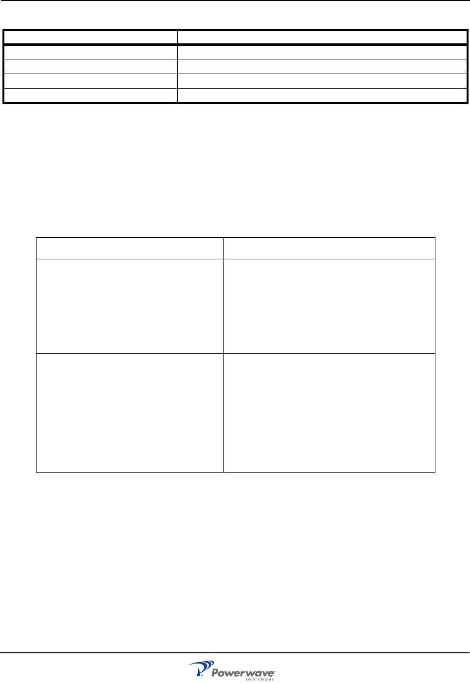
Environmental Specifications/Features
Operating Temperature Range -20 ºC. to +50 ºC
Storage Temperature -40 ºC. to +70 ºC
Operating Humidity, Normal 5% to 95% relative humidity (non-condensing)
Storage Humidity 5% to 95% relative humidity (non-condensing)
English French
This device complies with Industry Canada
licence-exempt RSS standard(s). Operation
is subject to the following two conditions: (1)
this device may not cause interference, and
(2) this device must accept any interference,
including interference that may cause unde-
sired operation of the device.
Le présent appareil est conforme aux CNR d'Indus-
trie Canada applicables aux appareils radio
exempts de licence. L'exploitation est autorisée aux
deux conditions suivantes : (1) l'appareil ne doit pas
produire de brouillage, et (2) l'utilisateur de l'appar-
eil doit accepter tout brouillage radioélectrique subi,
même si le brouillage est susceptible d'en compro-
mettre le fonctionnement.
The Manufacturer's rated output power of
this equipment is for single carrier operation.
For situations when multiple carrier signals
are present, the rating would have to be re-
duced by 3.5 dB, especially where the out-
put signal is re-radiated and can cause
interference to adjacent band users. This
power reduction is to be by means of input
power or gain reduction and not by an atten-
uator at the output of the device.
La puissance de sortie nominale indiquée par le
fabricant pour cet appareil concerne son fonc-
tionnement avec porteuse unique. Pour des appa-
reils avec porteuses multiples, on doit réduire la
valeur nominale de 3,5 dB, surtout si le signal de
sortie est retransmis et qu'il peut causer du brouil-
lage aux utilisateurs de bandes adjacentes. Une
telle réduction doit porter sur la puissance d'entrée
ou sur le gain, et ne doit pas se faire au moyen d'un
atténuateur raccordé à la sortie du dispositif.
Table 5-1 MCPA Specifications (Continued)

© Copyright 2011, Powerwave Technologies, Inc. All rights reserved. Powerwave, Powerwave Technologies, and the Powerwave logo are registered
trademarks of Powerwave Technologies, Inc. Clean Site, Connecting the Wireless World, Intellimast, InView Management System, LinkNet, MicroFlex,
NetWay, Nexus, PowerBoost, Performance Boost, RapidFlex, SubTerra and VersaFlex are trademarks of Powerwave Technologies, Inc. LTE is a
registered trademark of European Telecommunications Standards Institute. Other trademarks referenced are the property of their respective owners. All
specifi cations are subject to change without notice. Please contact your Powerwave representative for complete performance data.
Main Asia-Pacific Office
2018-2019 Chevalier Commercial Building
8 Wang Hoi Road, Kowloon Bay,
Kowloon, Hong Kong
+852 2512 6123
+852 2575 4860 FAX
Main European Office
Knarrarnasgatan 7 8tr.
164 40 Kista, Sweden
+46 8 540 822 00
+46 8 540 824 91 FAX
Worldwide Corporate Headquarters
1801 East St. Andrew Place
Santa Ana, CA 92705 USA
+1 714 466 1000
+1 714 466 5800 FAX
www.powerwave.com