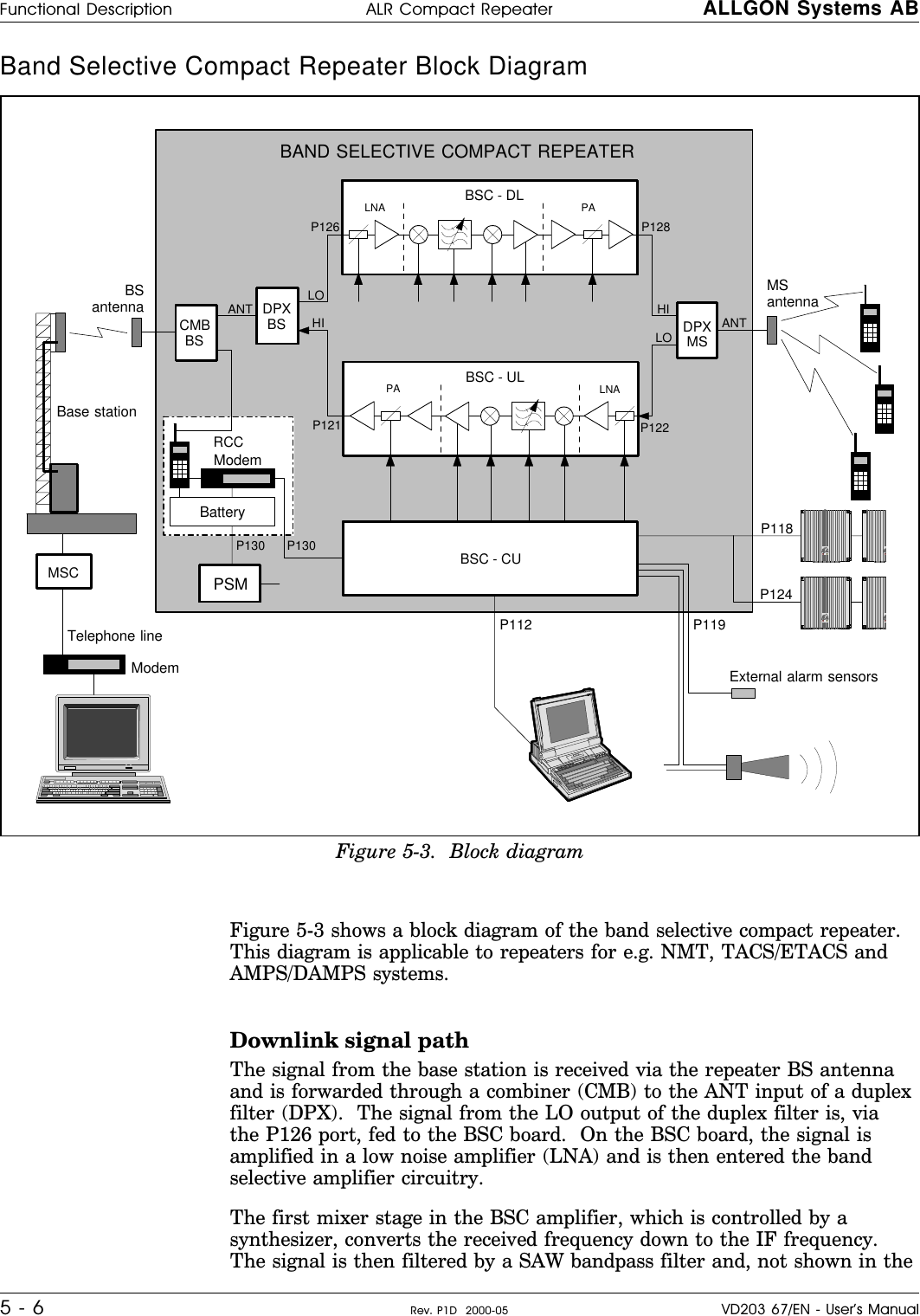
Powerwave Technologies ALR3200 PCS Channel Selective Repeater User Manual ARL Compact Repeater User s Manual

Powerwave Technologies Inc. PCS Channel Selective Repeater ARL Compact Repeater User s Manual

manuals

9WIVkW1ERYEP%06'SQTEGX6ITIEXIV0S[4S[IV&ERH7IPIGXMZI6ITIEXIV)RKPMWLVD203 67/EN
User’s ManualALR Compact RepeaterLow Power Band Selective Repeater–EnglishALLGON Systems AB ALR Compact RepeaterVD203 67/EN - User’s Manual Rev. P1D  2000-05 i
This document describes installation, commissioning and the design of the Allgon ALR Compact Repeater.Communication between the Allgon ALR Compact Repeater and an operator is carried out either by using Allgon OMT32(Operation and Maintenance Terminal), or Allgon OMS (Operation and Maintenance System). OMT32 is described in theAR Repeaters and OMT32, User’s Manual.  OMS is described in the Advanced Repeater OMS, User’s Manual.Hardware and software mentioned in this document are subjected to continuous development and improvement.Consequently, there may be minor discrepancies between the information in the document and the performance anddesign of the product. Specifications, dimensions and other statements mentioned in this document are subject to changewithout notice.In this document, the ’<>’ brackets are used to indicate function keys contrary to a series of key strokes’<Del>’ = the Del(ete) key, ’Del’ = D, e, l.Allgon and its suppliers shall not be liable for any damages related to the software or hardware, or for any other damages whatsoever caused of the use of orinability to use any Allgon product.  This is applicable even if Allgon has been advised of the damage risk.  Under any circumstances, Allgon’s entire liabilityshall be limited to replace such defective software or hardware which was originally purchased from Allgon.Teflon is a registered trademark of Du Pont.  Other trademarks mentioned in this document are trademarks or registered trademarks of their respectiveowners.This document is produced by El, Tele & Maskin Ingenjörsfirma AB, Huddinge, Sweden.Printed in Sweden.Allgon Systems AB, Box 541, S-183 25 Täby, SwedenPhone: +46 8 540 822 00 – Fax: +46 8 540 824 85 – Internet: www.allgon.comThis document or parts of it may not be reproduced without the written permission of Allgon System AB.Infringements will be prosecuted.  All rights reserved.Copyright © Allgon Systems AB, Sweden, 1994-2000.ALR Compact Repeater ALLGON Systems ABii Rev. P1D  2000-05 VD203 67/EN - User’s Manual
ContentsAbbreviations ...............................................................................................................  v1. Safety ....................................................................................................................... 1-1Static Electricity  ..................................................................................................  1-22. Introduction .............................................................................................................  2-1Repeater Types  ..................................................................................................  2-2Using Repeaters  .................................................................................................  2-3Shaded Area .................................................................................................  2-4Sports Arena ...................................................................................................  2-53. Installation ................................................................................................................  3-1Siting the Repeater ............................................................................................  3-1Sunshine .........................................................................................................  3-1Shelter .............................................................................................................  3-1Outdoor Installation and Service Limitations ..............................................  3-1Dimensions and Weights ...................................................................................  3-2Mounting .............................................................................................................  3-3Connection  ........................................................................................................  3-6Connection Ports and Station Ground  ............................................................  3-9Station Ground  ..............................................................................................  3-9P112 PC Port ..................................................................................................  3-10P113 Parking Device  .....................................................................................  3-10P118 Repeater to Repeater Link Port ..........................................................  3-10P119 Alarm Port .............................................................................................  3-11P120 Door Switch  ..........................................................................................  3-12P124 Repeater to Repeater Link Port ..........................................................  3-12P130 RCC Port ...............................................................................................  3-12Mains Breakdown Relay  ....................................................................................  3-134. Commissioning ........................................................................................................  4-1Starting the Repeater  ........................................................................................  4-2Indicators .......................................................................................................  4-3Repeater Configuration  ....................................................................................  4-45. Functional Description and Design  .......................................................................  5-1Repeater Design  ................................................................................................  5-2Single Band Repeater Units ..........................................................................  5-3Dual Band Repeater Units  ............................................................................  5-4Block Diagram ....................................................................................................  5-5Downlink Signal Path  .....................................................................................  5-5Uplink Signal Path  ..........................................................................................  5-5Band Selective Compact Repeater Block Diagram  .................................  5-6RCC ................................................................................................................  5-7R2R .................................................................................................................  5-7Alarm ..............................................................................................................  5-8Repeater Setup  .............................................................................................  5-8Board and Unit Descriptions  .............................................................................  5-9ALLGON Systems AB ALR Compact RepeaterVD203 67/EN - User’s Manual Rev. P1D  2000-05 iii
CMB - Combiner  ...........................................................................................  5-9DPX - Duplex Filter .........................................................................................  5-9BSC Band Selective Compact Board  .........................................................  5-10LNA - Low Noise Amplifier .............................................................................  5-13PA - Power Amplifier ......................................................................................  5-14Repeater CU Software and Hardware Compatibility .................................  5-15Cabling ...............................................................................................................  5-16Compact Repeater With RCC Unit  .............................................................  5-16Compact Repeater Without RCC Unit  ........................................................  5-17R2R, Repeater To Repeater Link .......................................................................  5-18Installation ......................................................................................................  5-18Configuration .................................................................................................  5-186. Optionals ..................................................................................................................  6-1RCC, Remote Communication Control Unit ...................................................  6-2OMT32, Operation and Maintenance Terminal ..............................................  6-3OMS, Operation and Maintenance System ....................................................  6-3Battery Backup ...................................................................................................  6-3Fiber Optic Unit  ..................................................................................................  6-37/16" Antenna Cable Connectors  ...................................................................  6-3Index ..............................................................................................................................  I-1Questionnaire ..............................................................................................................  Q-1ALR Compact Repeater ALLGON Systems ABiv Rev. P1D  2000-05 VD203 67/EN - User’s Manual
FiguresFigure 2-1.  Allgon ALR Compact Repeater  ..............................................................  2-1Figure 2-2.  Repeater coverage of shaded area .....................................................  2-4Figure 2-3.  Repeater in sports arena  ........................................................................  2-5Figure 3-1.  Repeater dimensions ...............................................................................  3-2Figure 3-2.  Attaching the repeater to a wall  ...........................................................  3-3Figure 3-3.  Attaching the bracket to a pole ............................................................  3-4Figure 3-4.  Attaching the bracket to a mast  ...........................................................  3-4Figure 3-5.  Attaching the repeater to the bracket ..................................................  3-5Figure 3-6.  MS and BS antenna connections ...........................................................  3-6Figure 3-7.  Connection ports and station ground  ...................................................  3-9Figure 3-8.  Mains breakdown relay connection  ......................................................  3-13Figure 4-1.  Indicators in the cabinet .........................................................................  4-3Figure 5-1.  Single band repeater units  .....................................................................  5-3Figure 5-2.  Dual band repeater units ........................................................................  5-4Figure 5-3.  Block diagram  ..........................................................................................  5-6Figure 5-4.  BSC, Band Selective Compact board ...................................................  5-10Figure 5-5.  LNA, Low Noise Amplifiers  .......................................................................  5-13Figure 5-6.  PA, Power Amplifiers .................................................................................  5-14Figure 5-7.  Cabling with RCC unit  .............................................................................  5-16Figure 5-8.  Cabling without RCC unit  .......................................................................  5-17Figure 5-9.  Repeater to Repeater Link ......................................................................  5-18Figure 6-1.  The RCC unit  ............................................................................................  6-2ALLGON Systems AB ALR Compact RepeaterVD203 67/EN - User’s Manual Rev. P1D  2000-05 v
Abbreviations Abbreviations used in this manual, in the software, and in the repeater:AGC Automatic Gain ControlAMPS Advanced Mobile Phone ServiceBCCH Broadcast Control Channel (GSM broadcast channel time slot)BS Base Station, BS antenna = towards the base stationBSC Band Selective Compact repeater board for adjustable bandwidthCDMA Code Division Multiple AccessCMB Combiner unitCW Continuous WaveDAMPS Digital Advanced Mobile Phone ServiceDCS Digital Communication System (same as PCN)DL Downlink signal direction (from base station via repeater to mobile station)DPX Duplex filterEEPROM Electrical Erasable Programmable Read Only MemoryEGSM Extended Global System for Mobile communicationETACS Extended Total Access Communication SystemETSI European Telecommunications Standard InstituteGSM Global System for Mobile communicationHW HardwareLED Light Emitting DiodeMS Mobile Station, MS antenna = towards the mobile stationMSC Mobile Switching CenterNMT Nordic Mobile Telephone systemOMS Operation and Maintenance SystemOMS/PC Desktop or notebook with installed OMS softwareOMT32 Operation and Maintenance TerminalOMT32/PC Desktop or notebook with installed OMT32 softwarePCN Personal Communication Network (same as DCS)PCS Personal Communication SystemPSM Power Supply UnitPTFE Polytetrafluoro Ethylene (Teflon)RCC Remote Control unit for Compact repeaterRF Radio FrequencyRSSI Received Signal Strength IndicationRTC Real Time ClockSW SoftwareTACS Total Access Communication SystemTDMA Time Division Multiple AccessTMN DeTe Mobile NetworkUL Uplink signal direction (from mobile station via repeater to base station)UPS Uninterruptible Power SupplyALR Compact Repeater ALLGON Systems ABvi Rev. P1D  2000-05 VD203 67/EN - User’s Manual
1. Safety      Any personnel involved in installation, operation or service of Allgonrepeaters must understand and obey the following:•Allgon repeaters are designed to receive and amplify signals from one ormore base stations and retransmit the signals to one or more mobilestations.  Also, the repeaters are designed to receive signals from one ormore mobile stations, amplify and retransmit to the base stations.  Therepeaters must be used exclusively for these purposes and nothing else.•Repeaters supplied from the mains must be connected to groundedoutlets and in conformity with any local regulations.•The power supply unit contains dangerous voltage that can causeelectric shock.  Disconnect the mains prior to any work in the repeater.Any local regulations are to be followed when servicing repeaters.Authorized service personnel only are allowed to service repeaters whilethe mains is connected.•The repeater cover must be secured in opened position, e.g. by tying itup, at outdoor repeater work.  Otherwise, the cover can be closed by thewind and cause your fingers getting pinched or your head being hit.•When working on a repeater on high ground, e.g. on a mast or pole, becareful not to drop parts or the entire repeater.  Falling parts can causeserious personal injury.•Any repeater, including this repeater, will generate radio signals andthereby give rise to electromagnetic fields that may be hazardous to thehealth of any person who is extensively exposed to the signals at theimmediate proximity of the repeater and the repeater antennas.HYDROGEN FLUORIDE•The coaxial cable insulation is made of PTFE, polytetrafluoro ethylene,that gives off small amounts of hydrogen fluoride when heated.Hydrogen fluoride is poisonous.  Do not use heating tools whenstripping off coaxial cable insulation.No particular measures are to be taken in case of fire because theemitted concentration of hydrogen fluoride is very low.•A lithium battery is permanently mounted on the repeater board.  Dueto the risk of explosion, this battery must only be removed from theboard by an authorized service technician.ALLGON Systems AB ALR Compact Repeater SafetyVD203 67/EN - User’s Manual Rev. P1D  2000-05 1 - 1
Static Electricity   Static electricity means no risk of personal injury but it can severelydamage essential parts of the repeater, if not handled carefully.Parts on the printed circuit board as well as other parts in the repeaterare sensitive to electrostatic discharge.Never touch the printed circuit board or uninsulated conductorsurfaces unless absolutely necessary.If you must handle the printed circuit board or uninsulated conductorsurfaces, use ESD protective equipment, or first touch the repeaterchassis with your hand and then do not move your feet on the floor.Never let your clothes touch printed circuit boards or uninsulatedconductor surfaces.Always store printed circuit boards in ESD-safe bags.Safety ALR Compact Repeater ALLGON Systems AB1 - 2 Rev. P1D  2000-05 VD203 67/EN - User’s Manual
2. Introduction   Allgon repeaters are used to fill out uncovered areas in cellular mobilesystems, such as base station fringe areas, road tunnels, business andindustrial buildings, etc.A repeater receives signals from a base station, amplifies and retransmitsthe signals to mobile stations.  Also it receives, amplifies and retransmitssignals in the opposite direction.  Both directions are servedsimultaneously.To be able to receive and transmit signals in both directions, the repeateris connected to a donor antenna directed towards the base station and toa service antenna directed towards the area to be covered.Control of the repeaters is performed using a desktop or notebook loadedwith the Allgon OMT32, Operation and Maintenance Terminal, which cancommunicate with the repeaters, either locally or remotely via modem.Remote operation can be performed either via a traditional telephone lineor via a mobile phone that can be installed inside the repeater.To be able to control many Allgon AR repeaters in common, there is anAllgon OMS, Operation and Maintenance System.The compact repeater is described in this manual.  OMT32 is described inthe AR Repeaters and OMT32, User’s Manual.  OMS is described in theAdvanced Repeater OMS, User’s Manual.Figure 2-1.  Allgon ALR Compact RepeaterALLGON Systems AB ALR Compact Repeater IntroductionVD203 67/EN - User’s Manual Rev. P1D  2000-05 2 - 1
Repeater Types         The following repeater types are available:•Band selective repeater with adjustable bandwidth•Combined repeaterBand selective repeater with adjustable bandwidthThe band selective compact repeater has filters that can be set to variousbandwidths.  This repeater type is used for analog or digital systems, suchas NMT, TACS/ETACS, AMPS, DAMPS and CDMA.Combined repeaterTwo separate band selective repeater units for different bandwidths orsystems can be combined in the same repeater chassis and be in operationin parallel.Introduction ALR Compact Repeater ALLGON Systems AB2 - 2 Rev. P1D  2000-05 VD203 67/EN - User’s Manual
Using RepeatersIn areas where the radio signal propagation is poor repeaters can be usedto fill out those areas which are not covered by the base station.The following scenarios are examples on this:–Sports arenas–Fair halls–Large shopping centres–Road and railway tunnels–Indoors in buildings with metal or concrete wallsOther examples where repeaters can be used to increase the coverage are:–Shaded areas–Fringe coverage areasIn areas where the traffic intensity is low, it is not cost efficient to installa base station.  An Allgon repeater, which can be installed with aminimum of investments, is a much better solution.  You save installationcosts as well as operational costs.Examples of using repeatersTwo examples are described in the following sections.  An outdoorexample in a shaded valley and an indoor example in a sports arena.ALLGON Systems AB ALR Compact Repeater IntroductionVD203 67/EN - User’s Manual Rev. P1D  2000-05 2 - 3
Shaded Area   A valley is shaded by hills.  There is a base station 5 kilometers away, butthe lowest signal strength in the valley is less than –100dBm.  A mastused for other purposes is available for a repeater installation.  The mastheight is 42 meter and it is located on a hill.  The scenario is illustratedin Figure 2-2.The donor antenna of the repeater was mounted at the top of the mastand the service antenna was mounted at the half mast.  The antennaisolation was measured to over 100dB.  The repeater was set to max.80dB gain.Measured levels: Received signal level – 60.0 dBmDonor antenna gain 15.0 dBiCable loss –5.0 dBRepeater input level – 50.0 dBmAdjusted repeater gain 70.0 dBRepeater output level 20.0 dBmCable loss – 5.0 dBService antenna gain 8.0 dBiRadiated output level 23.0 dBmThe measured result in the valley was better than –90dBm.Donor antennaService antennaFigure 2-2.  Repeater coverage of shaded areaIntroduction ALR Compact Repeater ALLGON Systems AB2 - 4 Rev. P1D  2000-05 VD203 67/EN - User’s Manual
Sports Arena   A 2000 spectators sports arena with metallic roof had an indoor signalstrength too low to provide a fair service in most parts of the arena.  Thenearest base station was 8 kilometers away and it was equipped with onecarrier only.A donor antenna directed towards the base station was mounted on amast outside the building and a repeater was installed inside the buildingwith the service antenna on the arch vault.  The scenario is illustrated inFigure 2-3.The antenna isolation was measured to over 85dB.Measured levels: Received signal level – 80.0 dBmDonor antenna gain 15.0 dBiCable loss –5.0 dBRepeater input level – 70.0 dBmAdjusted repeater gain 70.0 dBRepeater output level 0.0 dBmCable loss – 2.0 dBService antenna gain 7.0 dBiRadiated output level 5.0 dBmThe signal strength was fair for service in the entire arena.Service antennaDonor antennaFigure 2-3.  Repeater in sports arenaALLGON Systems AB ALR Compact Repeater IntroductionVD203 67/EN - User’s Manual Rev. P1D  2000-05 2 - 5
3. InstallationBefore installation, read carefully Chapter 1, Safety.Siting the Repeater Allgon repeaters are designed for outdoor usage.  However, humidity andtemperature changes may have affect on the reliability.  A preferable sitefor the repeater is thus indoor, in a tempered and ventilated room.Sunshine If a repeater is placed outdoor and can be exposed to direct sunshine, it isessential that the air can circulate around the repeater with no obstacle.The operating temperature must not exceed +55°C.  A shelter can be usedto shade the repeater from direct sunshine.Shelter     Allgon repeaters are designed with a weather proof outdoor case that canbe mounted without any kind of shelter from rain, snow or hail.If a repeater is to be opened on the site when raining, snowing, or hailingthere must be some kind of permanent or temporary shelter.  This isapplicable to gentle rainfall, snowfall or hail.  Limitations for very badweather is found in the next section.Outdoor Installation and Service Limitations   Sited outdoors, the repeater must not be opened for installation orservice at bad weather, such as:–Intense rainfall, snowfall or hail–Storm or high wind–Extremely low or high temperature–High humidity of the airALLGON Systems AB ALR Compact Repeater InstallationVD203 67/EN - User’s Manual Rev. P1D  2000-05 3 - 1
Dimensions and Weights   The dimensions of the repeater, including the mounting bracket, is shownin Figure 3-1.  The repeater chassis consists of two main parts, a cabinetin which the circuitry is housed, and a cover, which can be either a thincover or a large cover (see the figure) depending on the configuration.Approximately repeater weightRepeater with thin cover  ........................................................... 10 kg (22 lbs)It is not recommended to remove the cover from the cabinet at the site.However, if the cover, for some reason, has to be removed from thecabinet, then disconnect the interconnection cables, close the cover,remove the hinge shafts, and remove the cover. 385 (15.2") 385(15.2")110(4.3")Mounting bracket Cabinet Thin cover Large coverFigure 3-1.  Repeater dimensionsInstallation ALR Compact Repeater ALLGON Systems AB3 - 2 Rev. P1D  2000-05 VD203 67/EN - User’s Manual
Mounting   The ALR repeater is easy to mount, either by anchoring the repeater inthe fixing holes, or using the an optional mounting bracket.The mounting bracket is shown in the figure.1. Mount the repeater.Normally, the repeater is mounted on a wall, pole, or mast.  Thesemounting cases are shown below.Figure 3-2 shows how to mount the repeater to a wall using fourfixing screws.ANTHI LOANTLO HIFigure 3-2.  Attaching the repeater to a wallALLGON Systems AB ALR Compact Repeater InstallationVD203 67/EN - User’s Manual Rev. P1D  2000-05 3 - 3
   Figure 3-3 shows a bracket attachment to a pole using tensioningdevices.Figure 3-4 shows a bracket attachment to a mast using the twoprovided angle irons and four screws.  The screw heads are slidedinto the bracket profile.Figure 3-3.  Attaching the bracket to a poleFigure 3-4.  Attaching the bracket to a mastInstallation ALR Compact Repeater ALLGON Systems AB3 - 4 Rev. P1D  2000-05 VD203 67/EN - User’s Manual
     If the mounting bracket is used, then mount the repeater on thebracket using four fixing screws (see Figure 3-5).2. Mount the donor antenna directed towards the base station antenna.3. Mount the service antenna directed towards the area to be covered bythe repeater.ANTHI LOLO HIANTFigure 3-5.  Attaching the repeater to the bracketALLGON Systems AB ALR Compact Repeater InstallationVD203 67/EN - User’s Manual Rev. P1D  2000-05 3 - 5
Connection       1. Connect the service antenna (MS) and donor antenna (BS) coaxialcables (see Figure 3-6).  N type female connectors are used in therepeater.The donor antenna (BS) is connected to the right in the cabinet.The service antenna (MS) is connected to the left in cabinet.2. Make sure the mains connector is connected to the power supplyunit, PSM.For repeaters supplied from the mains, the mains outlet must begrounded.  Connect the yellow/green cable part to ground.Both the mains plugs of repeaters equipped with two power supplyunits must be connected to outlets supplied from the same fuse.ANTHI LOANTLO HIMS BSMainsFigure 3-6.  MS and BS antenna connectionsInstallation ALR Compact Repeater ALLGON Systems AB3 - 6 Rev. P1D  2000-05 VD203 67/EN - User’s Manual
3. Connect external alarm sensors (burglary, fire, etc.) and otherexternal alarm equipment (optical or acoustic signal, etc.), if any.Cables for this installation is taken through a free strain reliefbushing on the bottom of the repeater, in the same way as the mainscable and the antenna cables.   External alarm is connected to the P119 alarm port located in thecentra in the cabinet (see Figure 3-7 on page 3-9).  Use a 7 pole maleconnector.The P119 port is described on page 3-11.This is a schematic figure ofthe various RCC parts.4. Connect the internal phone/modem unit for remote control of therepeater, if any.   The modem and a power backup unit are integrated in an RCC,Remote Control unit for Compact repeater, which is mounted to theright inside the cabinet and connencted to the P130 port located tothe right in the cabinet (see Figure 3-7 on page 3-9).The RCC is also powered by the P130 port.The mobile phone antenna is connected to the BS antenna via anuplink combiner located at the RCC unit to the right in the cabinet,provided that the phone and the repeater operate in the same system.Pin 1 and 2 of the P130 port are interconnected with a jumper if noRCC is used.  This jumper must be removed before plugging the RCCconnector to the P130 port.If the RCC is removed, the jumper between pin 1 and 2 on the P130port must be reconnected.  Otherwise, a part of the circuitry will haveno voltage supply.  Do not connect the jumper to another position thanbetween pin 1 and 2 on the P130 port.The P130 port is described on page 3-12.5. Connect a telephone line for remote control of the repeater, if any.The telephone line is connected to a modem, which is connected tothe P130 modem port on the repeater. The P130 port is described on page 3-12.Use a free strain relief bushing at the bottom of the repeater for theexternal telephone line cable.ANTHI LOANTLO HIExternalalarm sensorsANTHI LOANTLO HIRCCModemBatteryPower supplyANTHI LOANTLO HITelephone lineModemALLGON Systems AB ALR Compact Repeater InstallationVD203 67/EN - User’s Manual Rev. P1D  2000-05 3 - 7
6. Connect the Repeater to Repeater Link cable, if this optional featureis to be used.  The R2R net cable is connected to the P118 or P124Repeater to Repeater Link ports to the right in the repeater. The P118 and P124 Repeater to Repeater Link port s are describedon page 3-10 and page 3-12.Free strain relief bushings at the bottom of the repeaters are used forthe external net cable.7. Connect a PC for controlling the repeater.  A COM port on the PC isconnected to the P112 PC port located to the right in the cabinet (seeFigure 3-7 on page 3-9).  Use a standard RS-232 serial cable. Port P112 is described on page 3-10.Now, you can commission the repeater as described in Chapter 4.ANTHI LOANTLO HI ANTHI LOANTLO HIANTHI LOANTLO HIInstallation ALR Compact Repeater ALLGON Systems AB3 - 8 Rev. P1D  2000-05 VD203 67/EN - User’s Manual
Connection Ports and Station Ground Connectors involved in the installation are described below.Station ground is also detailed below.Station Ground  There is a ground screw (M8) on the repeater that is intended for stationground (see Figure 3-7).  This screw must be used only for stationgrounding.ANTHI LOANTLO HIMS BSDPXMSCMB  ULP124RCC  P118P120P119DPX  BSP130  P112  P113  Figure 3-7.  Connection ports and station groundALLGON Systems AB ALR Compact Repeater InstallationVD203 67/EN - User’s Manual Rev. P1D  2000-05 3 - 9
P112 PC Port   PC port P112 is a RS-232 port used for local PC communication.P112 is a 9 pole D-sub female connector located to the right in the cabinet(see Figure 3-7).Connector pinningPin 1 Not usedPin 2 Data from repeater to OMT32Pin 3 Data from OMT32 to repeaterPin 4 DTR from OMT32 to repeaterPin 5 GNDPin 6 DSR from repeater to OMT32Pin 7 RTS from OMT32 to repeaterPin 8 CTS from repeater to OMT32Pin 9 Not usedP113 Parking Device  P113 is a parking device for a jumper used for the P130 port. The jumperis used to interconnect pin 1 and pin 2 of the P130 port when there is noRCC remote communication control unit connected to the repeater.When an RCC unit is connected to the repeater, then the jumper can beplaced in P113.P113 is an unconnected 2 pole male connector located to the right in thecabinet, adjacent to the P130 connector (see Figure 3-7).P118 Repeater to Repeater Link Port   P118 is used for the Repeater to Repeater Link feature (R2R net).P118 is a 5 pole male connector located to the right in the cabinet,adjacent to the P124 connector (see Figure 3-7).The P118 and P124 ports are identical an connected in series.  One of theconnectors are intended to be used from the previous repeater in the netchain, and the other connetor to the next repeater in the net chain.Either of P118 or P124 can be used for the first and the last repeater inthe net chain.659115Installation ALR Compact Repeater ALLGON Systems AB3 - 10 Rev. P1D  2000-05 VD203 67/EN - User’s Manual
P119 Alarm Port        Alarm port P119 is used for external alarm sensors and alarm equipment.P119 is a 7 pole male connector located in the center of the cabinet (seeFigure 3-7).The port has four alarm inputs, EAL1 - EAL4.The four alarm inputsThe inputs are low-level inputs with common ground (AIC).Use insulated switch or relay to initiate alarms (open switches in normaloperating mode, closed switches cause alarm).The alarm switch connection can be toggled between being active open oractive closed.  This is further described in the AR Repeaters and OMT32,User’s Manual.The alarm input voltage ratings, related to ground, are:Vinmax =  5.5VVinmin =–0.5VConnector pinningPin 1 AIC GroundPin 2 AIC GroundPin 3 AI1 External alarm input 1 – EAL1Pin 4 AI2 External alarm input 2 – EAL2Pin 5 AI3 External alarm input 3 – EAL3Pin 6 AI4 External alarm input 4 – EAL4*Pin 7 Not used*EAL4 can also be configured as door alarm with settable alarm level, seeP120 below.17ALLGON Systems AB ALR Compact Repeater InstallationVD203 67/EN - User’s Manual Rev. P1D  2000-05 3 - 11
P120 Door Switch     P120 is used for repeater door alarm.  An internal door switch isconnected to this port to activate door alarms.P120 is a 3-pole male connector located in the center of the cabinet,adjacent to the P119 alarm connector (see Figure 3-7).The alarm level for this input is always Warning w ceasing.This alarm input is separated from the alarm inputs in the P119 alarmconnector.  The EAL4 in the P119 alarm port (pin 6) can also beconfigured as door alarm input with settable alarm level.The door switch alarm is activated 30 seconds after the door switch hasbeen activated.Connector pinningPin 1 GroundPin 2 Alarm inputPin 3 Power (5V, 10mA for the door alarm circuitry)P124 Repeater to Repeater Link Port   P124 is used for the Repeater to Repeater Link feature (R2R net).P124 is a 5 pole male connector located to the right in the cabinet,adjacent to the P118 connector (see Figure 3-7).The usage of P118 and P124 is described on page 3-10.P130 RCC Port   The P130 RCC port is used for connecting an RCC mobile phone/modemremote control unit.P130 is a 34 pole 2 line male connector located to the right in the cabinet(see Figure 3-7).The P130 connector contains modem/telephone line connection, RCCpower supply, etc.If there is no RCC remote communication control unit connected to theP130 port, then pin 1 and pin 2 must be interconnected with a jumper(see P113 on page 3-10).Pin 1 and 2 of the P130 port MUST ALWAYS be interconnected to providevoltage supply to a particular part of the repeater circuitry.13151233 34Installation ALR Compact Repeater ALLGON Systems AB3 - 12 Rev. P1D  2000-05 VD203 67/EN - User’s Manual
Mains Breakdown Relay    To be able to distinguish PSM faults from power failure, a mainsbreakdown relay must be used on the repeater mains supply.The mains breakdown relay is not included in the repeater.  So, it has tobe mounted outside the repeater chassis.  The relay intended for thispurpose must fulfil the following specifications:Relay specificationsClosing time: max. 30 millisecondsInsulation coil/contact: min. 4KVMains connected relay must be in compliance with valid local regulations.Connection•Connect a normally closed relay contact to pin AI1 and AIC on theP119 alarm connector (closed contact at no current).  Alarm is initiatedby short circuiting the AI1 and AIC inputs as shown in Figure 3-8.  TheP119 alarm connector is detailed on page 3-11.•Connect the relay coil.  It must be supplied from the same fuse as therepeater.•After commissioning, set the mains breakdown feature as described inthe AR Repeaters and OMT32, User’s Manual.ANTHI LOANTLO HIFigure 3-8.  Mains breakdown relay connectionALLGON Systems AB ALR Compact Repeater InstallationVD203 67/EN - User’s Manual Rev. P1D  2000-05 3 - 13
4. Commissioning Read carefully Chapter 1 Safety before commissioning the repeater.Check all connections made during the installation.  Also, ensure thatboth the mains plugs for repeaters equipped with two power supply unitsare connected to outlets supplied from the same fuse.To fulfill the IP65 weather protective requirements, ensure that the cablestrain relief bushings are properly tightened.  Also, ensure that thegaskets at the cable inlets and on the cabinet are properly fitted and notdamaged.When the installation is checked, commission the repeater as describedbelow.ALLGON Systems AB ALR Compact Repeater CommissioningVD203 67/EN - User’s Manual Rev. P1D  2000-05 4 - 1
Starting the Repeater      1. Connect the repeater to the mains.2. Check the four LEDs downmost in the repeater (see Figure 4-1).A correct power-up is indicated as follows:PWRYellow LED which is lit with a steady light after the mains isswitched on.  Indicates present power.BOOTRed LED that is lit with a steady light when the system boots, i.e. for10 - 15 seconds after the mains is switched on.  Then, it flashes forthe next 5 - 10 seconds.  After that, if no error is detected, the LEDis off.FAULTRed LED that flashes 15 - 20 seconds after the mains is switched on.Then, it flashes for less serious alarms (ERROR) and is lit with asteady light for fatal alarms (CRITICAL).OPERGreen LED that lights up approx. 15 seconds after the mains isswitched on.  It shows, with a steady light, that the repeater is readyfor operation.External indicators on the repeater frontYellowOperation LED which lights up approx. 15 seconds after the mains isswitched on.  At steady light the repeater is ready for operation.RedAlarm LED which indicates ERROR alarms with flashing light andCRITICAL alarms with steady light.When the indicators show operational mode, the repeater can beconfigured for operation by using an OMT32/PC.  This is further detailedin the AR Repeaters and OMT32, User’s Manual.Commissioning ALR Compact Repeater ALLGON Systems AB4 - 2 Rev. P1D  2000-05 VD203 67/EN - User’s Manual
Indicators  Figure 4-1 shows the repeater indicators .  There are also two externalindicators on the repeater front cover.Repeater to Repeater LinkindicatorsThe two upper indicators, R2R and DATA, indicates the following R2Rstatus: R2RGreen LED that indicates, with a flashing light, that data is transferredand that the repeater currently is a Control Station.  A steady lightindicates that the repeater is not currently a Control Station, or there isno more repeater in the net.  Only one repeater in an R2R net can show aflashing green LED at the same time. DATABlue LED that indicates data transmission in the net.ANTHI LOANTLO HIPWRBOOTFAULT OPERR2R DATAFigure 4-1.  Indicators in the cabinetALLGON Systems AB ALR Compact Repeater CommissioningVD203 67/EN - User’s Manual Rev. P1D  2000-05 4 - 3
Repeater ConfigurationThe repeater is now ready to be configured in accordance with the siteconditions and system performance requirements.  Pay especial attentionto the antenna isolation described in the AR Repeaters and OMT32,User’s Manual.Commissioning ALR Compact Repeater ALLGON Systems AB4 - 4 Rev. P1D  2000-05 VD203 67/EN - User’s Manual
5. Functional Description and Design Allgon repeaters work as bi-directional on-frequency amplifiers.A repeater receives, amplifies, and retransmits signals downlink anduplink simultaneously, i.e. from the base station via the repeater to themobile stations and from the mobile stations via the repeater to the basestation.The repeater is connected to a BS antenna, directed towards the basestation, and to a MS antenna directed towards the area to be covered.These antennas are connected to the repeater with N type maleconnectors.To prevent instability due to poor antenna isolation, a built-in antennaisolation supervision feature reduces the gain level automatically whenpoor antenna isolation is detected.The Allgon repeaters are controlled by powerful microprocessors.Alarm and operational LEDs are visible on the repeater front.The repeater works with convection cooling without fan.Operational parameters such as gain, power levels, etc. are set using adesktop or notebook and the Allgon OMT32, which communicate, locallyor remotely via modem, with the repeater.  Remote operation isperformed using a telephone line or a built-in mobile phone equipped witha data interface.ALLGON Systems AB ALR Compact Repeater Functional DescriptionVD203 67/EN - User’s Manual Rev. P1D  2000-05 5 - 1
Repeater Design The repeater is housed in a cast aluminium chassis that is waterproof,class NEMA4/IP65, for outdoor use.  The chassis has a design suited foroutdoor use as well as indoor use.The chassis consists of a cabinet and a cover joined with hinges.  Thecabinet contains the repeater circuitry.  The cover can either be a thincover or a large cover.  The latter consists of another cabinet which canbe used as an empty cover or be equipped as an independent repeater unit.The cover has two external LEDs for operation and alarm indication.The cabinet as well as a large cover can be equipped for band selectiveoperation with adjustable bandwidth.  A combined repeater can beequipped for different bandwidths or different systems.Both the uplink and downlink circuitry is built up on a single BSC boardinside the repeater.  The various amplifiers and RF modules areindividually shielded by metal covers.The BSC band selective compact repeater board The band selective compact repeater board can handle one wide bandrepeater channel, uplink and downlink.  The band width is adjustable.Other units     In addition to the BSC repeater board, the repeater contains:•DPX Duplex filter, located on the upper part of the repeater.•CMB Combiner unit, located on the RCC unit in repeaters with an RCCunit that works in the same system as the repeater.•RCC unit (optional), see Chapter 6, Optionals.  This is located to theright in the cabinet.•PSM Power Supply unit, located to the left in the cabinet, and in thecover, if equipped.•The repeater is equipped with an R2R, Repeater to Repeater Linkfeature that can be used between different repeaters or between thecabinet repeater unit and the cover repeater unit.Functional Description ALR Compact Repeater ALLGON Systems AB5 - 2 Rev. P1D  2000-05 VD203 67/EN - User’s Manual
Single Band Repeater Units     A cabinet (the left part in Figure 5-1) for a band selective repeater isequipped with a BSC board including the downlink and uplink circuitry.The described cabinet is equipped for bi-directional band selectiveoperation and RCC remote control.The BSC board is used for band selective systems with an adjustablebandwidth within 890 – 915MHz uplink and 935 – 960MHz downlink.Main units: BSC Band Selective Compact board, adjustable bandwidthCMB Combiner unit, uplink, for RCC antennaDPX Duplex filterPSM Power Supply unitRCC Repeater Communication Control unitANTHI LOANTLO HIDPXMS DPXBSPSMRCCBSCMSMobile stationantennaBSBase stationantennaDownlinkcircuitry UplinkcircuitryCMB UplinkFigure 5-1.  Single band repeater unitsALLGON Systems AB ALR Compact Repeater Functional DescriptionVD203 67/EN - User’s Manual Rev. P1D  2000-05 5 - 3
Dual Band Repeater Units     Figure 5-2 shows an example of a combined band selective repeater fordual bands.  The repeater part in the cabinet is equipped with an RCCunit that is used for communication between both the repeater parts viathe R2R feature. This feature can also be used to communicate with otherrepeaters, ALR Compact repeaters as well as standard AR repeaters.Both the BSC boards are used for band selective systems with anadjustable bandwidth within 890 – 915MHz uplink and 935 – 960MHzdownlink.If both the repeater parts are linked to the same base station, then the BSantenna cables are connected to the same antenna via a combiner unit(CMB). Otherwise separate antenna cabels are used from the repeater tothe antennas.If both the repeaters cover the same area, then the same thing isapplicable to the MS antenna cables.Main units: BSC Band Selective Compact board, adjustable bandwidthCMB Combiner unit, uplink, for RCC antennaDPX Duplex filterPSM1 Power Supply unit 1 (in the cabinet)PSM2 Power Supply unit 2 (in the cover)RCC Repeater Communication Control unitANTHI LOANTLO HI ANTHI LOANTLO HIDPXMS DPXBSPSM1RCCBSCDPXMS DPXBSBSCPSM2MSMobile stationantennaBSBase stationantennaDownlinkcircuitry UplinkcircuitryCMB UplinkDownlinkcircuitry UplinkcircuitryFigure 5-2.  Dual band repeater unitsFunctional Description ALR Compact Repeater ALLGON Systems AB5 - 4 Rev. P1D  2000-05 VD203 67/EN - User’s Manual
Block DiagramA band selective compact repeater block diagram is found on page 5-6.The signal path and some of the most important features are describedafter the block diagram.Downlink Signal Path The downlink signal path, i.e. from the base station through the repeaterto the mobile station, is described after the block diagram.Uplink Signal Path The uplink signal path, i.e. from the mobile station through the repeaterto the base station, is identical to the downlink path the other way round.Only some levels and component values differ.ALLGON Systems AB ALR Compact Repeater Functional DescriptionVD203 67/EN - User’s Manual Rev. P1D  2000-05 5 - 5
Band Selective Compact Repeater Block Diagram          Figure 5-3 shows a block diagram of the band selective compact repeater.This diagram is applicable to repeaters for e.g. NMT, TACS/ETACS andAMPS/DAMPS systems.Downlink signal pathThe signal from the base station is received via the repeater BS antennaand is forwarded through a combiner (CMB) to the ANT input of a duplexfilter (DPX).  The signal from the LO output of the duplex filter is, viathe P126 port, fed to the BSC board.  On the BSC board, the signal isamplified in a low noise amplifier (LNA) and is then entered the bandselective amplifier circuitry.The first mixer stage in the BSC amplifier, which is controlled by asynthesizer, converts the received frequency down to the IF frequency.The signal is then filtered by a SAW bandpass filter and, not shown in theRCCBSC - ULPA LNAP121 P122BSC - DL PALNAP126 P128P130P112 P119P130DPXMSP118BSC - CUP124CMBBSANT HILO HILO ANTDPXBSMSC PSMBAND SELECTIVE COMPACT REPEATERBSantennaBase stationTelephone lineModemModemBatteryExternal alarm sensorsMSantennaFigure 5-3.  Block diagramFunctional Description ALR Compact Repeater ALLGON Systems AB5 - 6 Rev. P1D  2000-05 VD203 67/EN - User’s Manual
figure, amplified before it is fed to the second mixer stage, controlled bythe same synthesizer as the previous one, for converting back to theoriginal frequency.The SAW filter is adjustable and can be software changed from withinOMT32 (or OMS) to cover various band widths.   The following power amplifier (PA) is controlled by the Control Unit(CU).  The output gain can be reduced to avoid instability due to poorantenna isolation. A detector in the PA stage measures continuously the output level.  Thesignal from this detector is used by the automatic gain control, AGC, tosupervise and, if necessary, reduce the output power to keep it under amaximum level.  The AGC gain control affects all the amplification stages. The output signal from the BSC board is taken from the P128 port and itis fed to the HI port of a duplex filter (DPX).  The output signal from theANT port of the duplex filter is fed to the repeater MS antenna.RCCThe optional RCC Remote Communication Control unit is located insidethe repeater, see Figure 5-1 on page 5-3.Communication with the base station is performed by means of a built-inmobile feature that has the antenna connected to the BS combiner(CMB).  Data is transferred between the repeater CU and the built-inmobile feature via the P130 port.The RCC unit is powered via the P130 port and the unit has a batterywith capacity to send a number of alarms if a mains power failure occurs.R2RThe Repeater to Repeater Link feature makes it possible to communicatewith a number of repeaters via one RCC unit in one of the repeaters in anR2R net. Several RCC units can be used in the same net.The repeaters in the R2R net are connected to the P118 port and to theP124 port.The R2R feature is further described on page 5-18.ALLGON Systems AB ALR Compact Repeater Functional DescriptionVD203 67/EN - User’s Manual Rev. P1D  2000-05 5 - 7
Alarm    Alarm signals from external sensors are received via the P119 alarm port.The software on the BSC board is able to activate acoustic or visual alarmor direct the alarm to the P130 PCC port to be forwarded, via the RCCunit (or modem and telephone line) to OMT32 (or OMS) located in anoperation and maintenance central.Alarms can be configured from OMT32 (or from OMS).Repeater Setup   The repeater parameters can be set locally by means of a desktop ornotebook loaded with the OMT32 software (or the OMS software).  ThePC or notebook is connected to the repeater via the P112 PC port. The repeater parameters can also be set remotely by means of an RCCRemote Communication Control unit (or via a telephone line and amodem) connected to the repeater via the P130 PCC port.Functional Description ALR Compact Repeater ALLGON Systems AB5 - 8 Rev. P1D  2000-05 VD203 67/EN - User’s Manual
Board and Unit DescriptionsCabling between boards and units is found on page 5-16 (with RCC unit)and page 5-16 (without RCC unit).CMB - Combiner     There is one BS combiner in a single band repeater equipped with anRCC Remote Communication Control unit.This unit combines the uplink/downlink signal from the BS antenna withthe RCC mobile antenna.ConnectionTo the right in the cabinet CMB/BSPort Connected toIN? MS antenna.OUT1? ANT on the DPX/BS duplex filter.OUT2? RCC mobile antenna.DPX - Duplex Filter              The DPX duplex filters on the BS and MS sides are identical.ConnectionTo the left in the cabinet DPX/MSPort Connected toANT MS antenna port.HI P128 on the BSC board (downlink PA power amplifier).LO P122 on the BSC board (uplink LNA low noise amplifier).To the right in the cabinet DPX/BSPort Connected toANT OUT1 on the CMB/BS combiner (BS antenna signal).HI P121 on the BSC board (uplink PA power amplifier).LO P126 on the BSC board (downlink LNA low noise amplifier).ALLGON Systems AB ALR Compact Repeater Functional DescriptionVD203 67/EN - User’s Manual Rev. P1D  2000-05 5 - 9
BSC Band Selective Compact Board        The compact band selective orepeater is built up mainly on a single BSCboard that contains all the amplification circuitry for uplink and downlinkand the CU, Control Unit, circuitry. This board contains also all the portsfor alarm, local control, remot control, etc.Figure 5-4 shows the BSC board in the compact repeater.The left upper part of the BSC board contains the downlink circuitry. Thedownlink signal path starts from port P126, is fed to the LNA, Low NoiseAmplifier, then it passes a number of amplifiers, and is finally fed to thePA, Power Amplifier before it is fed, via port P128, to the DPX/MSHI port to be forwarded to the MS antenna.The right upper part of the BSC board contains the correspondingcircuitry for the uplink signal path, from port P122, via port P121,DPX/BS HI port and to the BS antenna.ANTHI LOANTLO HIDPXMS DPXBSP126 P127 P122 P123P128 P121P131P119  P120 P112P118P124P118CULNA/DLPA/DLLNA/ULPA/ULP130 P111P115 P113Figure 5-4.  BSC, Band Selective Compact boardFunctional Description ALR Compact Repeater ALLGON Systems AB5 - 10 Rev. P1D  2000-05 VD203 67/EN - User’s Manual
CU Control Unit The CU unit is the central part of the repeater, located in the lower partof the BSC board (inside the dotted line in Figure 5-4).The CU unit contains a microprocessor, main memory, flash memory forthe CU software, EEPROM memory for parameters, memory for the eventlog and statistics, a REFO reference oscillator, ports for local and remotecommunication, battery powered real-time clock, etc.The CU unit supervises and controls operational parameters such as gaincontrol, etc.  The CU takes also care of alarms and the event log,password, logon, and many other tasks.The CU is also a control interface when communicating with an OMT32or OMS, locally or remotely.The CU software can be downloaded from OMT32 or OMS either locallyor remotely.The real-time clock in the CU unit is used for alarm and for the event log.CU software   The CU unit on the BSC board can be run with the SAXXX XX/X CUsoftware.  The unit can store two versions of CU software, located insegment 1 and segment 2 of the flash memory as Application 1 andApplication 2.  The repeater will boot on that software which is set asPrimary (a description of the Primary application is found in the AR Repeaters and OMT32, User’s Manual.The compatibility between the BSC board and CU software is detailed inthe next section.CautionA lithium battery is permanently mounted on the BSC board.  Due to therisk of explosion, this battery must only be removed from the board by anauthorized service technician.ALLGON Systems AB ALR Compact Repeater Functional DescriptionVD203 67/EN - User’s Manual Rev. P1D  2000-05 5 - 11
Connection and connector types                  The BSC board is also a distribution board with most of the repeaterports.  The connector types are chosen to prevent unintentional mixing up.Port Connected to Connector typeP111 LED board in the cover. 4 pole 1 line male.P112 PC (serial RS-232). 9 pole D-sub female.P113 Not connected (jumper parking device). 2 pole 1 line male.P115 PSM - Power Supply unit 5 pole 1 line male.P118 R2R connection to P118 or P124 in thenext compact repeater, or to the R2Rconnector board in a standard AR repeater.5 pole 1 line male.P119 External alarm sensors and alarmequipment.7 pole 1 line male.P120 Door switch (internal alarm). 3 pole 1 line male.P121 HI on DPX/BS duplex filter (uplink outputsignal).CoaxialP122 LO on DPX/MS duplex filter (uplink inputsignal).CoaxialP123 P122 on the cover BSC board (expansionoutput), if equipped.CoaxialP124 R2R connection to P118 or P124 in thenext compact repeater, or to the R2Rconnector board in a standard AR repeater.5 pole 1 line male.P126 LO on DPX/BS duplex filter (downlinkinput signal).CoaxialP127 P126 on the cover BSC board (expansionoutput), if equipped.CoaxialP128 HI on DPX/MS duplex filter (downlinkoutput signal).CoaxialP130*RCC Remote Communication Control unit,or modem for traditional telephone line.34 pole 2 line male.*Pin 1 and 2 of the P130 connector must be interconnected with a jumperif the connector is not used.Testpoints There are no testpoints intended for field maintenance or calibration.Availalbe testpoints on the board are used for factory calibration only.Functional Description ALR Compact Repeater ALLGON Systems AB5 - 12 Rev. P1D  2000-05 VD203 67/EN - User’s Manual
LNA - Low Noise Amplifier           Two LNA, Low Noise Amplifiers, are located uppermost on the BSC boardin shielded covers.  LNA/DL (downlink) is located to the left and LNA/UL(uplink) to the right.Received signals from the duplex filters are fed to the LNA inputconnectors P122 (uplink) and P126 (downlink).  The output signals fromthe LNA amplifiers are fed to the next amplifier stages for uplink anddownlink on the BSC board.The P123 and P127 ports are expansion outputs used as inputs for anadditional repeater in the cover, if the repeater has an equipped coverthat works in the same system.  The gain to this connector is +2dB.ConnectionThe P122, P123, P126 and P127 ports are connected as shown onpage 5-12.ANTHI LOANTLO HIDPXMS DPXBSP126 P127 P122 P123P128 P121LNA/DLPA/DLLNA/ULPA/ULP111Figure 5-5.  LNA, Low Noise AmplifiersALLGON Systems AB ALR Compact Repeater Functional DescriptionVD203 67/EN - User’s Manual Rev. P1D  2000-05 5 - 13
PA - Power Amplifier           Two PA, Power Amplifier, are located in the middle of the BSC board inshielded covers.  PA/DL (downlink) is located to the left and PA/UL(uplink) to the right.The final power amplification for the downlink signal is performed in thePA/DL stage. Then the signal is fed via the P128 port to the HI port ofthe DPX/MS duplex filter and from this filter to the MS antenna.The uplink final power amplification is performed in the same way and isfed to the BS antenna via the P121 port and the HI port of the DPX/BSduplex filter.ConnectionThe P121 and P128 ports are connected as shown on page 5-12.ANTHI LOANTLO HIDPXMS DPXBSP126 P127 P122 P123P128 P121P119  P120 P112LNA/DLPA/DLLNA/ULPA/ULP111P113Figure 5-6.  PA, Power AmplifiersFunctional Description ALR Compact Repeater ALLGON Systems AB5 - 14 Rev. P1D  2000-05 VD203 67/EN - User’s Manual
Repeater CU Software and Hardware Compatibility    There are different versions of repeater CU software, which can becombined with boards of various revisions.  These have unique partnumbers and revision information.  Below, you will find a table ofrepeater software currently available in combination with BSC boardrevisions.CU SoftwarePart #SoftwareRevisionCompatiblewith BSC boardCommentsSA??? ??/? R?? K???/? ????????SA??? ??/? R?? K???/? ????????This information is updated 2000-06-04.  As new versions of hardwareand software are released without prior noticing, contact your Allgon salesrepresentative if in doubt about the latest revision status.For detailed information, refer to the release notes for the CU software tobe downloaded (normally found in the readme.txt file, which is suppliedwith the program files).ALLGON Systems AB ALR Compact Repeater Functional DescriptionVD203 67/EN - User’s Manual Rev. P1D  2000-05 5 - 15
Cabling On the following pages, you will find cabling information for:•Compact Repeater With RCC Unit, page 5-16.•Compact Repeater Without RCC Unit, page 5-17.Compact Repeater With RCC Unit   Figure 5-7 shows the compact repeater main cabling with an RCC RemoteCommunication Control unit.ANTHILOANTLOHIP126 P127 P122 P123P121P128P111P115DPCMSLNA/ULLNA/DLPA/ULPA/DLPSMCMB/BSRCCDPCBSMS BSFigure 5-7.  Cabling with RCC unitFunctional Description ALR Compact Repeater ALLGON Systems AB5 - 16 Rev. P1D  2000-05 VD203 67/EN - User’s Manual
Compact Repeater Without RCC Unit   Figure 5-8 shows the compact repeater main cabling without RCC unit.ANTHILOANTLOHIP126 P127 P122 P123P121P128P111P115DPCMSLNA/ULLNA/DLPA/ULPA/DLPSMCMB/BSRCCDPCBSMS BSFigure 5-8.  Cabling without RCC unitALLGON Systems AB ALR Compact Repeater Functional DescriptionVD203 67/EN - User’s Manual Rev. P1D  2000-05 5 - 17
R2R, Repeater To Repeater Link  The Allgon Repeater to Repeater Link can be used in order to establish arepeater network with up to 13 repeaters, one or several of which cancontain a phone line for communication with an OMT32 or an OMS.All Allgon standard Compact repeaters include this feature.All Allgon repeaters can be mixed in R2R nets (see Figure 5-9). Forstandard AR repeaters, the R2R Repeater to Repeater Link feature isoptional and require certain hardware and CU software versions.InstallationAll required R2R, Repeater to Repeater Link, circuitry is included in thecompact repeater. Only interconnecting cables are required to set up anR2R net.At least one RCC unit (or telephone line with modem) is required for theremote communication.ConfigurationConfiguration is described in AR Repeaters and OMT32, User’s Manual.Figure 5-9.  Repeater to Repeater LinkFunctional Description ALR Compact Repeater ALLGON Systems AB5 - 18 Rev. P1D  2000-05 VD203 67/EN - User’s Manual
6. OptionalsThis chapter describes the following optional accessories available for theAllgon repeaters:•RCC, Remote Control Unit for band selective systems, page 6-2.•OMT32, Operation and Maintenance Terminal, page 6-8.•OMS, Operation and Maintenance System, page 6-8.•Battery Backup, page 6-8.•Fiber Optic Interface, page 6-8.•7/16" Antenna Cable Connectors, page 6-8.ALLGON Systems AB ALR Compact Repeater OptionalsVD203 67/EN - User’s Manual Rev. P1D  2000-05 6 - 1
RCC, Remote Communication Control Unit     As the mobile phone technology is developing very fast, this RCC may bemodified after issuing this manual. New types may also have been added.For the latest details, please contact your local Allgon representative.For remote control of Allgon Compact repeaters in band selective systemsan RCC Remote Communication Control unit is available.  This unitcontains an integrated mobile phone, modem and power supply backup.The RCC unit for the Compact repeater is mounted to the right inside therepeater cabinet, see Figure 6-1.The RCC is connected to the P130 port as described in the Connectionsection in Chapter 3.Do not forget to put a jumper between pin 1 and 2 on the P130 connector ifthe RCC unit is disconnected.A jumper should be located in the P113 parking device (a 2-pole connectorused for this purpose).ANTANTHI LOLO HIRCCFigure 6-1.  The RCC unitOptionals ALR Compact Repeater ALLGON Systems AB6 - 2 Rev. P1D  2000-05 VD203 67/EN - User’s Manual
OMT32, Operation and Maintenance Terminal   The OMT32, Operation and Maintenance Terminal is an Allgon softwarepackage for configuration and controlling a repeater by using a computerwith Windows 95/98 or NT 4.The OMT32 can be used either locally, i.e. connected to the repeater, orremotely via an RCC unit or a traditional telephone line and modem.All repeater parameters and settings can be configured by menas of theOMT32.OMS, Operation and Maintenance System   The OMS, Operation and Maintenance System is an Allgon softwarepackage for controlling a large repeater fleet by using computers withWindows NT in networks with a common database.The OMS is capable of operating a large number of repeaters.  Multiplemodems can be used for several incoming and outgoing parallel activities,such as polling, radio parameter configuration, software downloading, etc.Battery Backup    Battery backup can be arranged by completing the repeater with an 25Ahor 50Ah Allgon BBU, Battery BackUp unit.  The Allgon BBU has anexterior similar to the repeater which means that it can preferably bemounted adjacent to the repeater.Fiber Optic Unit   A FOU, Fiber Optic Unit that includes transmitter, receiver, alarm boardand power supply is available for the Allgon Compact repeater.  The fiberoptic interface can be adapted for separate uplink and downlink fiber aswell as for bi-directional one-fiber distribution.7/16" Antenna Cable Connectors   A 7/16" antenna cable kit is available for the Allgon Compact repeater.This kit includes 7/16" antenna connectors for uplink and downlinkantennasALLGON Systems AB ALR Compact Repeater OptionalsVD203 67/EN - User’s Manual Rev. P1D  2000-05 6 - 3
IndexAAbbreviations  ............................................................................................................  0-viAGC, Automatic Gain Control ..................................................................................  5-7Alarm ..........................................................................................................................  5-8AMPS ..........................................................................................................................  2-2AMPS/DAMPS ...........................................................................................................  5-6Antenna cable connectors, 7/16" ...............................................................................  6-3BBattery backup ...........................................................................................................  6-3BBU .............................................................................................................................  6-3Block diagram  ............................................................................................................  5-6BOOT, red LED  .........................................................................................................  4-2BSC, Band Selective Compact board ........... 5-2, 5-3 - 5-4, 5-6, 5-9, 5-10, 5-12 - 5-13CCablingwith RCC  .............................................................................................................  5-16without RCC  .......................................................................................................  5-17CDMA .........................................................................................................................  2-2CMB, Combiner unit  .........................................................................  5-2 - 5-4, 5-6, 5-9Commissioning ...........................................................................................................  4-1Connection ..................................................................................................................  3-6donor antenna .......................................................................................................  3-6external alarm .......................................................................................................  3-7internal phone/modem unit  .................................................................................  3-7mains .....................................................................................................................  3-6RCC ........................................................................................................................  3-7Repeater to Repeater Link  ..................................................................................  3-8service antenna  .....................................................................................................  3-6telephone line ........................................................................................................  3-7Connection ports ........................................................................................................  3-9CU software version  ....................................................................................... 5-11, 5-15CU software and hardware compatibility ..............................................................  5-15CU, Control Unit  ........................................................................... 5-7, 5-10, 5-11, 5-15DDAMPS .......................................................................................................................  2-2DATA, blue LED ........................................................................................................  4-3Dimensions .................................................................................................................  3-2DLSee DownlinkDonor antenna  .................................................................................. 2-4 - 2-5, 3-5 - 3-6Door switch ...............................................................................................................  3-12Downlink  ........................................................................................  5-5 - 5-6, 5-10, 5-13DPX, Duplex filter  .....................................  5-2 - 5-4, 5-6 - 5-7, 5-9 - 5-10, 5-13 - 5-14EEAL1 .........................................................................................................................  3-11EAL2 .........................................................................................................................  3-11EAL3 .........................................................................................................................  3-11EAL4  ..............................................................................................................  3-11 - 3-12ESD .............................................................................................................................  1-2ALLGON Systems AB ALR Compact Repeater IndexVD203 67/EN - User’s Manual Rev. P1D  2000-05 I - 1
External alarm ............................................................................................................ 3-7External alarm input  ............................................................................................... 3-11FFAULT, red LED  ....................................................................................................... 4-2Fiber Optic Unit  ......................................................................................................... 6-3Functional description  ............................................................................................... 5-1HHail .............................................................................................................................. 3-1IIndicatorsin the cabinet ......................................................................................................... 4-3on the repeater front  ............................................................................................ 4-2Introduction ................................................................................................................ 2-1LLNA, Low Noise Amplifier  ............................................................ 5-6, 5-9 - 5-10, 5-13MMains breakdown relay ............................................................................................ 3-13Mounting  ............................................................................................................ 3-3 - 3-5Mounting bracket  .............................................................................................. 3-3 - 3-5NNMT  ....................................................................................................................  2-2, 5-6OOMS, Operation and Maintenance System ......................................................  2-1, 6-3OMT32, Operation and Maintenance Terminal ..............................................  2-1, 6-3OPER, green LED  ...................................................................................................... 4-2Outdoor installation ................................................................................................... 3-1PPA, Power Amplifier  ...................................................................... 5-7, 5-9 - 5-10, 5-14PortsAI .......................................................................................................................... 3-13ANT ........................................................................................................................ 5-9DPX  ........................................................................................................................ 5-9HI ..................................................................................................................  5-9, 5-14LO  .................................................................................................................  5-9, 5-13OUT1 ...................................................................................................................... 5-9P111 ...................................................................................................................... 5-12P112 PC  ......................................................................................  3-8, 3-10, 5-8, 5-12P113 Parking device  .......................................................................... 3-10, 5-12, 6-2P115 PSM  ............................................................................................................ 5-12P118 Repeater to Repeater Link  .............................................................  3-10, 5-12P119 Alarm ......................................................................  3-7, 3-11 - 3-13, 5-8, 5-12P120 Door switch  ......................................................................................  3-12, 5-12P121 ..................................................................................................... 5-9, 5-12, 5-14P122 ...................................................................................................  5-9, 5-12 - 5-13P123 ........................................................................................................... 5-12 - 5-13P124 Repeater to Repeater Link  .............................................................  3-12, 5-12P126 ...................................................................................................  5-9, 5-12 - 5-13Index ALR Compact Repeater ALLGON Systems ABI - 2 Rev. P1D  2000-05 VD203 67/EN - User’s Manual
P127  ..........................................................................................................  5-12 - 5-13P128  ....................................................................................................  5-9, 5-12, 5-14P130 RCC  ............................................................................  3-7, 3-12, 5-8, 5-12, 6-2PSM, Power Supply unit ..................................................................................  5-2 - 5-4PWR, yellow LED  ......................................................................................................  4-2RR2R, green LED .........................................................................................................  4-3R2R, Repeater to Repeater Link  ....................................... 3-10, 3-12, 4-3, 5-2, 5-2-18Rain .............................................................................................................................  3-1RCC, Remote Communication Control unit ..................................................... 5-2, 6-2Repeater design ..........................................................................................................  5-2Repeater setup  ...........................................................................................................  5-8Repeater to Repeater LinkSee R2RRepeater types ............................................................................................................  2-2Band selective repeater, adjustable band width  ................................................  2-2Combined repeater  ...............................................................................................  2-2SSafety ..........................................................................................................................  1-1electric shock .........................................................................................................  1-1lithium battery ......................................................................................................  1-1polytetrafluoro ethylene .......................................................................................  1-1PTFE .....................................................................................................................  1-1Service antenna ................................................................................. 2-4 - 2-5, 3-5 - 3-6Service limitations .....................................................................................................  3-1Shelter .........................................................................................................................  3-1Siting the repeater .....................................................................................................  3-1Snow ............................................................................................................................  3-1Static electricity  .........................................................................................................  1-2Station ground ...........................................................................................................  3-9Sunshine .....................................................................................................................  3-1TTACS/ETACS  ...................................................................................................... 2-2, 5-6Testpoints .................................................................................................................  5-12UULSee UplinkUplink  ......................................................................................................  5-5, 5-10, 5-13WWeights .......................................................................................................................  3-2ALLGON Systems AB ALR Compact Repeater IndexVD203 67/EN - User’s Manual Rev. P1D  2000-05 I - 3
Questionnaire The aim of this manual is to guide you when installing and operating theAllgon repeaters, and to answer questions that may turn up.  To ensurethat we provide appropriate information for these purposes, we wouldappreciate your views and suggestions on how to improve the manual inthis direction.  Please, fill out the following questionnaire and send it tous.1Have you read entire sections or do you use the manual to look up specificinformation when needed?q Read entire sections q Look up specific informationComments: 2Do you think the information is easy to find and understand?q Yes q NoComments: 3Do you find any function of the Allgon repeater hard to understand, afunction which should be subjected to more detailed description?q Yes q NoIf yes, which one: 4Do you have any suggestions on how we can improve this manual?Title (Mr/Ms/Other):   Initial: Surname:  Job title: Company:  Address: City:   Country:   Phone: Thanks for your kind help.  It’s very valuable to us.ALLGON Systems AB ALR Compact Repeater QuestionnaireVD203 67/EN - User’s Manual Rev. P1D  2000-05 Q - 1
Allgon Systems ABCustomer Support CentreBox 541S-183 25 TäbySwedenIf you prefer to send by mail, fold here and tape.No envelope required.If you prefer to send by fax, use this number: +46 8 540 824 85POSTAGESTAMP Questionnaire ALR Compact Repeater ALLGON Systems ABQ - 2 Rev. P1D  2000-05 VD203 67/EN - User’s Manual

Navigation menu