Powerwave Technologies ALR3200 PCS Channel Selective Repeater User Manual ARL Compact Repeater User s Manual
Powerwave Technologies Inc. PCS Channel Selective Repeater ARL Compact Repeater User s Manual
manuals
9WIVkW1ERYEP
%06'SQTEGX6ITIEXIV
0S[4S[IV&ERH7IPIGXMZI6ITIEXIV
)RKPMWL
VD203 67/EN

User’s Manual
ALR Compact Repeater
Low Power Band Selective Repeater
–
English
ALLGON Systems AB ALR Compact Repeater
VD203 67/EN - User’s Manual Rev. P1D 2000-05 i

This document describes installation, commissioning and the design of the Allgon ALR Compact Repeater.
Communication between the Allgon ALR Compact Repeater and an operator is carried out either by using Allgon OMT32
(Operation and Maintenance Terminal), or Allgon OMS (Operation and Maintenance System). OMT32 is described in the
AR Repeaters and OMT32, User’s Manual. OMS is described in the Advanced Repeater OMS, User’s Manual.
Hardware and software mentioned in this document are subjected to continuous development and improvement.
Consequently, there may be minor discrepancies between the information in the document and the performance and
design of the product. Specifications, dimensions and other statements mentioned in this document are subject to change
without notice.
In this document, the ’<>’ brackets are used to indicate function keys contrary to a series of key strokes
’<Del>’ = the Del(ete) key, ’Del’ = D, e, l.
Allgon and its suppliers shall not be liable for any damages related to the software or hardware, or for any other damages whatsoever caused of the use of or
inability to use any Allgon product. This is applicable even if Allgon has been advised of the damage risk. Under any circumstances, Allgon’s entire liability
shall be limited to replace such defective software or hardware which was originally purchased from Allgon.
Teflon is a registered trademark of Du Pont. Other trademarks mentioned in this document are trademarks or registered trademarks of their respective
owners.
This document is produced by El, Tele & Maskin Ingenjörsfirma AB, Huddinge, Sweden.
Printed in Sweden.
Allgon Systems AB, Box 541, S-183 25 Täby, Sweden
Phone: +46 8 540 822 00 – Fax: +46 8 540 824 85 – Internet: www.allgon.com
This document or parts of it may not be reproduced without the written permission of Allgon System AB.
Infringements will be prosecuted. All rights reserved.
Copyright © Allgon Systems AB, Sweden, 1994-2000.
ALR Compact Repeater ALLGON Systems AB
ii Rev. P1D 2000-05 VD203 67/EN - User’s Manual

Contents
Abbreviations ............................................................................................................... v
1. Safety ....................................................................................................................... 1-1
Static Electricity .................................................................................................. 1-2
2. Introduction ............................................................................................................. 2-1
Repeater Types .................................................................................................. 2-2
Using Repeaters ................................................................................................. 2-3
Shaded Area ................................................................................................. 2-4
Sports Arena ................................................................................................... 2-5
3. Installation ................................................................................................................ 3-1
Siting the Repeater ............................................................................................ 3-1
Sunshine ......................................................................................................... 3-1
Shelter ............................................................................................................. 3-1
Outdoor Installation and Service Limitations .............................................. 3-1
Dimensions and Weights ................................................................................... 3-2
Mounting ............................................................................................................. 3-3
Connection ........................................................................................................ 3-6
Connection Ports and Station Ground ............................................................ 3-9
Station Ground .............................................................................................. 3-9
P112 PC Port .................................................................................................. 3-10
P113 Parking Device ..................................................................................... 3-10
P118 Repeater to Repeater Link Port .......................................................... 3-10
P119 Alarm Port ............................................................................................. 3-11
P120 Door Switch .......................................................................................... 3-12
P124 Repeater to Repeater Link Port .......................................................... 3-12
P130 RCC Port ............................................................................................... 3-12
Mains Breakdown Relay .................................................................................... 3-13
4. Commissioning ........................................................................................................ 4-1
Starting the Repeater ........................................................................................ 4-2
Indicators ....................................................................................................... 4-3
Repeater Configuration .................................................................................... 4-4
5. Functional Description and Design ....................................................................... 5-1
Repeater Design ................................................................................................ 5-2
Single Band Repeater Units .......................................................................... 5-3
Dual Band Repeater Units ............................................................................ 5-4
Block Diagram .................................................................................................... 5-5
Downlink Signal Path ..................................................................................... 5-5
Uplink Signal Path .......................................................................................... 5-5
Band Selective Compact Repeater Block Diagram ................................. 5-6
RCC ................................................................................................................ 5-7
R2R ................................................................................................................. 5-7
Alarm .............................................................................................................. 5-8
Repeater Setup ............................................................................................. 5-8
Board and Unit Descriptions ............................................................................. 5-9
ALLGON Systems AB ALR Compact Repeater
VD203 67/EN - User’s Manual Rev. P1D 2000-05 iii

CMB - Combiner ........................................................................................... 5-9
DPX - Duplex Filter ......................................................................................... 5-9
BSC Band Selective Compact Board ......................................................... 5-10
LNA - Low Noise Amplifier ............................................................................. 5-13
PA - Power Amplifier ...................................................................................... 5-14
Repeater CU Software and Hardware Compatibility ................................. 5-15
Cabling ............................................................................................................... 5-16
Compact Repeater With RCC Unit ............................................................. 5-16
Compact Repeater Without RCC Unit ........................................................ 5-17
R2R, Repeater To Repeater Link ....................................................................... 5-18
Installation ...................................................................................................... 5-18
Configuration ................................................................................................. 5-18
6. Optionals .................................................................................................................. 6-1
RCC, Remote Communication Control Unit ................................................... 6-2
OMT32, Operation and Maintenance Terminal .............................................. 6-3
OMS, Operation and Maintenance System .................................................... 6-3
Battery Backup ................................................................................................... 6-3
Fiber Optic Unit .................................................................................................. 6-3
7/16" Antenna Cable Connectors ................................................................... 6-3
Index .............................................................................................................................. I-1
Questionnaire .............................................................................................................. Q-1
ALR Compact Repeater ALLGON Systems AB
iv Rev. P1D 2000-05 VD203 67/EN - User’s Manual

Figures
Figure 2-1. Allgon ALR Compact Repeater .............................................................. 2-1
Figure 2-2. Repeater coverage of shaded area ..................................................... 2-4
Figure 2-3. Repeater in sports arena ........................................................................ 2-5
Figure 3-1. Repeater dimensions ............................................................................... 3-2
Figure 3-2. Attaching the repeater to a wall ........................................................... 3-3
Figure 3-3. Attaching the bracket to a pole ............................................................ 3-4
Figure 3-4. Attaching the bracket to a mast ........................................................... 3-4
Figure 3-5. Attaching the repeater to the bracket .................................................. 3-5
Figure 3-6. MS and BS antenna connections ........................................................... 3-6
Figure 3-7. Connection ports and station ground ................................................... 3-9
Figure 3-8. Mains breakdown relay connection ...................................................... 3-13
Figure 4-1. Indicators in the cabinet ......................................................................... 4-3
Figure 5-1. Single band repeater units ..................................................................... 5-3
Figure 5-2. Dual band repeater units ........................................................................ 5-4
Figure 5-3. Block diagram .......................................................................................... 5-6
Figure 5-4. BSC, Band Selective Compact board ................................................... 5-10
Figure 5-5. LNA, Low Noise Amplifiers ....................................................................... 5-13
Figure 5-6. PA, Power Amplifiers ................................................................................. 5-14
Figure 5-7. Cabling with RCC unit ............................................................................. 5-16
Figure 5-8. Cabling without RCC unit ....................................................................... 5-17
Figure 5-9. Repeater to Repeater Link ...................................................................... 5-18
Figure 6-1. The RCC unit ............................................................................................ 6-2
ALLGON Systems AB ALR Compact Repeater
VD203 67/EN - User’s Manual Rev. P1D 2000-05 v

Abbreviations
Abbreviations used in this manual, in the software, and in the repeater:
AGC Automatic Gain Control
AMPS Advanced Mobile Phone Service
BCCH Broadcast Control Channel (GSM broadcast channel time slot)
BS Base Station, BS antenna = towards the base station
BSC Band Selective Compact repeater board for adjustable bandwidth
CDMA Code Division Multiple Access
CMB Combiner unit
CW Continuous Wave
DAMPS Digital Advanced Mobile Phone Service
DCS Digital Communication System (same as PCN)
DL Downlink signal direction (from base station via repeater to mobile station)
DPX Duplex filter
EEPROM Electrical Erasable Programmable Read Only Memory
EGSM Extended Global System for Mobile communication
ETACS Extended Total Access Communication System
ETSI European Telecommunications Standard Institute
GSM Global System for Mobile communication
HW Hardware
LED Light Emitting Diode
MS Mobile Station, MS antenna = towards the mobile station
MSC Mobile Switching Center
NMT Nordic Mobile Telephone system
OMS Operation and Maintenance System
OMS/PC Desktop or notebook with installed OMS software
OMT32 Operation and Maintenance Terminal
OMT32/PC Desktop or notebook with installed OMT32 software
PCN Personal Communication Network (same as DCS)
PCS Personal Communication System
PSM Power Supply Unit
PTFE Polytetrafluoro Ethylene (Teflon)
RCC Remote Control unit for Compact repeater
RF Radio Frequency
RSSI Received Signal Strength Indication
RTC Real Time Clock
SW Software
TACS Total Access Communication System
TDMA Time Division Multiple Access
TMN DeTe Mobile Network
UL Uplink signal direction (from mobile station via repeater to base station)
UPS Uninterruptible Power Supply
ALR Compact Repeater ALLGON Systems AB
vi Rev. P1D 2000-05 VD203 67/EN - User’s Manual
1. Safety
Any personnel involved in installation, operation or service of Allgon
repeaters must understand and obey the following:
•Allgon repeaters are designed to receive and amplify signals from one or
more base stations and retransmit the signals to one or more mobile
stations. Also, the repeaters are designed to receive signals from one or
more mobile stations, amplify and retransmit to the base stations. The
repeaters must be used exclusively for these purposes and nothing else.
•Repeaters supplied from the mains must be connected to grounded
outlets and in conformity with any local regulations.
•The power supply unit contains dangerous voltage that can cause
electric shock. Disconnect the mains prior to any work in the repeater.
Any local regulations are to be followed when servicing repeaters.
Authorized service personnel only are allowed to service repeaters while
the mains is connected.
•The repeater cover must be secured in opened position, e.g. by tying it
up, at outdoor repeater work. Otherwise, the cover can be closed by the
wind and cause your fingers getting pinched or your head being hit.
•When working on a repeater on high ground, e.g. on a mast or pole, be
careful not to drop parts or the entire repeater. Falling parts can cause
serious personal injury.
•Any repeater, including this repeater, will generate radio signals and
thereby give rise to electromagnetic fields that may be hazardous to the
health of any person who is extensively exposed to the signals at the
immediate proximity of the repeater and the repeater antennas.
HYDROGEN FLUORIDE
•The coaxial cable insulation is made of PTFE, polytetrafluoro ethylene,
that gives off small amounts of hydrogen fluoride when heated.
Hydrogen fluoride is poisonous. Do not use heating tools when
stripping off coaxial cable insulation.
No particular measures are to be taken in case of fire because the
emitted concentration of hydrogen fluoride is very low.
•A lithium battery is permanently mounted on the repeater board. Due
to the risk of explosion, this battery must only be removed from the
board by an authorized service technician.
ALLGON Systems AB ALR Compact Repeater Safety
VD203 67/EN - User’s Manual Rev. P1D 2000-05 1 - 1

Static Electricity
Static electricity means no risk of personal injury but it can severely
damage essential parts of the repeater, if not handled carefully.
Parts on the printed circuit board as well as other parts in the repeater
are sensitive to electrostatic discharge.
Never touch the printed circuit board or uninsulated conductor
surfaces unless absolutely necessary.
If you must handle the printed circuit board or uninsulated conductor
surfaces, use ESD protective equipment, or first touch the repeater
chassis with your hand and then do not move your feet on the floor.
Never let your clothes touch printed circuit boards or uninsulated
conductor surfaces.
Always store printed circuit boards in ESD-safe bags.
Safety ALR Compact Repeater ALLGON Systems AB
1 - 2 Rev. P1D 2000-05 VD203 67/EN - User’s Manual
2. Introduction
Allgon repeaters are used to fill out uncovered areas in cellular mobile
systems, such as base station fringe areas, road tunnels, business and
industrial buildings, etc.
A repeater receives signals from a base station, amplifies and retransmits
the signals to mobile stations. Also it receives, amplifies and retransmits
signals in the opposite direction. Both directions are served
simultaneously.
To be able to receive and transmit signals in both directions, the repeater
is connected to a donor antenna directed towards the base station and to
a service antenna directed towards the area to be covered.
Control of the repeaters is performed using a desktop or notebook loaded
with the Allgon OMT32, Operation and Maintenance Terminal, which can
communicate with the repeaters, either locally or remotely via modem.
Remote operation can be performed either via a traditional telephone line
or via a mobile phone that can be installed inside the repeater.
To be able to control many Allgon AR repeaters in common, there is an
Allgon OMS, Operation and Maintenance System.
The compact repeater is described in this manual. OMT32 is described in
the AR Repeaters and OMT32, User’s Manual. OMS is described in the
Advanced Repeater OMS, User’s Manual.
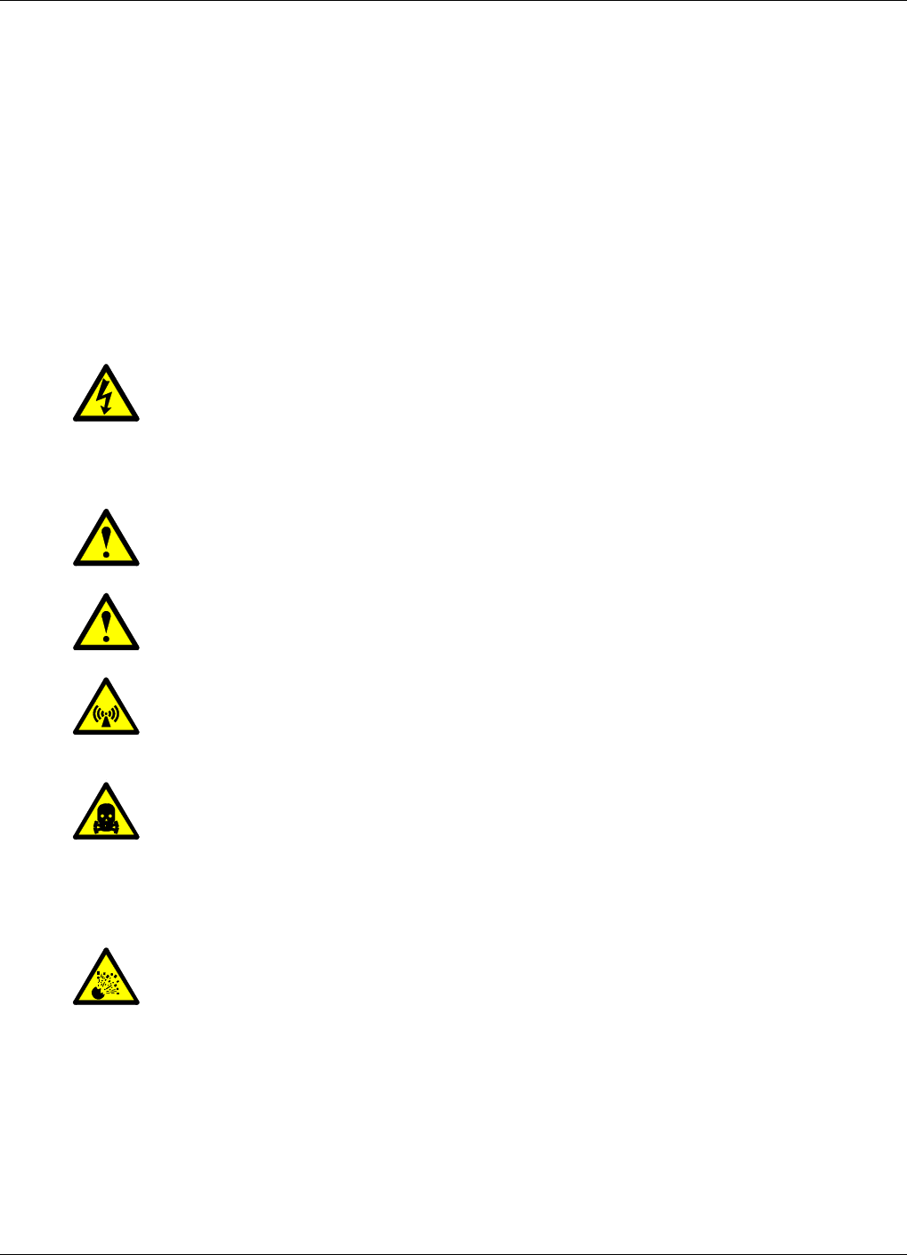
Figure 2-1. Allgon ALR Compact Repeater
ALLGON Systems AB ALR Compact Repeater Introduction
VD203 67/EN - User’s Manual Rev. P1D 2000-05 2 - 1

Repeater Types
The following repeater types are available:
•Band selective repeater with adjustable bandwidth
•Combined repeater
Band selective repeater with adjustable bandwidth
The band selective compact repeater has filters that can be set to various
bandwidths. This repeater type is used for analog or digital systems, such
as NMT, TACS/ETACS, AMPS, DAMPS and CDMA.
Combined repeater
Two separate band selective repeater units for different bandwidths or
systems can be combined in the same repeater chassis and be in operation
in parallel.
Introduction ALR Compact Repeater ALLGON Systems AB
2 - 2 Rev. P1D 2000-05 VD203 67/EN - User’s Manual

Using Repeaters
In areas where the radio signal propagation is poor repeaters can be used
to fill out those areas which are not covered by the base station.
The following scenarios are examples on this:
–Sports arenas
–Fair halls
–Large shopping centres
–Road and railway tunnels
–Indoors in buildings with metal or concrete walls
Other examples where repeaters can be used to increase the coverage are:
–Shaded areas
–Fringe coverage areas
In areas where the traffic intensity is low, it is not cost efficient to install
a base station. An Allgon repeater, which can be installed with a
minimum of investments, is a much better solution. You save installation
costs as well as operational costs.
Examples of using repeaters
Two examples are described in the following sections. An outdoor
example in a shaded valley and an indoor example in a sports arena.
ALLGON Systems AB ALR Compact Repeater Introduction
VD203 67/EN - User’s Manual Rev. P1D 2000-05 2 - 3
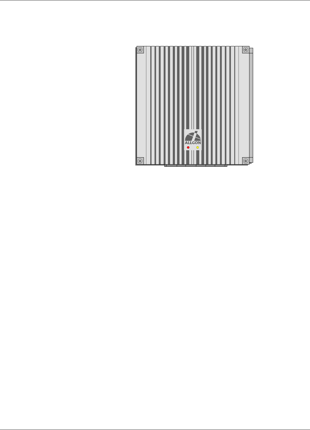
Shaded Area
A valley is shaded by hills. There is a base station 5 kilometers away, but
the lowest signal strength in the valley is less than –100dBm. A mast
used for other purposes is available for a repeater installation. The mast
height is 42 meter and it is located on a hill. The scenario is illustrated
in Figure 2-2.
The donor antenna of the repeater was mounted at the top of the mast
and the service antenna was mounted at the half mast. The antenna
isolation was measured to over 100dB. The repeater was set to max.
80dB gain.
Measured levels: Received signal level – 60.0 dBm
Donor antenna gain 15.0 dBi
Cable loss –5.0 dB
Repeater input level – 50.0 dBm
Adjusted repeater gain 70.0 dB
Repeater output level 20.0 dBm
Cable loss – 5.0 dB
Service antenna gain 8.0 dBi
Radiated output level 23.0 dBm
The measured result in the valley was better than –90dBm.
Donor antenna
Service antenna
Figure 2-2. Repeater coverage of shaded area
Introduction ALR Compact Repeater ALLGON Systems AB
2 - 4 Rev. P1D 2000-05 VD203 67/EN - User’s Manual
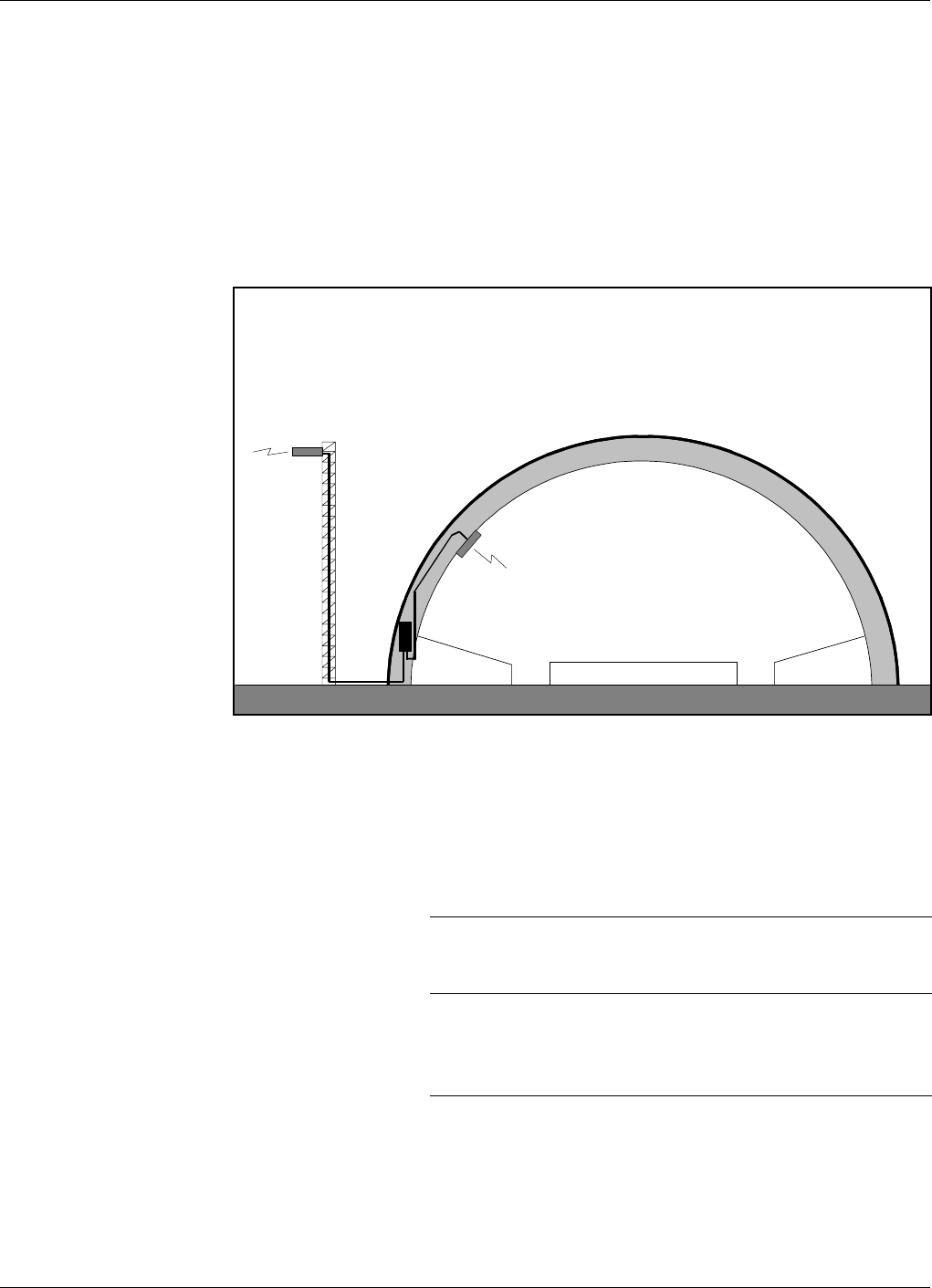
Sports Arena
A 2000 spectators sports arena with metallic roof had an indoor signal
strength too low to provide a fair service in most parts of the arena. The
nearest base station was 8 kilometers away and it was equipped with one
carrier only.
A donor antenna directed towards the base station was mounted on a
mast outside the building and a repeater was installed inside the building
with the service antenna on the arch vault. The scenario is illustrated in
Figure 2-3.
The antenna isolation was measured to over 85dB.
Measured levels: Received signal level – 80.0 dBm
Donor antenna gain 15.0 dBi
Cable loss –5.0 dB
Repeater input level – 70.0 dBm
Adjusted repeater gain 70.0 dB
Repeater output level 0.0 dBm
Cable loss – 2.0 dB
Service antenna gain 7.0 dBi
Radiated output level 5.0 dBm
The signal strength was fair for service in the entire arena.
Service antenna
Donor antenna
Figure 2-3. Repeater in sports arena
ALLGON Systems AB ALR Compact Repeater Introduction
VD203 67/EN - User’s Manual Rev. P1D 2000-05 2 - 5

3. Installation
Before installation, read carefully Chapter 1, Safety.
Siting the Repeater
Allgon repeaters are designed for outdoor usage. However, humidity and
temperature changes may have affect on the reliability. A preferable site
for the repeater is thus indoor, in a tempered and ventilated room.
Sunshine
If a repeater is placed outdoor and can be exposed to direct sunshine, it is
essential that the air can circulate around the repeater with no obstacle.
The operating temperature must not exceed +55°C. A shelter can be used
to shade the repeater from direct sunshine.
Shelter
Allgon repeaters are designed with a weather proof outdoor case that can
be mounted without any kind of shelter from rain, snow or hail.
If a repeater is to be opened on the site when raining, snowing, or hailing
there must be some kind of permanent or temporary shelter. This is
applicable to gentle rainfall, snowfall or hail. Limitations for very bad
weather is found in the next section.
Outdoor Installation and Service Limitations
Sited outdoors, the repeater must not be opened for installation or
service at bad weather, such as:
–Intense rainfall, snowfall or hail
–Storm or high wind
–Extremely low or high temperature
–High humidity of the air
ALLGON Systems AB ALR Compact Repeater Installation
VD203 67/EN - User’s Manual Rev. P1D 2000-05 3 - 1
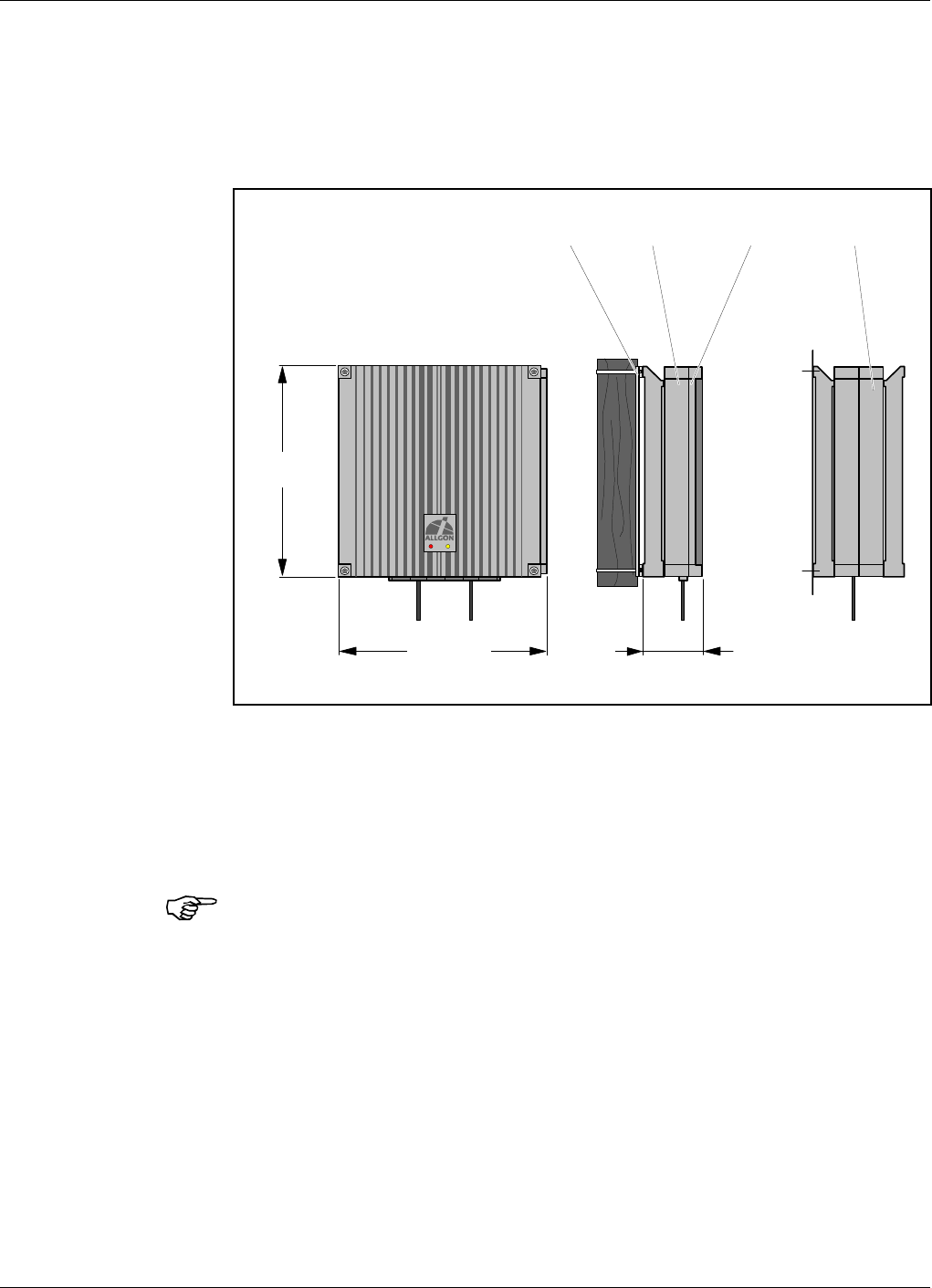
Dimensions and Weights
The dimensions of the repeater, including the mounting bracket, is shown
in Figure 3-1. The repeater chassis consists of two main parts, a cabinet
in which the circuitry is housed, and a cover, which can be either a thin
cover or a large cover (see the figure) depending on the configuration.
Approximately repeater weight
Repeater with thin cover ........................................................... 10 kg (22 lbs)
It is not recommended to remove the cover from the cabinet at the site.
However, if the cover, for some reason, has to be removed from the
cabinet, then disconnect the interconnection cables, close the cover,
remove the hinge shafts, and remove the cover.
385 (15.2")
385
(15.2")
110
(
4.3"
)
Mounting bracket Cabinet Thin cover Large cover
Figure 3-1. Repeater dimensions
Installation ALR Compact Repeater ALLGON Systems AB
3 - 2 Rev. P1D 2000-05 VD203 67/EN - User’s Manual
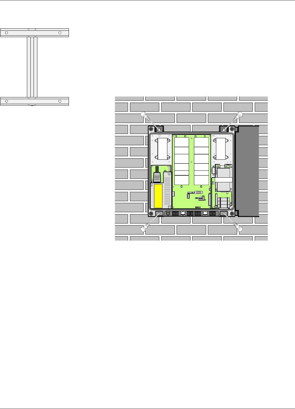
Mounting
The ALR repeater is easy to mount, either by anchoring the repeater in
the fixing holes, or using the an optional mounting bracket.
The mounting bracket is shown in the figure.
1. Mount the repeater.
Normally, the repeater is mounted on a wall, pole, or mast. These
mounting cases are shown below.
Figure 3-2 shows how to mount the repeater to a wall using four
fixing screws.
ANT
HI LO
ANT
LO HI
Figure 3-2. Attaching the repeater to a wall
ALLGON Systems AB ALR Compact Repeater Installation
VD203 67/EN - User’s Manual Rev. P1D 2000-05 3 - 3
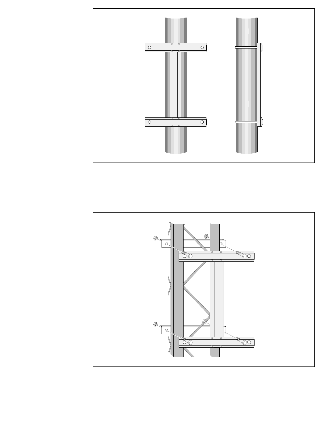
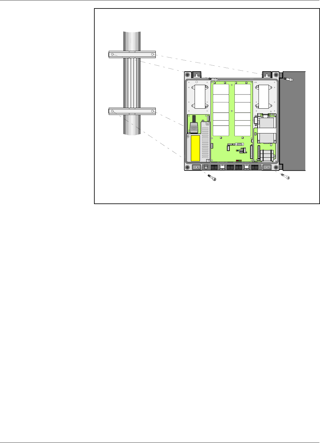
Figure 3-3 shows a bracket attachment to a pole using tensioning
devices.
Figure 3-4 shows a bracket attachment to a mast using the two
provided angle irons and four screws. The screw heads are slided
into the bracket profile.
Figure 3-3. Attaching the bracket to a pole
Figure 3-4. Attaching the bracket to a mast
Installation ALR Compact Repeater ALLGON Systems AB
3 - 4 Rev. P1D 2000-05 VD203 67/EN - User’s Manual
If the mounting bracket is used, then mount the repeater on the
bracket using four fixing screws (see Figure 3-5).
2. Mount the donor antenna directed towards the base station antenna.
3. Mount the service antenna directed towards the area to be covered by
the repeater.
ANT
HI LO
LO HI
ANT
Figure 3-5. Attaching the repeater to the bracket
ALLGON Systems AB ALR Compact Repeater Installation
VD203 67/EN - User’s Manual Rev. P1D 2000-05 3 - 5
Connection
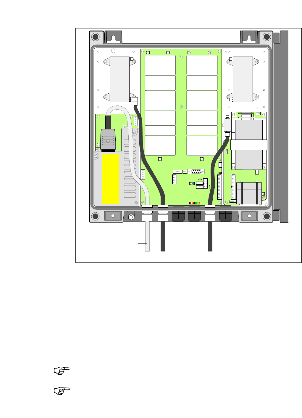
1. Connect the service antenna (MS) and donor antenna (BS) coaxial
cables (see Figure 3-6). N type female connectors are used in the
repeater.
The donor antenna (BS) is connected to the right in the cabinet.
The service antenna (MS) is connected to the left in cabinet.
2. Make sure the mains connector is connected to the power supply
unit, PSM.
For repeaters supplied from the mains, the mains outlet must be
grounded. Connect the yellow/green cable part to ground.
Both the mains plugs of repeaters equipped with two power supply
units must be connected to outlets supplied from the same fuse.
ANT
HI LO
ANT
LO HI
MS BS
Mains
Figure 3-6. MS and BS antenna connections
Installation ALR Compact Repeater ALLGON Systems AB
3 - 6 Rev. P1D 2000-05 VD203 67/EN - User’s Manual
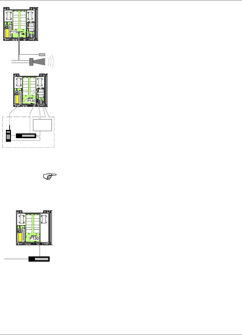
3. Connect external alarm sensors (burglary, fire, etc.) and other
external alarm equipment (optical or acoustic signal, etc.), if any.
Cables for this installation is taken through a free strain relief
bushing on the bottom of the repeater, in the same way as the mains
cable and the antenna cables.
External alarm is connected to the P119 alarm port located in the
centra in the cabinet (see Figure 3-7 on page 3-9). Use a 7 pole male
connector.
The P119 port is described on page 3-11.
This is a schematic figure of
the various RCC parts.
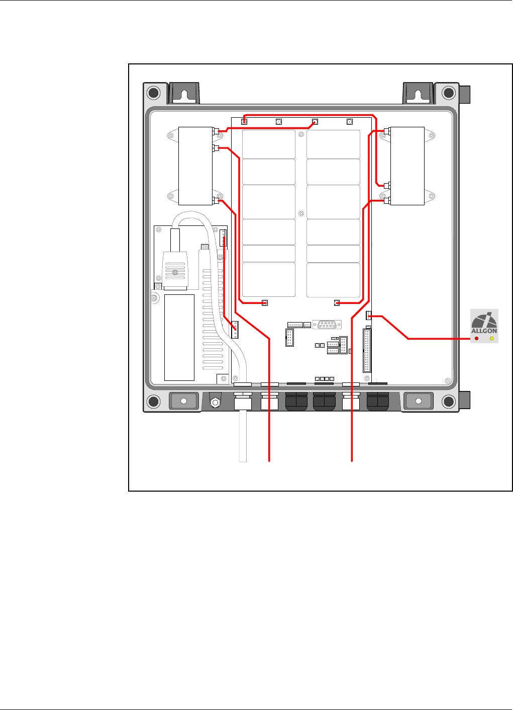
4. Connect the internal phone/modem unit for remote control of the
repeater, if any.
The modem and a power backup unit are integrated in an RCC,
Remote Control unit for Compact repeater, which is mounted to the
right inside the cabinet and connencted to the P130 port located to
the right in the cabinet (see Figure 3-7 on page 3-9).
The RCC is also powered by the P130 port.
The mobile phone antenna is connected to the BS antenna via an
uplink combiner located at the RCC unit to the right in the cabinet,
provided that the phone and the repeater operate in the same system.
Pin 1 and 2 of the P130 port are interconnected with a jumper if no
RCC is used. This jumper must be removed before plugging the RCC
connector to the P130 port.
If the RCC is removed, the jumper between pin 1 and 2 on the P130
port must be reconnected. Otherwise, a part of the circuitry will have
no voltage supply. Do not connect the jumper to another position than
between pin 1 and 2 on the P130 port.
The P130 port is described on page 3-12.
5. Connect a telephone line for remote control of the repeater, if any.
The telephone line is connected to a modem, which is connected to
the P130 modem port on the repeater.
The P130 port is described on page 3-12.
Use a free strain relief bushing at the bottom of the repeater for the
external telephone line cable.
ANT
HI LO
ANT
LO HI
External
alarm sensors
ANT
HI LO
ANT
LO HI
RCC
Modem
Battery
Power supply
ANT
HI LO
ANT
LO HI
Telephone line
Modem
ALLGON Systems AB ALR Compact Repeater Installation
VD203 67/EN - User’s Manual Rev. P1D 2000-05 3 - 7
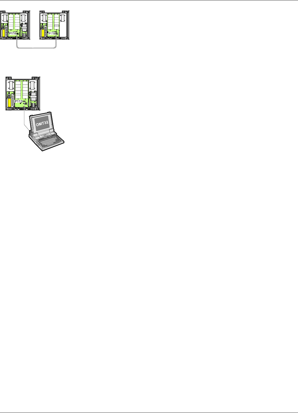
6. Connect the Repeater to Repeater Link cable, if this optional feature
is to be used. The R2R net cable is connected to the P118 or P124
Repeater to Repeater Link ports to the right in the repeater.
The P118 and P124 Repeater to Repeater Link port s are described
on page 3-10 and page 3-12.
Free strain relief bushings at the bottom of the repeaters are used for
the external net cable.
7. Connect a PC for controlling the repeater. A COM port on the PC is
connected to the P112 PC port located to the right in the cabinet (see
Figure 3-7 on page 3-9). Use a standard RS-232 serial cable.
Port P112 is described on page 3-10.
Now, you can commission the repeater as described in Chapter 4.
ANT
HI LO
ANT
LO HI ANT
HI LO
ANT
LO HI
ANT
HI LO
ANT
LO HI
Installation ALR Compact Repeater ALLGON Systems AB
3 - 8 Rev. P1D 2000-05 VD203 67/EN - User’s Manual
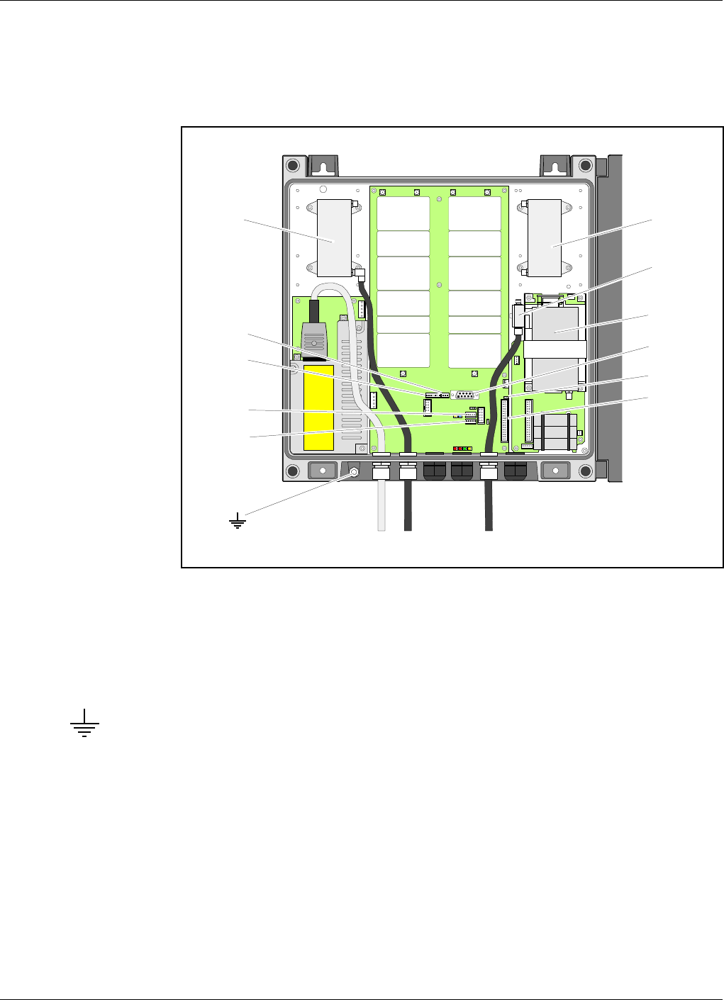
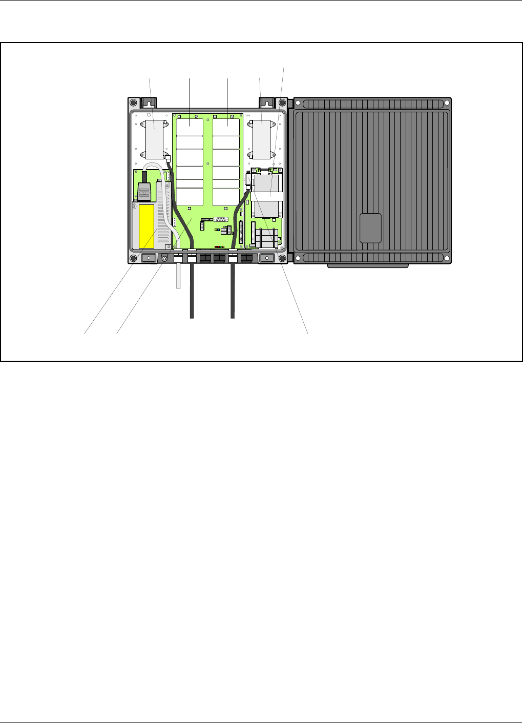
Connection Ports and Station Ground
Connectors involved in the installation are described below.
Station ground is also detailed below.
Station Ground
There is a ground screw (M8) on the repeater that is intended for station
ground (see Figure 3-7). This screw must be used only for station
grounding.
ANT
HI LO
ANT
LO HI
MS BS
DPX
MS
CMB
UL
P124
RCC
P118
P120
P119
DPX
BS
P130
P112
P113
Figure 3-7. Connection ports and station ground
ALLGON Systems AB ALR Compact Repeater Installation
VD203 67/EN - User’s Manual Rev. P1D 2000-05 3 - 9

P112 PC Port
PC port P112 is a RS-232 port used for local PC communication.
P112 is a 9 pole D-sub female connector located to the right in the cabinet
(see Figure 3-7).
Connector pinning
Pin 1 Not used
Pin 2 Data from repeater to OMT32
Pin 3 Data from OMT32 to repeater
Pin 4 DTR from OMT32 to repeater
Pin 5 GND
Pin 6 DSR from repeater to OMT32
Pin 7 RTS from OMT32 to repeater
Pin 8 CTS from repeater to OMT32
Pin 9 Not used
P113 Parking Device
P113 is a parking device for a jumper used for the P130 port. The jumper
is used to interconnect pin 1 and pin 2 of the P130 port when there is no
RCC remote communication control unit connected to the repeater.
When an RCC unit is connected to the repeater, then the jumper can be
placed in P113.
P113 is an unconnected 2 pole male connector located to the right in the
cabinet, adjacent to the P130 connector (see Figure 3-7).
P118 Repeater to Repeater Link Port
P118 is used for the Repeater to Repeater Link feature (R2R net).
P118 is a 5 pole male connector located to the right in the cabinet,
adjacent to the P124 connector (see Figure 3-7).
The P118 and P124 ports are identical an connected in series. One of the
connectors are intended to be used from the previous repeater in the net
chain, and the other connetor to the next repeater in the net chain.
Either of P118 or P124 can be used for the first and the last repeater in
the net chain.
6
5
9
1
15
Installation ALR Compact Repeater ALLGON Systems AB
3 - 10 Rev. P1D 2000-05 VD203 67/EN - User’s Manual

P119 Alarm Port
Alarm port P119 is used for external alarm sensors and alarm equipment.
P119 is a 7 pole male connector located in the center of the cabinet (see
Figure 3-7).
The port has four alarm inputs, EAL1 - EAL4.
The four alarm inputs
The inputs are low-level inputs with common ground (AIC).
Use insulated switch or relay to initiate alarms (open switches in normal
operating mode, closed switches cause alarm).
The alarm switch connection can be toggled between being active open or
active closed. This is further described in the AR Repeaters and OMT32,
User’s Manual.
The alarm input voltage ratings, related to ground, are:
Vinmax = 5.5V
Vinmin =–0.5V
Connector pinning
Pin 1 AIC Ground
Pin 2 AIC Ground
Pin 3 AI1 External alarm input 1 – EAL1
Pin 4 AI2 External alarm input 2 – EAL2
Pin 5 AI3 External alarm input 3 – EAL3
Pin 6 AI4 External alarm input 4 – EAL4*
Pin 7 Not used
*EAL4 can also be configured as door alarm with settable alarm level, see
P120 below.
17
ALLGON Systems AB ALR Compact Repeater Installation
VD203 67/EN - User’s Manual Rev. P1D 2000-05 3 - 11
P120 Door Switch
P120 is used for repeater door alarm. An internal door switch is
connected to this port to activate door alarms.
P120 is a 3-pole male connector located in the center of the cabinet,
adjacent to the P119 alarm connector (see Figure 3-7).
The alarm level for this input is always Warning w ceasing.
This alarm input is separated from the alarm inputs in the P119 alarm
connector. The EAL4 in the P119 alarm port (pin 6) can also be
configured as door alarm input with settable alarm level.
The door switch alarm is activated 30 seconds after the door switch has
been activated.
Connector pinning
Pin 1 Ground
Pin 2 Alarm input
Pin 3 Power (5V, 10mA for the door alarm circuitry)
P124 Repeater to Repeater Link Port
P124 is used for the Repeater to Repeater Link feature (R2R net).
P124 is a 5 pole male connector located to the right in the cabinet,
adjacent to the P118 connector (see Figure 3-7).
The usage of P118 and P124 is described on page 3-10.
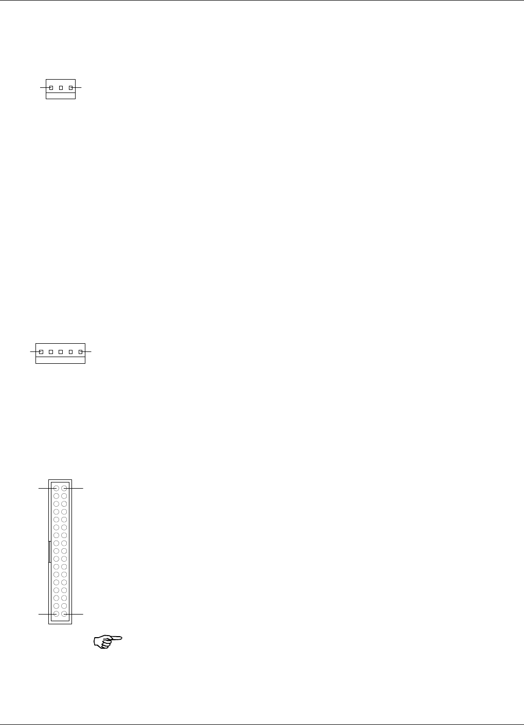
P130 RCC Port
The P130 RCC port is used for connecting an RCC mobile phone/modem
remote control unit.
P130 is a 34 pole 2 line male connector located to the right in the cabinet
(see Figure 3-7).
The P130 connector contains modem/telephone line connection, RCC
power supply, etc.
If there is no RCC remote communication control unit connected to the
P130 port, then pin 1 and pin 2 must be interconnected with a jumper
(see P113 on page 3-10).
Pin 1 and 2 of the P130 port MUST ALWAYS be interconnected to provide
voltage supply to a particular part of the repeater circuitry.
13
15
12
33 34
Installation ALR Compact Repeater ALLGON Systems AB
3 - 12 Rev. P1D 2000-05 VD203 67/EN - User’s Manual
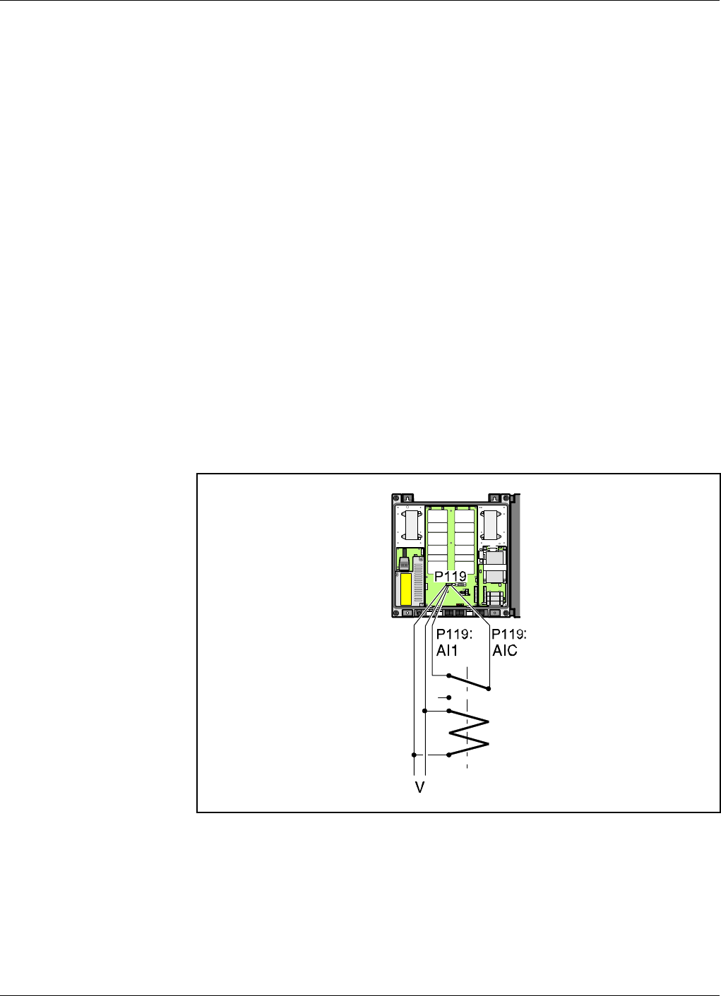
Mains Breakdown Relay
To be able to distinguish PSM faults from power failure, a mains
breakdown relay must be used on the repeater mains supply.
The mains breakdown relay is not included in the repeater. So, it has to
be mounted outside the repeater chassis. The relay intended for this
purpose must fulfil the following specifications:
Relay specifications
Closing time: max. 30 milliseconds
Insulation coil/contact: min. 4KV
Mains connected relay must be in compliance with valid local regulations.
Connection
•Connect a normally closed relay contact to pin AI1 and AIC on the
P119 alarm connector (closed contact at no current). Alarm is initiated
by short circuiting the AI1 and AIC inputs as shown in Figure 3-8. The
P119 alarm connector is detailed on page 3-11.
•Connect the relay coil. It must be supplied from the same fuse as the
repeater.
•After commissioning, set the mains breakdown feature as described in
the AR Repeaters and OMT32, User’s Manual.
ANT
HI LO
ANT
LO HI
Figure 3-8. Mains breakdown relay connection
ALLGON Systems AB ALR Compact Repeater Installation
VD203 67/EN - User’s Manual Rev. P1D 2000-05 3 - 13

4. Commissioning
Read carefully Chapter 1 Safety before commissioning the repeater.
Check all connections made during the installation. Also, ensure that
both the mains plugs for repeaters equipped with two power supply units
are connected to outlets supplied from the same fuse.
To fulfill the IP65 weather protective requirements, ensure that the cable
strain relief bushings are properly tightened. Also, ensure that the
gaskets at the cable inlets and on the cabinet are properly fitted and not
damaged.
When the installation is checked, commission the repeater as described
below.
ALLGON Systems AB ALR Compact Repeater Commissioning
VD203 67/EN - User’s Manual Rev. P1D 2000-05 4 - 1

Starting the Repeater
1. Connect the repeater to the mains.
2. Check the four LEDs downmost in the repeater (see Figure 4-1).
A correct power-up is indicated as follows:
PWR
Yellow LED which is lit with a steady light after the mains is
switched on. Indicates present power.
BOOT
Red LED that is lit with a steady light when the system boots, i.e. for
10 - 15 seconds after the mains is switched on. Then, it flashes for
the next 5 - 10 seconds. After that, if no error is detected, the LED
is off.
FAULT
Red LED that flashes 15 - 20 seconds after the mains is switched on.
Then, it flashes for less serious alarms (ERROR) and is lit with a
steady light for fatal alarms (CRITICAL).
OPER
Green LED that lights up approx. 15 seconds after the mains is
switched on. It shows, with a steady light, that the repeater is ready
for operation.
External indicators on the repeater front
Yellow
Operation LED which lights up approx. 15 seconds after the mains is
switched on. At steady light the repeater is ready for operation.
Red
Alarm LED which indicates ERROR alarms with flashing light and
CRITICAL alarms with steady light.
When the indicators show operational mode, the repeater can be
configured for operation by using an OMT32/PC. This is further detailed
in the AR Repeaters and OMT32, User’s Manual.
Commissioning ALR Compact Repeater ALLGON Systems AB
4 - 2 Rev. P1D 2000-05 VD203 67/EN - User’s Manual
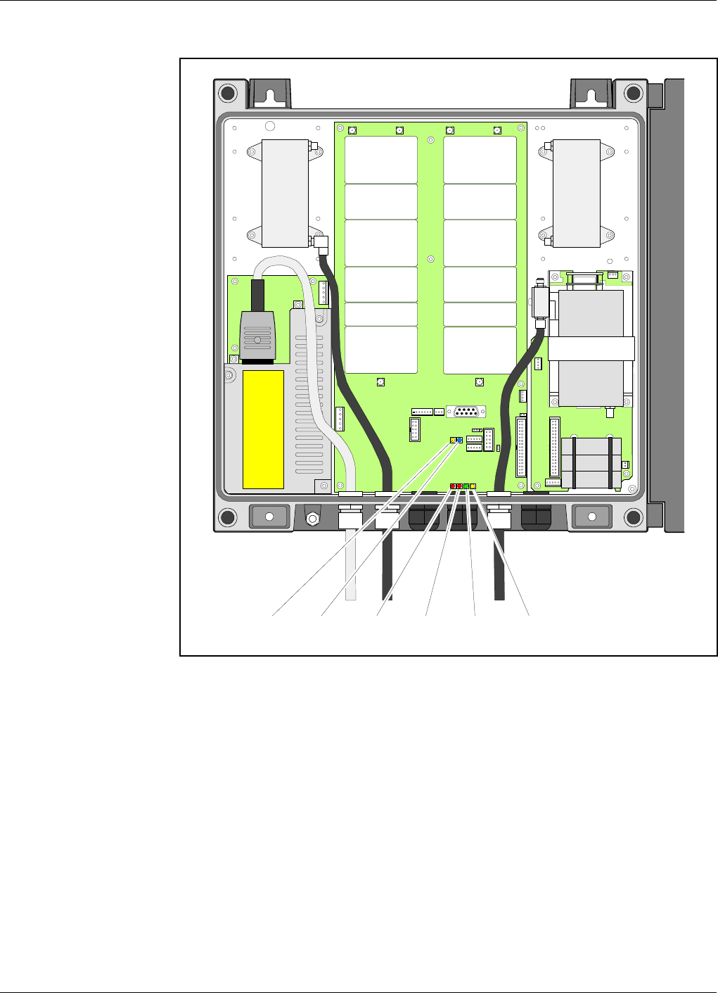
Indicators
Figure 4-1 shows the repeater indicators . There are also two external
indicators on the repeater front cover.
Repeater to Repeater Link
indicators
The two upper indicators, R2R and DATA, indicates the following R2R
status:
R2R
Green LED that indicates, with a flashing light, that data is transferred
and that the repeater currently is a Control Station. A steady light
indicates that the repeater is not currently a Control Station, or there is
no more repeater in the net. Only one repeater in an R2R net can show a
flashing green LED at the same time.
DATA
Blue LED that indicates data transmission in the net.
ANT
HI LO
ANT
LO HI
PWR
BOOT
FAULT OPERR2R DATA
Figure 4-1. Indicators in the cabinet
ALLGON Systems AB ALR Compact Repeater Commissioning
VD203 67/EN - User’s Manual Rev. P1D 2000-05 4 - 3

Repeater Configuration
The repeater is now ready to be configured in accordance with the site
conditions and system performance requirements. Pay especial attention
to the antenna isolation described in the AR Repeaters and OMT32,
User’s Manual.
Commissioning ALR Compact Repeater ALLGON Systems AB
4 - 4 Rev. P1D 2000-05 VD203 67/EN - User’s Manual

5. Functional Description and Design
Allgon repeaters work as bi-directional on-frequency amplifiers.
A repeater receives, amplifies, and retransmits signals downlink and
uplink simultaneously, i.e. from the base station via the repeater to the
mobile stations and from the mobile stations via the repeater to the base
station.
The repeater is connected to a BS antenna, directed towards the base
station, and to a MS antenna directed towards the area to be covered.
These antennas are connected to the repeater with N type male
connectors.
To prevent instability due to poor antenna isolation, a built-in antenna
isolation supervision feature reduces the gain level automatically when
poor antenna isolation is detected.
The Allgon repeaters are controlled by powerful microprocessors.
Alarm and operational LEDs are visible on the repeater front.
The repeater works with convection cooling without fan.
Operational parameters such as gain, power levels, etc. are set using a
desktop or notebook and the Allgon OMT32, which communicate, locally
or remotely via modem, with the repeater. Remote operation is
performed using a telephone line or a built-in mobile phone equipped with
a data interface.
ALLGON Systems AB ALR Compact Repeater Functional Description
VD203 67/EN - User’s Manual Rev. P1D 2000-05 5 - 1

Repeater Design
The repeater is housed in a cast aluminium chassis that is waterproof,
class NEMA4/IP65, for outdoor use. The chassis has a design suited for
outdoor use as well as indoor use.
The chassis consists of a cabinet and a cover joined with hinges. The
cabinet contains the repeater circuitry. The cover can either be a thin
cover or a large cover. The latter consists of another cabinet which can
be used as an empty cover or be equipped as an independent repeater unit.
The cover has two external LEDs for operation and alarm indication.
The cabinet as well as a large cover can be equipped for band selective
operation with adjustable bandwidth. A combined repeater can be
equipped for different bandwidths or different systems.
Both the uplink and downlink circuitry is built up on a single BSC board
inside the repeater. The various amplifiers and RF modules are
individually shielded by metal covers.
The BSC band selective compact repeater board
The band selective compact repeater board can handle one wide band
repeater channel, uplink and downlink. The band width is adjustable.
Other units
In addition to the BSC repeater board, the repeater contains:
•DPX Duplex filter, located on the upper part of the repeater.
•CMB Combiner unit, located on the RCC unit in repeaters with an RCC
unit that works in the same system as the repeater.
•RCC unit (optional), see Chapter 6, Optionals. This is located to the
right in the cabinet.
•PSM Power Supply unit, located to the left in the cabinet, and in the
cover, if equipped.
•The repeater is equipped with an R2R, Repeater to Repeater Link
feature that can be used between different repeaters or between the
cabinet repeater unit and the cover repeater unit.
Functional Description ALR Compact Repeater ALLGON Systems AB
5 - 2 Rev. P1D 2000-05 VD203 67/EN - User’s Manual
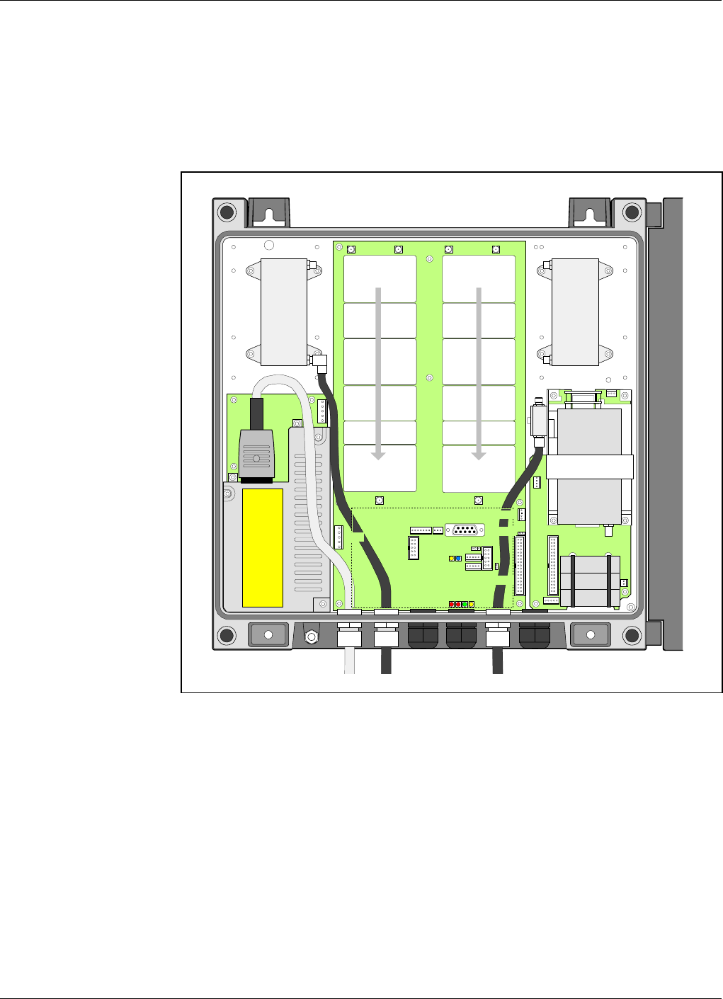
Single Band Repeater Units
A cabinet (the left part in Figure 5-1) for a band selective repeater is
equipped with a BSC board including the downlink and uplink circuitry.
The described cabinet is equipped for bi-directional band selective
operation and RCC remote control.
The BSC board is used for band selective systems with an adjustable
bandwidth within 890 – 915MHz uplink and 935 – 960MHz downlink.
Main units: BSC Band Selective Compact board, adjustable bandwidth
CMB Combiner unit, uplink, for RCC antenna
DPX Duplex filter
PSM Power Supply unit
RCC Repeater Communication Control unit
ANT
HI LO
ANT
LO HI
DPX
MS DPX
BS
PSM
RCC
BSC
MS
Mobile station
antenna
BS
Base station
antenna
Downlink
circuitry Uplink
circuitry
CMB Uplink
Figure 5-1. Single band repeater units
ALLGON Systems AB ALR Compact Repeater Functional Description
VD203 67/EN - User’s Manual Rev. P1D 2000-05 5 - 3
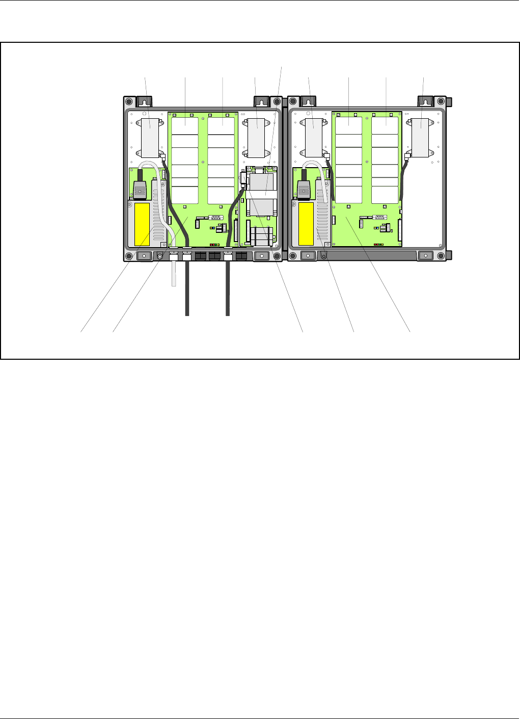
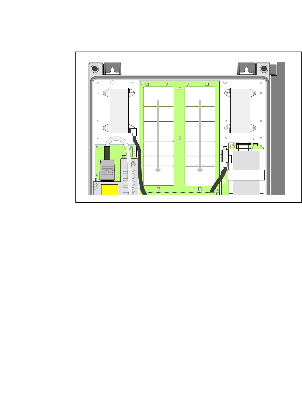
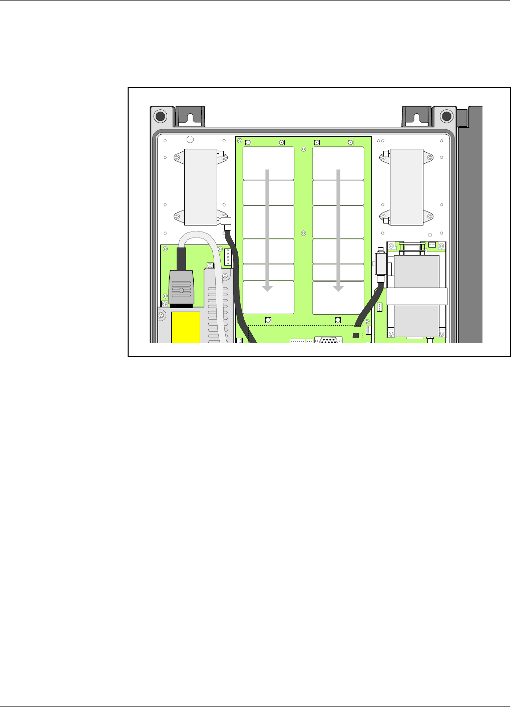
Dual Band Repeater Units
Figure 5-2 shows an example of a combined band selective repeater for
dual bands. The repeater part in the cabinet is equipped with an RCC
unit that is used for communication between both the repeater parts via
the R2R feature. This feature can also be used to communicate with other
repeaters, ALR Compact repeaters as well as standard AR repeaters.
Both the BSC boards are used for band selective systems with an
adjustable bandwidth within 890 – 915MHz uplink and 935 – 960MHz
downlink.
If both the repeater parts are linked to the same base station, then the BS
antenna cables are connected to the same antenna via a combiner unit
(CMB). Otherwise separate antenna cabels are used from the repeater to
the antennas.
If both the repeaters cover the same area, then the same thing is
applicable to the MS antenna cables.
Main units: BSC Band Selective Compact board, adjustable bandwidth
CMB Combiner unit, uplink, for RCC antenna
DPX Duplex filter
PSM1 Power Supply unit 1 (in the cabinet)
PSM2 Power Supply unit 2 (in the cover)
RCC Repeater Communication Control unit
ANT
HI LO
ANT
LO HI ANT
HI LO
ANT
LO HI
DPX
MS DPX
BS
PSM1
RCC
BSC
DPX
MS DPX
BS
BSCPSM2
MS
Mobile station
antenna
BS
Base station
antenna
Downlink
circuitry Uplink
circuitry
CMB Uplink
Downlink
circuitry Uplink
circuitry
Figure 5-2. Dual band repeater units
Functional Description ALR Compact Repeater ALLGON Systems AB
5 - 4 Rev. P1D 2000-05 VD203 67/EN - User’s Manual

Block Diagram
A band selective compact repeater block diagram is found on page 5-6.
The signal path and some of the most important features are described
after the block diagram.
Downlink Signal Path
The downlink signal path, i.e. from the base station through the repeater
to the mobile station, is described after the block diagram.
Uplink Signal Path
The uplink signal path, i.e. from the mobile station through the repeater
to the base station, is identical to the downlink path the other way round.
Only some levels and component values differ.
ALLGON Systems AB ALR Compact Repeater Functional Description
VD203 67/EN - User’s Manual Rev. P1D 2000-05 5 - 5
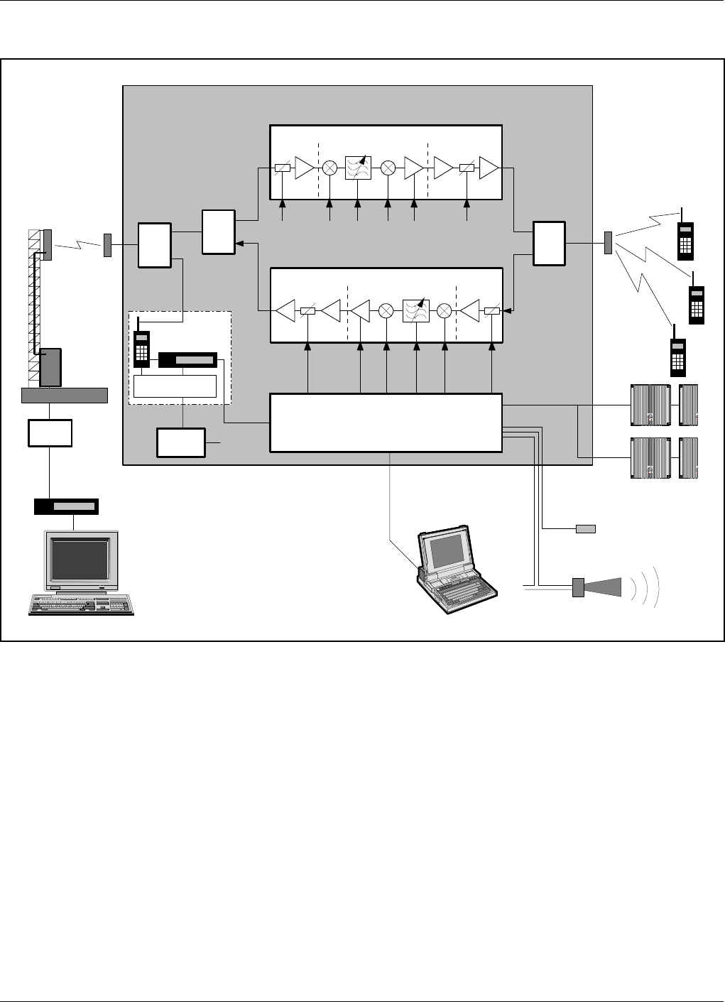
Band Selective Compact Repeater Block Diagram
Figure 5-3 shows a block diagram of the band selective compact repeater.
This diagram is applicable to repeaters for e.g. NMT, TACS/ETACS and
AMPS/DAMPS systems.
Downlink signal path
The signal from the base station is received via the repeater BS antenna
and is forwarded through a combiner (CMB) to the ANT input of a duplex
filter (DPX). The signal from the LO output of the duplex filter is, via
the P126 port, fed to the BSC board. On the BSC board, the signal is
amplified in a low noise amplifier (LNA) and is then entered the band
selective amplifier circuitry.
The first mixer stage in the BSC amplifier, which is controlled by a
synthesizer, converts the received frequency down to the IF frequency.
The signal is then filtered by a SAW bandpass filter and, not shown in the
RCC
BSC - UL
PA LNA
P121 P122
BSC - DL PA
LNA
P126 P128
P130
P112 P119
P130
DPX
MS
P118
BSC - CU
P124
CMB
BS
ANT HI
LO HI
LO ANT
DPX
BS
MSC PSM
BAND SELECTIVE COMPACT REPEATER
BS
antenna
Base station
Telephone line
Modem
Modem
Battery
External alarm sensors
MS
antenna
Figure 5-3. Block diagram
Functional Description ALR Compact Repeater ALLGON Systems AB
5 - 6 Rev. P1D 2000-05 VD203 67/EN - User’s Manual

figure, amplified before it is fed to the second mixer stage, controlled by
the same synthesizer as the previous one, for converting back to the
original frequency.
The SAW filter is adjustable and can be software changed from within
OMT32 (or OMS) to cover various band widths.
The following power amplifier (PA) is controlled by the Control Unit
(CU). The output gain can be reduced to avoid instability due to poor
antenna isolation.
A detector in the PA stage measures continuously the output level. The
signal from this detector is used by the automatic gain control, AGC, to
supervise and, if necessary, reduce the output power to keep it under a
maximum level. The AGC gain control affects all the amplification stages.
The output signal from the BSC board is taken from the P128 port and it
is fed to the HI port of a duplex filter (DPX). The output signal from the
ANT port of the duplex filter is fed to the repeater MS antenna.
RCC
The optional RCC Remote Communication Control unit is located inside
the repeater, see Figure 5-1 on page 5-3.
Communication with the base station is performed by means of a built-in
mobile feature that has the antenna connected to the BS combiner
(CMB). Data is transferred between the repeater CU and the built-in
mobile feature via the P130 port.
The RCC unit is powered via the P130 port and the unit has a battery
with capacity to send a number of alarms if a mains power failure occurs.
R2R
The Repeater to Repeater Link feature makes it possible to communicate
with a number of repeaters via one RCC unit in one of the repeaters in an
R2R net. Several RCC units can be used in the same net.
The repeaters in the R2R net are connected to the P118 port and to the
P124 port.
The R2R feature is further described on page 5-18.
ALLGON Systems AB ALR Compact Repeater Functional Description
VD203 67/EN - User’s Manual Rev. P1D 2000-05 5 - 7

Alarm
Alarm signals from external sensors are received via the P119 alarm port.
The software on the BSC board is able to activate acoustic or visual alarm
or direct the alarm to the P130 PCC port to be forwarded, via the RCC
unit (or modem and telephone line) to OMT32 (or OMS) located in an
operation and maintenance central.
Alarms can be configured from OMT32 (or from OMS).
Repeater Setup
The repeater parameters can be set locally by means of a desktop or
notebook loaded with the OMT32 software (or the OMS software). The
PC or notebook is connected to the repeater via the P112 PC port.
The repeater parameters can also be set remotely by means of an RCC
Remote Communication Control unit (or via a telephone line and a
modem) connected to the repeater via the P130 PCC port.
Functional Description ALR Compact Repeater ALLGON Systems AB
5 - 8 Rev. P1D 2000-05 VD203 67/EN - User’s Manual
Board and Unit Descriptions
Cabling between boards and units is found on page 5-16 (with RCC unit)
and page 5-16 (without RCC unit).
CMB - Combiner
There is one BS combiner in a single band repeater equipped with an
RCC Remote Communication Control unit.
This unit combines the uplink/downlink signal from the BS antenna with
the RCC mobile antenna.
Connection
To the right in the cabinet CMB/BS
Port Connected to
IN? MS antenna.
OUT1? ANT on the DPX/BS duplex filter.
OUT2? RCC mobile antenna.
DPX - Duplex Filter
The DPX duplex filters on the BS and MS sides are identical.
Connection
To the left in the cabinet DPX/MS
Port Connected to
ANT MS antenna port.
HI P128 on the BSC board (downlink PA power amplifier).
LO P122 on the BSC board (uplink LNA low noise amplifier).
To the right in the cabinet DPX/BS
Port Connected to
ANT OUT1 on the CMB/BS combiner (BS antenna signal).
HI P121 on the BSC board (uplink PA power amplifier).
LO P126 on the BSC board (downlink LNA low noise amplifier).
ALLGON Systems AB ALR Compact Repeater Functional Description
VD203 67/EN - User’s Manual Rev. P1D 2000-05 5 - 9
BSC Band Selective Compact Board
The compact band selective orepeater is built up mainly on a single BSC
board that contains all the amplification circuitry for uplink and downlink
and the CU, Control Unit, circuitry. This board contains also all the ports
for alarm, local control, remot control, etc.
Figure 5-4 shows the BSC board in the compact repeater.
The left upper part of the BSC board contains the downlink circuitry. The
downlink signal path starts from port P126, is fed to the LNA, Low Noise
Amplifier, then it passes a number of amplifiers, and is finally fed to the
PA, Power Amplifier before it is fed, via port P128, to the DPX/MS
HI port to be forwarded to the MS antenna.
The right upper part of the BSC board contains the corresponding
circuitry for the uplink signal path, from port P122, via port P121,
DPX/BS HI port and to the BS antenna.
ANT
HI LO
ANT
LO HI
DPX
MS DPX
BS
P126 P127 P122 P123
P128 P121
P131
P119 P120 P112
P118
P124
P118
CU
LNA/DL
PA/DL
LNA/UL
PA/UL
P130
P111
P115 P113
Figure 5-4. BSC, Band Selective Compact board
Functional Description ALR Compact Repeater ALLGON Systems AB
5 - 10 Rev. P1D 2000-05 VD203 67/EN - User’s Manual

CU Control Unit
The CU unit is the central part of the repeater, located in the lower part
of the BSC board (inside the dotted line in Figure 5-4).
The CU unit contains a microprocessor, main memory, flash memory for
the CU software, EEPROM memory for parameters, memory for the event
log and statistics, a REFO reference oscillator, ports for local and remote
communication, battery powered real-time clock, etc.
The CU unit supervises and controls operational parameters such as gain
control, etc. The CU takes also care of alarms and the event log,
password, logon, and many other tasks.
The CU is also a control interface when communicating with an OMT32
or OMS, locally or remotely.
The CU software can be downloaded from OMT32 or OMS either locally
or remotely.
The real-time clock in the CU unit is used for alarm and for the event log.
CU software
The CU unit on the BSC board can be run with the SAXXX XX/X CU
software. The unit can store two versions of CU software, located in
segment 1 and segment 2 of the flash memory as Application 1 and
Application 2. The repeater will boot on that software which is set as
Primary (a description of the Primary application is found in the
AR Repeaters and OMT32, User’s Manual.
The compatibility between the BSC board and CU software is detailed in
the next section.
Caution
A lithium battery is permanently mounted on the BSC board. Due to the
risk of explosion, this battery must only be removed from the board by an
authorized service technician.
ALLGON Systems AB ALR Compact Repeater Functional Description
VD203 67/EN - User’s Manual Rev. P1D 2000-05 5 - 11

Connection and connector types
The BSC board is also a distribution board with most of the repeater
ports. The connector types are chosen to prevent unintentional mixing up.
Port Connected to Connector type
P111 LED board in the cover. 4 pole 1 line male.
P112 PC (serial RS-232). 9 pole D-sub female.
P113 Not connected (jumper parking device). 2 pole 1 line male.
P115 PSM - Power Supply unit 5 pole 1 line male.
P118 R2R connection to P118 or P124 in the
next compact repeater, or to the R2R
connector board in a standard AR repeater.
5 pole 1 line male.
P119 External alarm sensors and alarm
equipment.
7 pole 1 line male.
P120 Door switch (internal alarm). 3 pole 1 line male.
P121 HI on DPX/BS duplex filter (uplink output
signal).
Coaxial
P122 LO on DPX/MS duplex filter (uplink input
signal).
Coaxial
P123 P122 on the cover BSC board (expansion
output), if equipped.
Coaxial
P124 R2R connection to P118 or P124 in the
next compact repeater, or to the R2R
connector board in a standard AR repeater.
5 pole 1 line male.
P126 LO on DPX/BS duplex filter (downlink
input signal).
Coaxial
P127 P126 on the cover BSC board (expansion
output), if equipped.
Coaxial
P128 HI on DPX/MS duplex filter (downlink
output signal).
Coaxial
P130*RCC Remote Communication Control unit,
or modem for traditional telephone line.
34 pole 2 line male.
*Pin 1 and 2 of the P130 connector must be interconnected with a jumper
if the connector is not used.
Testpoints
There are no testpoints intended for field maintenance or calibration.
Availalbe testpoints on the board are used for factory calibration only.
Functional Description ALR Compact Repeater ALLGON Systems AB
5 - 12 Rev. P1D 2000-05 VD203 67/EN - User’s Manual
LNA - Low Noise Amplifier
Two LNA, Low Noise Amplifiers, are located uppermost on the BSC board
in shielded covers. LNA/DL (downlink) is located to the left and LNA/UL
(uplink) to the right.
Received signals from the duplex filters are fed to the LNA input
connectors P122 (uplink) and P126 (downlink). The output signals from
the LNA amplifiers are fed to the next amplifier stages for uplink and
downlink on the BSC board.
The P123 and P127 ports are expansion outputs used as inputs for an
additional repeater in the cover, if the repeater has an equipped cover
that works in the same system. The gain to this connector is +2dB.
Connection
The P122, P123, P126 and P127 ports are connected as shown on
page 5-12.
ANT
HI LO
ANT
LO HI
DPX
MS DPX
BS
P126 P127 P122 P123
P128 P121
LNA/DL
PA/DL
LNA/UL
PA/UL
P111
Figure 5-5. LNA, Low Noise Amplifiers
ALLGON Systems AB ALR Compact Repeater Functional Description
VD203 67/EN - User’s Manual Rev. P1D 2000-05 5 - 13
PA - Power Amplifier
Two PA, Power Amplifier, are located in the middle of the BSC board in
shielded covers. PA/DL (downlink) is located to the left and PA/UL
(uplink) to the right.
The final power amplification for the downlink signal is performed in the
PA/DL stage. Then the signal is fed via the P128 port to the HI port of
the DPX/MS duplex filter and from this filter to the MS antenna.
The uplink final power amplification is performed in the same way and is
fed to the BS antenna via the P121 port and the HI port of the DPX/BS
duplex filter.
Connection
The P121 and P128 ports are connected as shown on page 5-12.
ANT
HI LO
ANT
LO HI
DPX
MS DPX
BS
P126 P127 P122 P123
P128 P121
P119 P120 P112
LNA/DL
PA/DL
LNA/UL
PA/UL
P111
P113
Figure 5-6. PA, Power Amplifiers
Functional Description ALR Compact Repeater ALLGON Systems AB
5 - 14 Rev. P1D 2000-05 VD203 67/EN - User’s Manual

Repeater CU Software and Hardware Compatibility
There are different versions of repeater CU software, which can be
combined with boards of various revisions. These have unique part
numbers and revision information. Below, you will find a table of
repeater software currently available in combination with BSC board
revisions.
CU Software
Part #
Software
Revision
Compatible
with
BSC board
Comments
SA??? ??/? R?? K???/? ????????
SA??? ??/? R?? K???/? ????????
This information is updated 2000-06-04. As new versions of hardware
and software are released without prior noticing, contact your Allgon sales
representative if in doubt about the latest revision status.
For detailed information, refer to the release notes for the CU software to
be downloaded (normally found in the readme.txt file, which is supplied
with the program files).
ALLGON Systems AB ALR Compact Repeater Functional Description
VD203 67/EN - User’s Manual Rev. P1D 2000-05 5 - 15
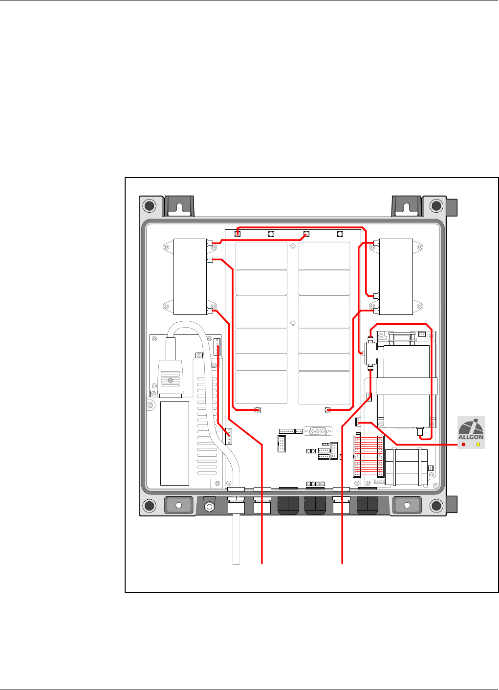
Cabling
On the following pages, you will find cabling information for:
•Compact Repeater With RCC Unit, page 5-16.
•Compact Repeater Without RCC Unit, page 5-17.
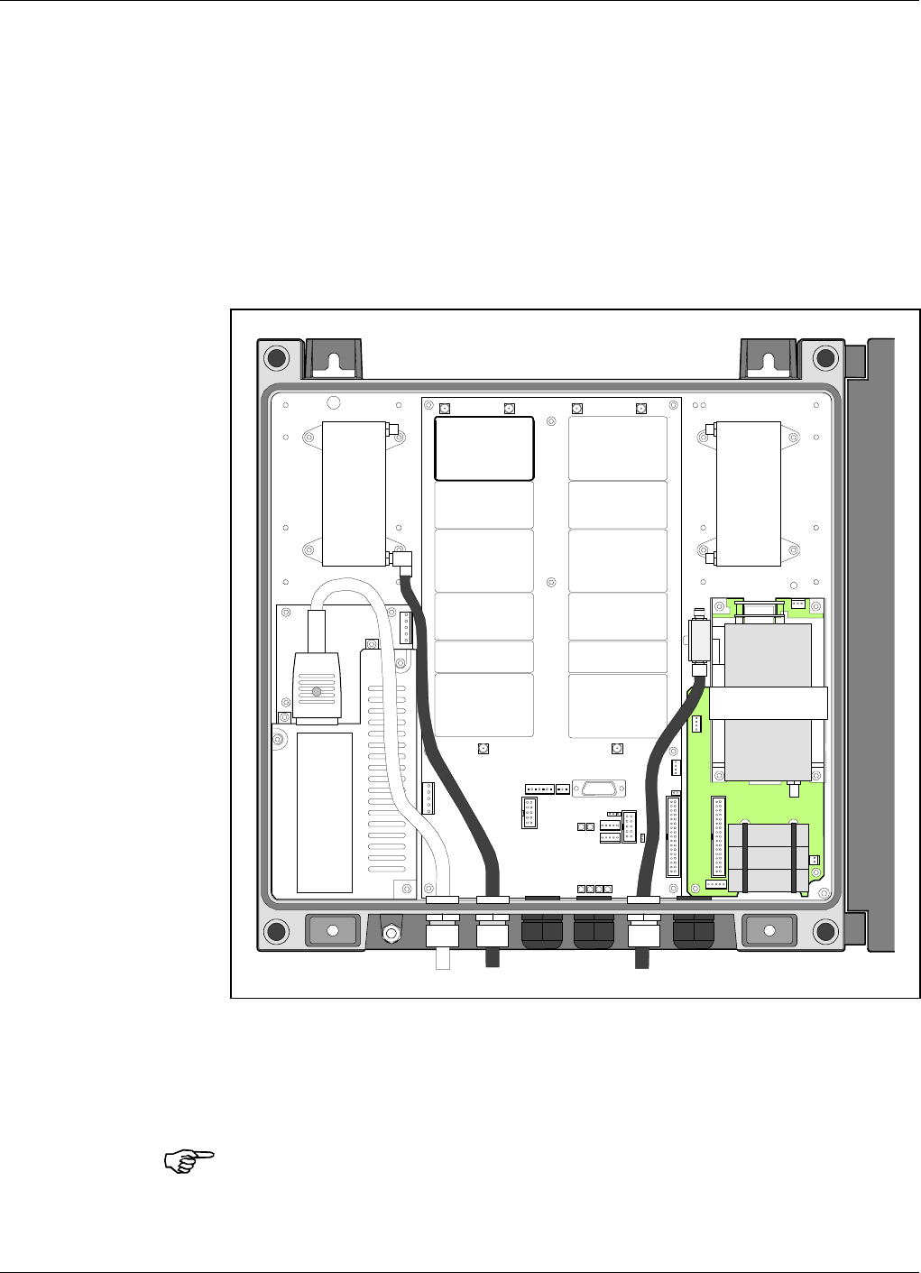
Compact Repeater With RCC Unit
Figure 5-7 shows the compact repeater main cabling with an RCC Remote
Communication Control unit.
ANT
HI
LO
ANT
LO
HI
P126 P127 P122 P123
P121P128
P111
P115
DPC
MS
LNA/ULLNA/DL
PA/ULPA/DL
PSM
CMB/BS
RCC
DPC
BS
MS BS
Figure 5-7. Cabling with RCC unit
Functional Description ALR Compact Repeater ALLGON Systems AB
5 - 16 Rev. P1D 2000-05 VD203 67/EN - User’s Manual
Compact Repeater Without RCC Unit
Figure 5-8 shows the compact repeater main cabling without RCC unit.
ANT
HI
LO
ANT
LO
HI
P126 P127 P122 P123
P121P128
P111
P115
DPC
MS
LNA/ULLNA/DL
PA/ULPA/DL
PSM
CMB/BS
RCC
DPC
BS
MS BS
Figure 5-8. Cabling without RCC unit
ALLGON Systems AB ALR Compact Repeater Functional Description
VD203 67/EN - User’s Manual Rev. P1D 2000-05 5 - 17
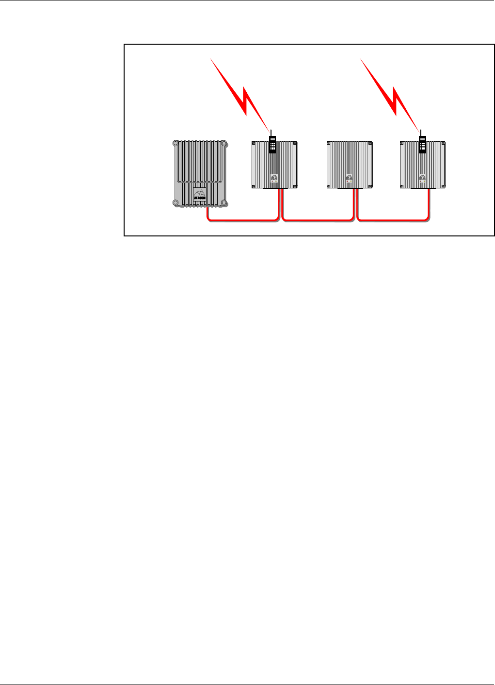
R2R, Repeater To Repeater Link
The Allgon Repeater to Repeater Link can be used in order to establish a
repeater network with up to 13 repeaters, one or several of which can
contain a phone line for communication with an OMT32 or an OMS.
All Allgon standard Compact repeaters include this feature.
All Allgon repeaters can be mixed in R2R nets (see Figure 5-9). For
standard AR repeaters, the R2R Repeater to Repeater Link feature is
optional and require certain hardware and CU software versions.
Installation
All required R2R, Repeater to Repeater Link, circuitry is included in the
compact repeater. Only interconnecting cables are required to set up an
R2R net.
At least one RCC unit (or telephone line with modem) is required for the
remote communication.
Configuration
Configuration is described in AR Repeaters and OMT32, User’s Manual.
Figure 5-9. Repeater to Repeater Link
Functional Description ALR Compact Repeater ALLGON Systems AB
5 - 18 Rev. P1D 2000-05 VD203 67/EN - User’s Manual

6. Optionals
This chapter describes the following optional accessories available for the
Allgon repeaters:
•RCC, Remote Control Unit for band selective systems, page 6-2.
•OMT32, Operation and Maintenance Terminal, page 6-8.
•OMS, Operation and Maintenance System, page 6-8.
•Battery Backup, page 6-8.
•Fiber Optic Interface, page 6-8.
•7/16" Antenna Cable Connectors, page 6-8.
ALLGON Systems AB ALR Compact Repeater Optionals
VD203 67/EN - User’s Manual Rev. P1D 2000-05 6 - 1
RCC, Remote Communication Control Unit
As the mobile phone technology is developing very fast, this RCC may be
modified after issuing this manual. New types may also have been added.
For the latest details, please contact your local Allgon representative.
For remote control of Allgon Compact repeaters in band selective systems
an RCC Remote Communication Control unit is available. This unit
contains an integrated mobile phone, modem and power supply backup.
The RCC unit for the Compact repeater is mounted to the right inside the
repeater cabinet, see Figure 6-1.
The RCC is connected to the P130 port as described in the Connection
section in Chapter 3.
Do not forget to put a jumper between pin 1 and 2 on the P130 connector if
the RCC unit is disconnected.
A jumper should be located in the P113 parking device (a 2-pole connector
used for this purpose).
ANT
ANT
HI LO
LO HI
RCC
Figure 6-1. The RCC unit
Optionals ALR Compact Repeater ALLGON Systems AB
6 - 2 Rev. P1D 2000-05 VD203 67/EN - User’s Manual

OMT32, Operation and Maintenance Terminal
The OMT32, Operation and Maintenance Terminal is an Allgon software
package for configuration and controlling a repeater by using a computer
with Windows 95/98 or NT 4.
The OMT32 can be used either locally, i.e. connected to the repeater, or
remotely via an RCC unit or a traditional telephone line and modem.
All repeater parameters and settings can be configured by menas of the
OMT32.
OMS, Operation and Maintenance System
The OMS, Operation and Maintenance System is an Allgon software
package for controlling a large repeater fleet by using computers with
Windows NT in networks with a common database.
The OMS is capable of operating a large number of repeaters. Multiple
modems can be used for several incoming and outgoing parallel activities,
such as polling, radio parameter configuration, software downloading, etc.
Battery Backup
Battery backup can be arranged by completing the repeater with an 25Ah
or 50Ah Allgon BBU, Battery BackUp unit. The Allgon BBU has an
exterior similar to the repeater which means that it can preferably be
mounted adjacent to the repeater.
Fiber Optic Unit
A FOU, Fiber Optic Unit that includes transmitter, receiver, alarm board
and power supply is available for the Allgon Compact repeater. The fiber
optic interface can be adapted for separate uplink and downlink fiber as
well as for bi-directional one-fiber distribution.
7/16" Antenna Cable Connectors
A 7/16" antenna cable kit is available for the Allgon Compact repeater.
This kit includes 7/16" antenna connectors for uplink and downlink
antennas
ALLGON Systems AB ALR Compact Repeater Optionals
VD203 67/EN - User’s Manual Rev. P1D 2000-05 6 - 3

Index
A
Abbreviations ............................................................................................................ 0-vi
AGC, Automatic Gain Control .................................................................................. 5-7
Alarm .......................................................................................................................... 5-8
AMPS .......................................................................................................................... 2-2
AMPS/DAMPS ........................................................................................................... 5-6
Antenna cable connectors, 7/16" ............................................................................... 6-3
B
Battery backup ........................................................................................................... 6-3
BBU ............................................................................................................................. 6-3
Block diagram ............................................................................................................ 5-6
BOOT, red LED ......................................................................................................... 4-2
BSC, Band Selective Compact board ........... 5-2, 5-3 - 5-4, 5-6, 5-9, 5-10, 5-12 - 5-13
C
Cabling
with RCC ............................................................................................................. 5-16
without RCC ....................................................................................................... 5-17
CDMA ......................................................................................................................... 2-2
CMB, Combiner unit ......................................................................... 5-2 - 5-4, 5-6, 5-9
Commissioning ........................................................................................................... 4-1
Connection .................................................................................................................. 3-6
donor antenna ....................................................................................................... 3-6
external alarm ....................................................................................................... 3-7
internal phone/modem unit ................................................................................. 3-7
mains ..................................................................................................................... 3-6
RCC ........................................................................................................................ 3-7
Repeater to Repeater Link .................................................................................. 3-8
service antenna ..................................................................................................... 3-6
telephone line ........................................................................................................ 3-7
Connection ports ........................................................................................................ 3-9
CU software version ....................................................................................... 5-11, 5-15
CU software and hardware compatibility .............................................................. 5-15
CU, Control Unit ........................................................................... 5-7, 5-10, 5-11, 5-15
D
DAMPS ....................................................................................................................... 2-2
DATA, blue LED ........................................................................................................ 4-3
Dimensions ................................................................................................................. 3-2
DL
See Downlink
Donor antenna .................................................................................. 2-4 - 2-5, 3-5 - 3-6
Door switch ............................................................................................................... 3-12
Downlink ........................................................................................ 5-5 - 5-6, 5-10, 5-13
DPX, Duplex filter ..................................... 5-2 - 5-4, 5-6 - 5-7, 5-9 - 5-10, 5-13 - 5-14
E
EAL1 ......................................................................................................................... 3-11
EAL2 ......................................................................................................................... 3-11
EAL3 ......................................................................................................................... 3-11
EAL4 .............................................................................................................. 3-11 - 3-12
ESD ............................................................................................................................. 1-2
ALLGON Systems AB ALR Compact Repeater Index
VD203 67/EN - User’s Manual Rev. P1D 2000-05 I - 1

External alarm ............................................................................................................ 3-7
External alarm input ............................................................................................... 3-11
F
FAULT, red LED ....................................................................................................... 4-2
Fiber Optic Unit ......................................................................................................... 6-3
Functional description ............................................................................................... 5-1
H
Hail .............................................................................................................................. 3-1
I
Indicators
in the cabinet ......................................................................................................... 4-3
on the repeater front ............................................................................................ 4-2
Introduction ................................................................................................................ 2-1
L
LNA, Low Noise Amplifier ............................................................ 5-6, 5-9 - 5-10, 5-13
M
Mains breakdown relay ............................................................................................ 3-13
Mounting ............................................................................................................ 3-3 - 3-5
Mounting bracket .............................................................................................. 3-3 - 3-5
N
NMT .................................................................................................................... 2-2, 5-6
O
OMS, Operation and Maintenance System ...................................................... 2-1, 6-3
OMT32, Operation and Maintenance Terminal .............................................. 2-1, 6-3
OPER, green LED ...................................................................................................... 4-2
Outdoor installation ................................................................................................... 3-1
P
PA, Power Amplifier ...................................................................... 5-7, 5-9 - 5-10, 5-14
Ports
AI .......................................................................................................................... 3-13
ANT ........................................................................................................................ 5-9
DPX ........................................................................................................................ 5-9
HI .................................................................................................................. 5-9, 5-14
LO ................................................................................................................. 5-9, 5-13
OUT1 ...................................................................................................................... 5-9
P111 ...................................................................................................................... 5-12
P112 PC ...................................................................................... 3-8, 3-10, 5-8, 5-12
P113 Parking device .......................................................................... 3-10, 5-12, 6-2
P115 PSM ............................................................................................................ 5-12
P118 Repeater to Repeater Link ............................................................. 3-10, 5-12
P119 Alarm ...................................................................... 3-7, 3-11 - 3-13, 5-8, 5-12
P120 Door switch ...................................................................................... 3-12, 5-12
P121 ..................................................................................................... 5-9, 5-12, 5-14
P122 ................................................................................................... 5-9, 5-12 - 5-13
P123 ........................................................................................................... 5-12 - 5-13
P124 Repeater to Repeater Link ............................................................. 3-12, 5-12
P126 ................................................................................................... 5-9, 5-12 - 5-13
Index ALR Compact Repeater ALLGON Systems AB
I - 2 Rev. P1D 2000-05 VD203 67/EN - User’s Manual

P127 .......................................................................................................... 5-12 - 5-13
P128 .................................................................................................... 5-9, 5-12, 5-14
P130 RCC ............................................................................ 3-7, 3-12, 5-8, 5-12, 6-2
PSM, Power Supply unit .................................................................................. 5-2 - 5-4
PWR, yellow LED ...................................................................................................... 4-2
R
R2R, green LED ......................................................................................................... 4-3
R2R, Repeater to Repeater Link ....................................... 3-10, 3-12, 4-3, 5-2, 5-2-18
Rain ............................................................................................................................. 3-1
RCC, Remote Communication Control unit ..................................................... 5-2, 6-2
Repeater design .......................................................................................................... 5-2
Repeater setup ........................................................................................................... 5-8
Repeater to Repeater Link
See R2R
Repeater types ............................................................................................................ 2-2
Band selective repeater, adjustable band width ................................................ 2-2
Combined repeater ............................................................................................... 2-2
S
Safety .......................................................................................................................... 1-1
electric shock ......................................................................................................... 1-1
lithium battery ...................................................................................................... 1-1
polytetrafluoro ethylene ....................................................................................... 1-1
PTFE ..................................................................................................................... 1-1
Service antenna ................................................................................. 2-4 - 2-5, 3-5 - 3-6
Service limitations ..................................................................................................... 3-1
Shelter ......................................................................................................................... 3-1
Siting the repeater ..................................................................................................... 3-1
Snow ............................................................................................................................ 3-1
Static electricity ......................................................................................................... 1-2
Station ground ........................................................................................................... 3-9
Sunshine ..................................................................................................................... 3-1
T
TACS/ETACS ...................................................................................................... 2-2, 5-6
Testpoints ................................................................................................................. 5-12
U
UL
See Uplink
Uplink ...................................................................................................... 5-5, 5-10, 5-13
W
Weights ....................................................................................................................... 3-2
ALLGON Systems AB ALR Compact Repeater Index
VD203 67/EN - User’s Manual Rev. P1D 2000-05 I - 3

Questionnaire
The aim of this manual is to guide you when installing and operating the
Allgon repeaters, and to answer questions that may turn up. To ensure
that we provide appropriate information for these purposes, we would
appreciate your views and suggestions on how to improve the manual in
this direction. Please, fill out the following questionnaire and send it to
us.
1
Have you read entire sections or do you use the manual to look up specific
information when needed?
q Read entire sections q Look up specific information
Comments:
2
Do you think the information is easy to find and understand?
q Yes q No
Comments:
3
Do you find any function of the Allgon repeater hard to understand, a
function which should be subjected to more detailed description?
q Yes q No
If yes, which one:
4
Do you have any suggestions on how we can improve this manual?
Title (Mr/Ms/Other): Initial:
Surname: Job title:
Company: Address:
City: Country: Phone:
Thanks for your kind help. It’s very valuable to us.
ALLGON Systems AB ALR Compact Repeater Questionnaire
VD203 67/EN - User’s Manual Rev. P1D 2000-05 Q - 1

Allgon Systems AB
Customer Support Centre
Box 541
S-183 25 Täby
Sweden
If you prefer to send by mail, fold here and tape.
No envelope required.
If you prefer to send by fax, use this number: +46 8 540 824 85
POSTAGE
STAMP
Questionnaire ALR Compact Repeater ALLGON Systems AB
Q - 2 Rev. P1D 2000-05 VD203 67/EN - User’s Manual