Powerwave Technologies AMR23-1200 Microwave Point-to-Point Radio User Manual
Powerwave Technologies Inc. Microwave Point-to-Point Radio
UserManual.wiki
>
Powerwave Technologies
>
AMR23-1200 User Manual
>
users manual
Contents
1.
users manual
2.
rf safety addendum
users manual
Navigation menu
Upload a User Manual
Namespaces
Wiki Guide
HTML
PDF
Info
Views
User Manual
Discussion / Help
Navigation

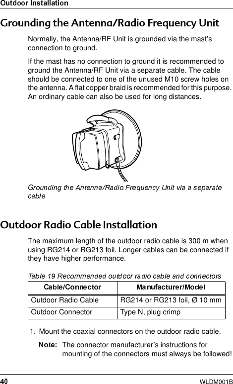
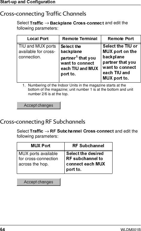
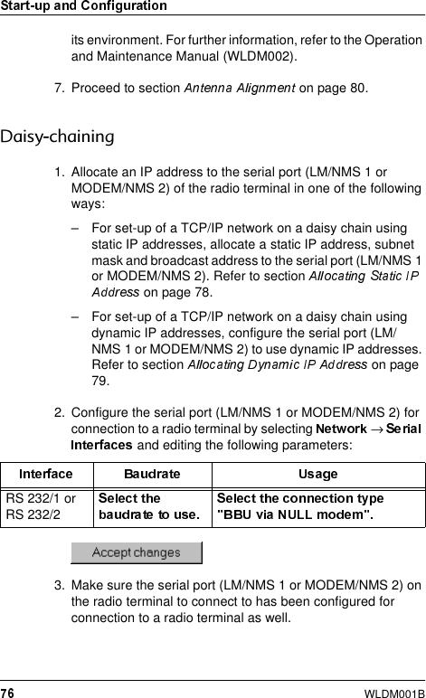
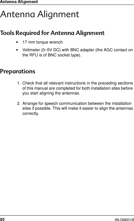
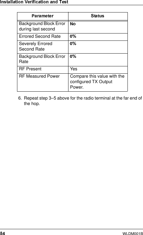
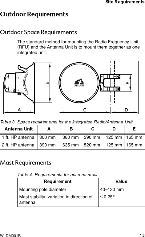
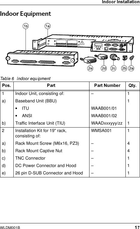
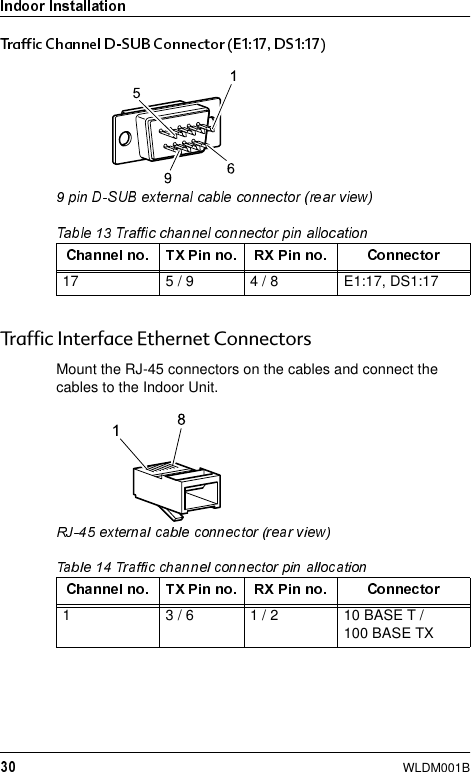
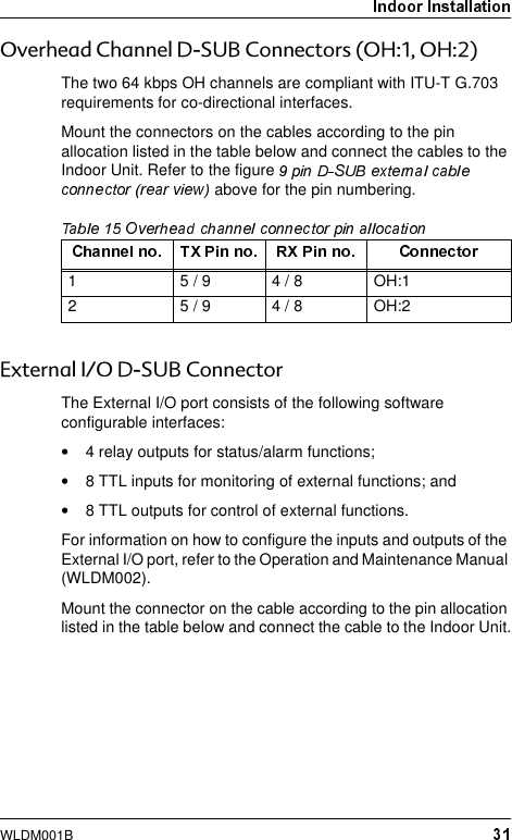
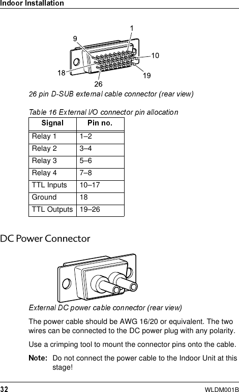
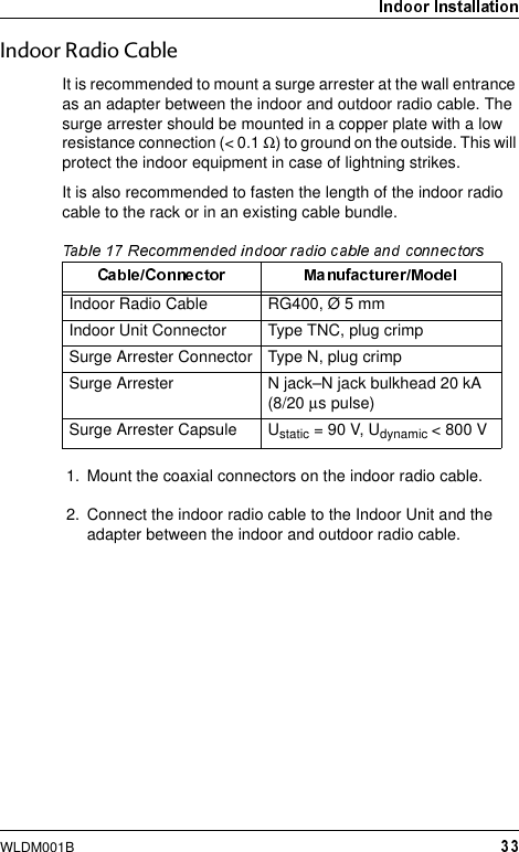
![WLDM001BThe letters x, y and z in the product numbers listed above are variables that depend on the product variant. For further details concerning product numbers, refer to the respective section in this manual and the Product List (WLDM004).All documents, including this manual, also use the ITU standard designations for traffic channels. However, the information is also valid for ANSI standard applications if not otherwise noted.6\QWD[The following typing conventions are used throughout this manual:"Select" Prompts the user to perform a selection on the screen by clicking on an active object."Enter" Prompts the user to type text using the keyboard."Press" Prompts the user to press a button on the keyboard."Check" Prompts the user to click in a check box to activate an option.Prompts the user to enter the command .Prompts the user to enter a value for the variable .[] The user may enter a value for the variable but is not required to.|The user may enter a value for either the variable or the variable .response Text displayed in response to an executed command.Prompts the user to perform a specific action or enter a specific value.](https://usermanual.wiki/Powerwave-Technologies/AMR23-1200.users-manual/User-Guide-135310-Page-6.png)
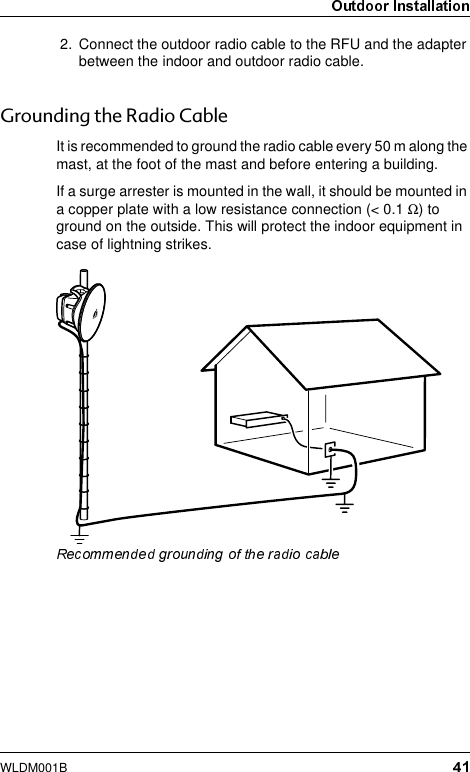
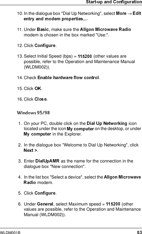
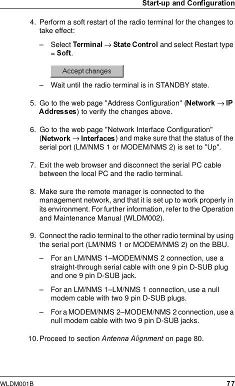
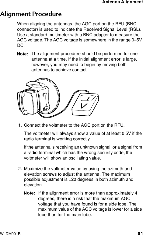
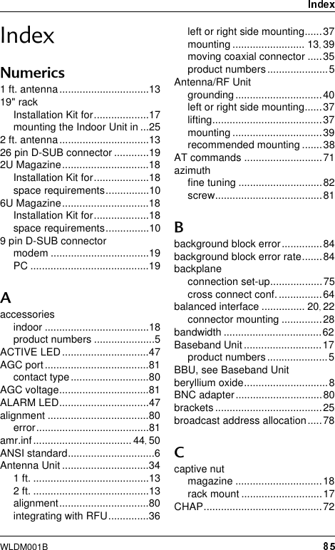
![WLDM001B•Do not use any components (screws, nuts etc.) other than those delivered together with the Allgon Microwave Radio equipment or recommended by Allgon AB.•Use the necessary safety devices (helmet, safety line etc.) when working on, or around the mast. Be aware of the risk of falling objects. Secure the integrated Antenna/Radio Frequency Unit before lifting it up the mast.%HU\OOLXP2[LGHSome components in the Radio Frequency Unit contain beryllium oxide (BeO) which is poisonous if inhaled as dust or smoke. This can only happen if these components are damaged in some way. The product is completely safe as long as the components are not damaged.Warning signs indicate parts containing beryllium oxide.9ROWDJH+D]DUGVBerylliumoxidehazard](https://usermanual.wiki/Powerwave-Technologies/AMR23-1200.users-manual/User-Guide-135310-Page-8.png)

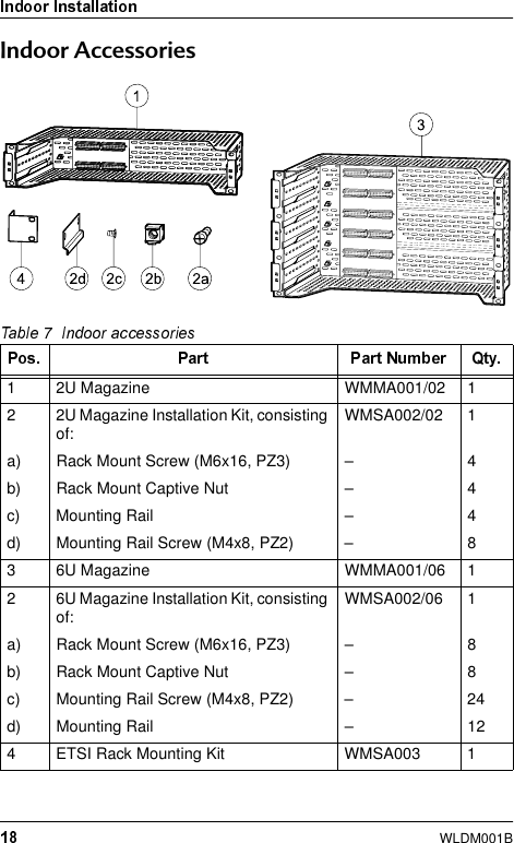
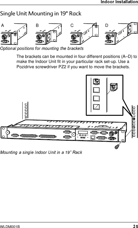
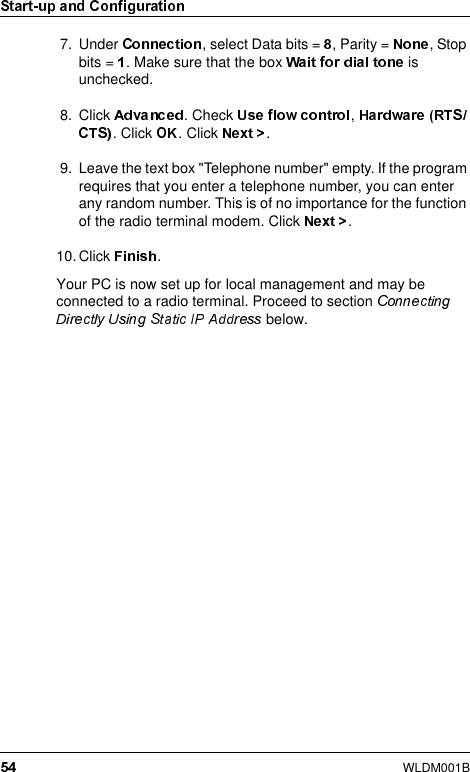
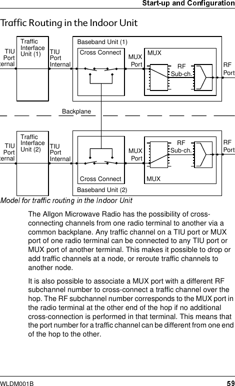
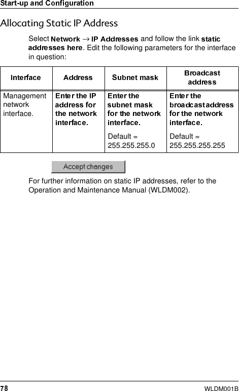
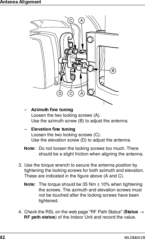
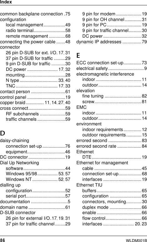
![WLDM001B&RPPRQ%DFNSODQH0RXQWLQJ,Q0DJD]LQHIRU5DFNThe magazine must be mounted in the rack before you remove the transport safety panels.The numbering of the Indoor Units in the magazine starts at the bottom of the magazine; unit number 1 is at the bottom and unit 2 (6) is at the top.](https://usermanual.wiki/Powerwave-Technologies/AMR23-1200.users-manual/User-Guide-135310-Page-26.png)
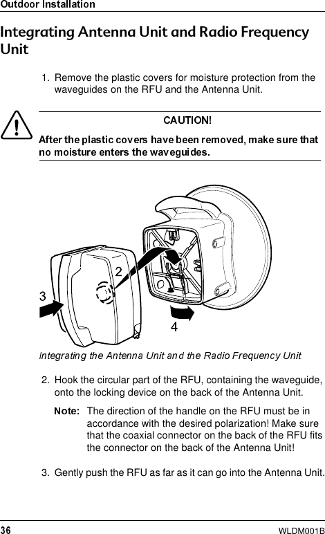
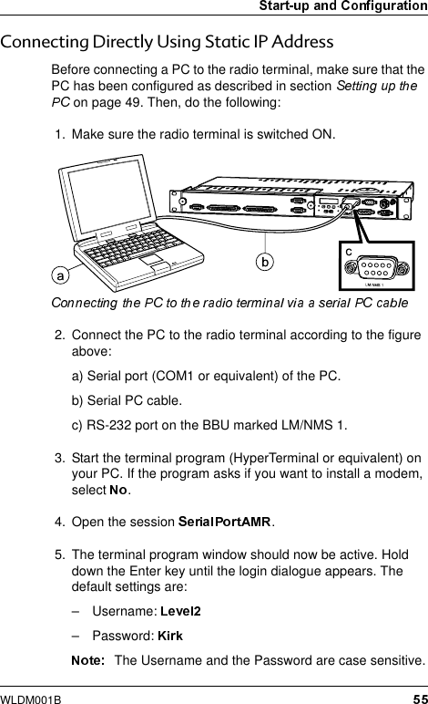
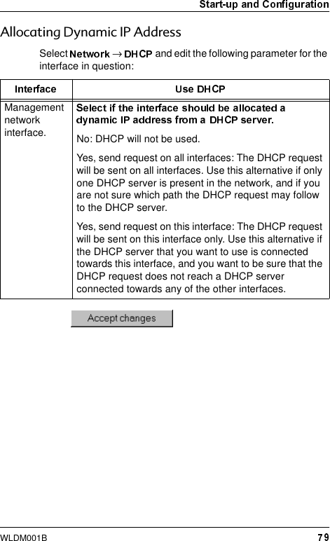
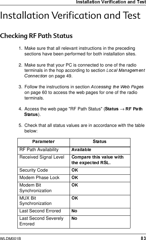
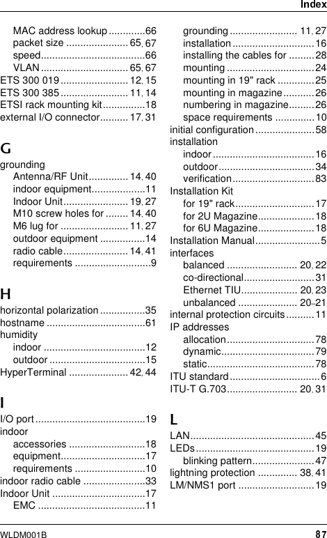
![WLDM001B&KRRVLQJ9HUWLFDORU+RUL]RQWDO3RODUL]DWLRQThe position of the RFU determines the polarization of the radio signal. The handle serves as an indicator: horizontal handle = horizontal polarization, vertical handle = vertical polarization. The coaxial connector on the back of the Antenna Unit must fit the connector on the RFU. Use a Pozidrive screwdriver PZ2 if you need to move the connector on the Antenna Unit.Do not remove the screw or the washer when you move the connector.](https://usermanual.wiki/Powerwave-Technologies/AMR23-1200.users-manual/User-Guide-135310-Page-35.png)