Powerwave Technologies AMR23-1200 Microwave Point-to-Point Radio User Manual
Powerwave Technologies Inc. Microwave Point-to-Point Radio
Contents
- 1. users manual
- 2. rf safety addendum
users manual

$OOJRQ
0LFURZDYH5DGLR
,QVWDOODWLRQ0DQXDO
2WLDM001B

WLDM001B
&RQWHQWV
,QWURGXFWLRQ
Applicable Documents . . . . . . . . . . . . . . . . . . . . . . . . . . . 5
Document Information . . . . . . . . . . . . . . . . . . . . . . . . . . . 5
Syntax . . . . . . . . . . . . . . . . . . . . . . . . . . . . . . . . . . . . . . . 6
6LWH5HTXLUHPHQWV
Safety Requirements . . . . . . . . . . . . . . . . . . . . . . . . . . . . 7
Indoor Requirements . . . . . . . . . . . . . . . . . . . . . . . . . . . 10
Outdoor Requirements . . . . . . . . . . . . . . . . . . . . . . . . . 13
,QGRRU,QVWDOODWLRQ
Tools Required for Indoor Installation . . . . . . . . . . . . . . 16
Indoor Equipment . . . . . . . . . . . . . . . . . . . . . . . . . . . . . 17
Indoor Accessories . . . . . . . . . . . . . . . . . . . . . . . . . . . . 18
Baseband Unit . . . . . . . . . . . . . . . . . . . . . . . . . . . . . . . . 19
Traffic Interface Unit . . . . . . . . . . . . . . . . . . . . . . . . . . . 20
Mounting the Indoor Unit . . . . . . . . . . . . . . . . . . . . . . . . 24
Grounding the Indoor Unit . . . . . . . . . . . . . . . . . . . . . . . 27
Installing the Cables for the Indoor Unit. . . . . . . . . . . . . 28
2XWGRRU,QVWDOODWLRQ
Tools Required for Outdoor Installation. . . . . . . . . . . . . 34
Outdoor Equipment . . . . . . . . . . . . . . . . . . . . . . . . . . . . 34
Choosing Vertical or Horizontal Polarization . . . . . . . . . 35
Integrating Antenna Unit and Radio Frequency Unit . . . 36
Choosing Left or Right Side Antenna Mounting. . . . . . . 37
Fastening the Mast Mounting Bracket . . . . . . . . . . . . . . 38
Mounting the Integrated Antenna/Radio Frequency Unit 39
Grounding the Antenna/Radio Frequency Unit . . . . . . . 40
Outdoor Radio Cable Installation. . . . . . . . . . . . . . . . . . 40
6WDUWXSDQG&RQILJXUDWLRQ
Equipment Required for Configuration . . . . . . . . . . . . . 44
Status LEDs. . . . . . . . . . . . . . . . . . . . . . . . . . . . . . . . . . 47
Start-up and Shut-down. . . . . . . . . . . . . . . . . . . . . . . . . 48
Local Management Connection . . . . . . . . . . . . . . . . . . . 49

WLDM001B
Initial Radio Terminal Configuration. . . . . . . . . . . . . . . . 58
Remote Management Connection . . . . . . . . . . . . . . . . . 68
$QWHQQD$OLJQPHQW
Tools Required for Antenna Alignment . . . . . . . . . . . . . 80
Preparations . . . . . . . . . . . . . . . . . . . . . . . . . . . . . . . . . 80
Alignment Procedure . . . . . . . . . . . . . . . . . . . . . . . . . . . 81
,QVWDOODWLRQ9HULILFDWLRQDQG7HVW
Checking RF Path Status . . . . . . . . . . . . . . . . . . . . . . . 83
,QGH[
WLDM001B
,QWURGXFWLRQ
$SSOLFDEOH'RFXPHQWV
'RFXPHQW,QIRUPDWLRQ
This manual and all documents listed above cover the complete
Allgon Microwave Radio product range:
•Baseband Unit (WAABxxx/yy)
•Traffic Interface Unit (WAADxxxyyy/zz)
•Radio Frequency Unit (WAAAxxxyy/zz)
•Antenna Unit (WAACxxxyy/zz)
•Accessories (WMxxyyy/zz).
This manual describes the installation of the
Allgon Microwave Radio including start-up
and configuration.
This manual describes how to use a web
browser interface to manage the Allgon
Microwave Radio. It also contains
instructions for troubleshooting and
maintenance.
This document contains a detailed technical
description of the Allgon Microwave Radio
product range.
This document lists all equipment and
accessories for the Allgon Microwave Radio.
WLDM001B
The letters x, y and z in the product numbers listed above are
variables that depend on the product variant. For further details
concerning product numbers, refer to the respective section in
this manual and the Product List (WLDM004).
All documents, including this manual, also use the ITU standard
designations for traffic channels. However, the information is also
valid for ANSI standard applications if not otherwise noted.
6\QWD[
The following typing conventions are used throughout this
manual:
"Select" Prompts the user to perform a selection on
the screen by clicking on an active object.
"Enter" Prompts the user to type text using the
keyboard.
"Press" Prompts the user to press a button on the
keyboard.
"Check" Prompts the user to click in a check box to
activate an option.
Prompts the user to enter the command
.
Prompts the user to enter a value for the
variable .
[] The user may enter a value for the variable
but is not required to.
|The user may enter a value for either the
variable or the variable
.
response Text displayed in response to an executed
command.
Prompts the user to perform a specific action
or enter a specific value.
WLDM001B
6LWH5HTXLUHPHQWV
6DIHW\5HTXLUHPHQWV
7HUPLQRORJ\
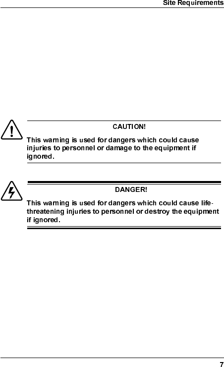
This manual contains two kinds of safety warnings which
represent different degrees of danger:
6DIHW\3UHFDXWLRQV
•Access to the Allgon Microwave Radio shall be restricted to
service personnel.
•Observe the safety warnings and take all precautions listed in
this manual.
•Follow the installation procedures in this manual and use the
correct tools, preferably the recommended tools, for
tightening of nuts etc.
WLDM001B
•Do not use any components (screws, nuts etc.) other than
those delivered together with the Allgon Microwave Radio
equipment or recommended by Allgon AB.
•Use the necessary safety devices (helmet, safety line etc.)
when working on, or around the mast. Be aware of the risk of
falling objects. Secure the integrated Antenna/Radio
Frequency Unit before lifting it up the mast.
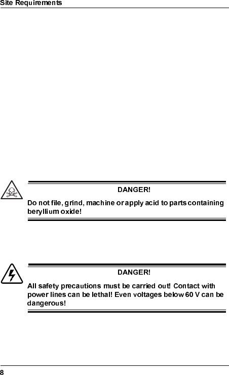
%HU\OOLXP2[LGH
Some components in the Radio Frequency Unit contain beryllium
oxide (BeO) which is poisonous if inhaled as dust or smoke. This
can only happen if these components are damaged in some way.
The product is completely safe as long as the components are
not damaged.
Warning signs indicate parts containing beryllium oxide.
9ROWDJH+D]DUGV
Beryllium
oxide
hazard
WLDM001B
*URXQGLQJ
It is recommended to ground all equipment before the power
cable is connected.
(OHFWULFDO6DIHW\
The Allgon Microwave Radio equipment meets the electrical
safety requirements in EN 60950.
WLDM001B
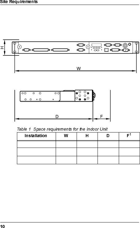
,QGRRU5HTXLUHPHQWV
,QGRRU6SDFH5HTXLUHPHQWV
All interfaces are accessible on the front of the Indoor Unit.
1. Space required for connecting cables and connectors.
Single Indoor Unit 19" 1U 270 mm 70 mm
2U Magazine 19" 2U 2902 mm
2. The units will extend an additional 20 mm in front of the rack,
compared to Single Indoor Unit mounting.
70 mm
6U Magazine 19" 6U 2902 mm 70 mm

WLDM001B
,QGRRU3RZHU5HTXLUHPHQWV
The power supply should be a two wire power distribution
between 20 V and 72 V DC, any polarity.
The radio terminal is equipped with two 5 A fuses on the power
supply input to the Indoor Unit. These fuses are mounted for
safety reasons and can only be exchanged by the manufacturer.
The maximum power consumption is 50 W per radio terminal
(dependent on traffic capacity).
*URXQGLQJRI,QGRRU(TXLSPHQW
Normally, the Indoor Unit is grounded via the rack’s connection to
ground.
If the rack is not connected to ground, it is recommended to
ground the Indoor Unit via a separate cable. The cable should be
connected to the M6 grounding lug located on the front of the
Baseband Unit (BBU). A flat copper braid is recommended for
this purpose.
,QGRRU(OHFWURPDJQHWLF,QWHUIHUHQFH(0&
The Indoor Unit meets the electromagnetic interference
requirements of ETS 300 385.
WLDM001B
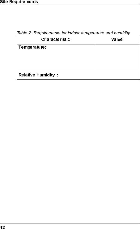
,QGRRU(QYLURQPHQWDO5HTXLUHPHQWV
The Indoor Unit meets the requirements of ETS 300 019-3.
Single units and rack mounted units
with >1U spacing (above and below). -25°C to +55°C
Rack mounted units with <1U spacing. -25°C to +45°C
1
1. See ETS 300 019 for detailed requirements for humidity vs.
temperature.
95% RH
WLDM001B
2XWGRRU5HTXLUHPHQWV
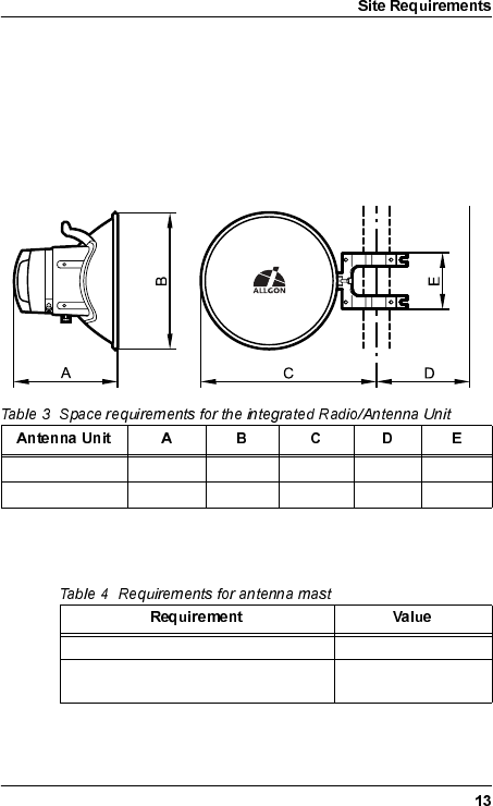
2XWGRRU6SDFH5HTXLUHPHQWV
The standard method for mounting the Radio Frequency Unit
(RFU) and the Antenna Unit is to mount them together as one
integrated unit.
0DVW5HTXLUHPHQWV
1 ft. HP antenna 300 mm 380 mm 390 mm 125 mm 165 mm
2 ft. HP antenna 390 mm 635 mm 520 mm 125 mm 165 mm
Mounting pole diameter 40–130 mm
Mast stability: variation in direction of
antenna ≤ 0.25°
WLDM001B
2XWGRRU3RZHU5HTXLUHPHQWV
Power supply to the outdoor equipment is fed from the BBU via
the radio cable. There is no need for a separate power supply.
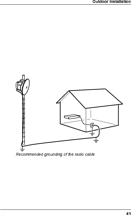
*URXQGLQJRI2XWGRRU(TXLSPHQW
It is recommended to ground the radio cable every 50 metres
along the mast, at the foot of the mast and before entering a
building.
Normally, the Antenna/RF Unit is grounded via the mast’s
connection to ground.
If the mast has no connection to ground it is recommended to
ground the Antenna/RF Unit via a separate cable. The cable
should be connected to one of the unused M10 screw holes on
the antenna. A flat copper braid is recommended for this purpose.
A cable can also be used for long distances.
2XWGRRU(OHFWURPDJQHWLF,QWHUIHUHQFH(0&
The outdoor equipment meets the electromagnetic interference
requirements of ETS 300 385.
WLDM001B
2XWGRRU(QYLURQPHQWDO5HTXLUHPHQWV
The outdoor equipment meets the requirements of
ETS 300 019-4.
1
1. Excluding solar radiation.
-45°C to +45°C
2
2. See ETS 300 019 for detailed requirements for humidity vs.
temperature.
100% RH
WLDM001B
,QGRRU,QVWDOODWLRQ
7RROV5HTXLUHGIRU,QGRRU,QVWDOODWLRQ
•Pozidrive screwdriver PZ2 and PZ3
•Necessary tools for assembling the cables and connectors.
WLDM001B
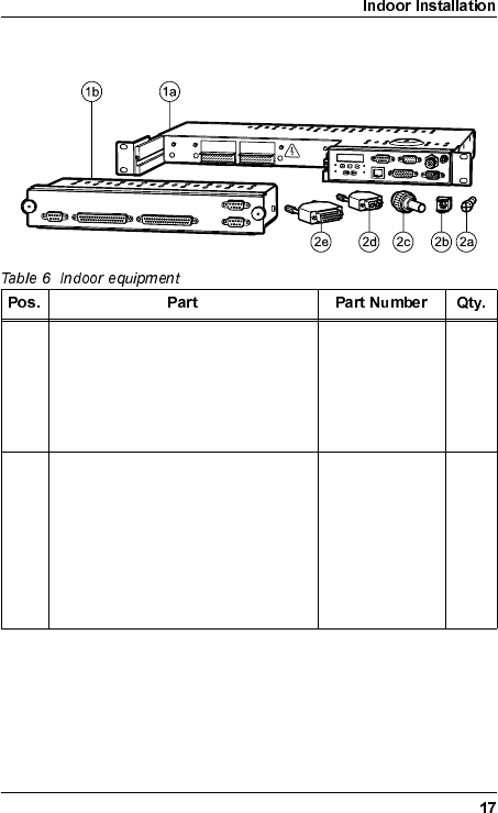
,QGRRU(TXLSPHQW
1 Indoor Unit, consisting of: –1
a) Baseband Unit (BBU) 1
•ITU WAAB001/01
•ANSI WAAB001/02
b) Traffic Interface Unit (TIU) WAADxxxyyy/zz 1
2 Installation Kit for 19" rack,
consisting of: WMSA001 1
a) Rack Mount Screw (M6x16, PZ3) – 4
b) Rack Mount Captive Nut – 4
c) TNC Connector – 1
d) DC Power Connector and Hood – 1
e) 26 pin D-SUB Connector and Hood – 1
WLDM001B
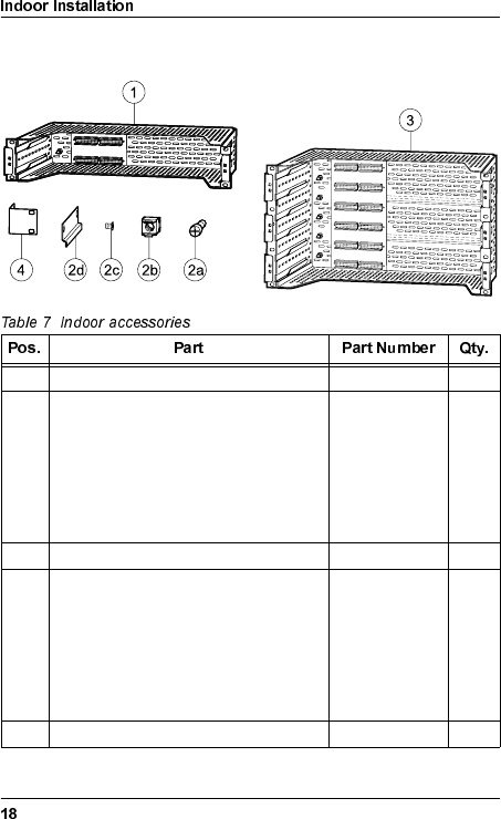
,QGRRU$FFHVVRULHV
1 2U Magazine WMMA001/02 1
2 2U Magazine Installation Kit, consisting
of: WMSA002/02 1
a) Rack Mount Screw (M6x16, PZ3) –4
b) Rack Mount Captive Nut – 4
c) Mounting Rail – 4
d) Mounting Rail Screw (M4x8, PZ2) – 8
3 6U Magazine WMMA001/06 1
2 6U Magazine Installation Kit, consisting
of: WMSA002/06 1
a) Rack Mount Screw (M6x16, PZ3) – 8
b) Rack Mount Captive Nut – 8
c) Mounting Rail Screw (M4x8, PZ2) – 24
d) Mounting Rail – 12
4 ETSI Rack Mounting Kit WMSA003 1
WLDM001B
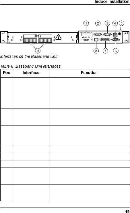
%DVHEDQG8QLW
1 User interface Control panel with keypad and display for
configuring the radio terminal without a PC,
and status LEDs for monitoring of the radio
terminal. For further information about the
control panel, refer to the Operation and
Maintenance Manual (WLDM002).
2 9 pin D-SUB jack LM/NMS 1 port, used for connecting a PC
or for daisy-chaining radio terminals. The
interface standard is RS-232/DCE.
3 9 pin D-SUB plug MODEM/NMS 2, used for modem
connection or for daisy-chaining radio
terminals. The interface standard is RS-
232/DTE.
4 TNC jack Used for connection to the RFU.
5 M6 grounding lug Used for grounding of the Indoor Unit.
6 2 pin D-SUB plug DC power connector.
7 26 pin D-SUB
High Density jack External I/O port, used for monitoring and
control of external functions, and for status/
alarm reporting.
8 RJ-45 jack 10baseT Ethernet port, used for connection
to a LAN. The interface standard is
Ethernet/DTE.
WLDM001B
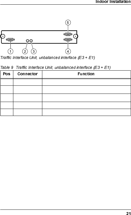
7UDIILF,QWHUIDFH8QLW
All traffic interfaces are located on the TIU of the Indoor Unit. The
interfaces are compliant with ITU-T G.703. Two different types of
interfaces are available:
•Unbalanced interface: SMZ connector, 75 Ω.
•Balanced interface: 9 pin or 37 pin D-SUB connector,
120 Ω(E1) / 100 Ω(DS1).
•Ethernet standard interface: RJ-45 connector.
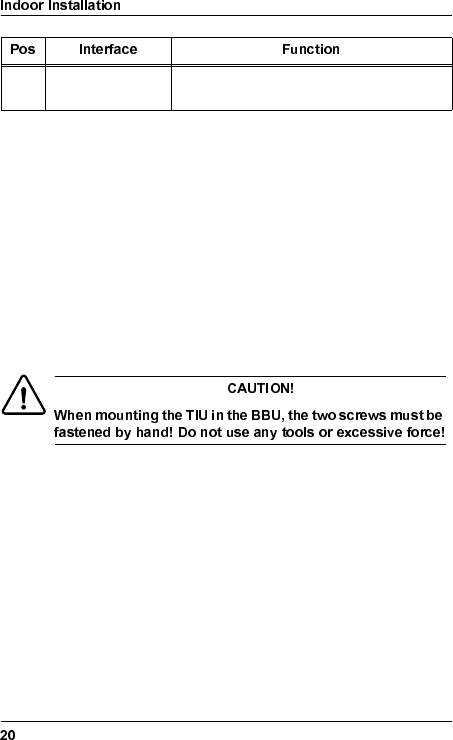
9Sofix1/Metral2
connectors
Used for connection of the TIU.
1. Ericsson designation
2. Berg designation
WLDM001B
8QEDODQFHG,QWHUIDFHV
1 9 pin D-SUB Traffic Channel (E1:17)
2SMZ Traffic Channel (E3:1), outgoing direction (TX)1
1. The channel number and the direction (TX/RX) for the SMZ connectors are
indicated on the TIU.
3SMZ Traffic Channel (E3:1), incoming direction (RX)1
4 9 pin D-SUB Overhead Channel (OH:1)
5 9 pin D-SUB Overhead Channel (OH:2)
WLDM001B
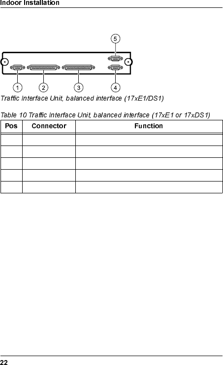
%DODQFHG,QWHUIDFHV
1 9 pin D-SUB Traffic Channel (E1:17 or DS1:17)
2 37 pin D-SUB Traffic Channel (E1:1–8, DS1:1–8)
3 37 pin D-SUB Traffic Channel (E1:9–16, DS1:9–16)
4 9 pin D-SUB Overhead Channel (OH:1)
5 9 pin D-SUB Overhead Channel (OH:2)
WLDM001B
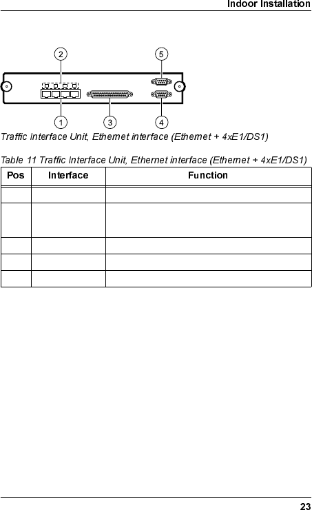
(WKHUQHW,QWHUIDFHV
1 RJ-45 Traffic Channel (10/100baseT)
2 LED, multicolor ON, green: Link available.
ON, orange: Link activity.
3 37 pin D-SUB Traffic Channel (E1:9–12 or DS1:9–12)
4 9 pin D-SUB Overhead Channel (OH:1)
5 9 pin D-SUB Overhead Channel (OH:2)
WLDM001B
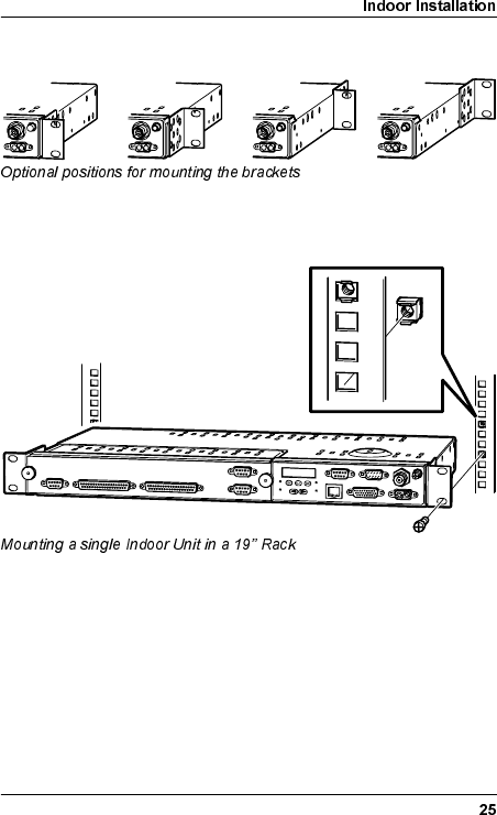
6LQJOH8QLW0RXQWLQJLQ5DFN
The brackets can be mounted in four different positions (A–D) to
make the Indoor Unit fit in your particular rack set-up. Use a
Pozidrive screwdriver PZ2 if you want to move the brackets.
A B C D
WLDM001B
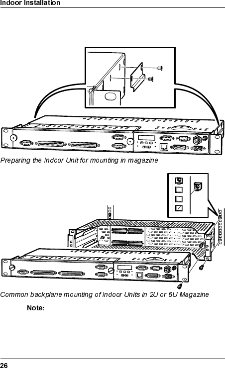
&RPPRQ%DFNSODQH0RXQWLQJ,Q0DJD]LQHIRU
5DFN
The magazine must be mounted in the rack before you
remove the transport safety panels.
The numbering of the Indoor Units in the magazine starts
at the bottom of the magazine; unit number 1 is at the
bottom and unit 2 (6) is at the top.
WLDM001B
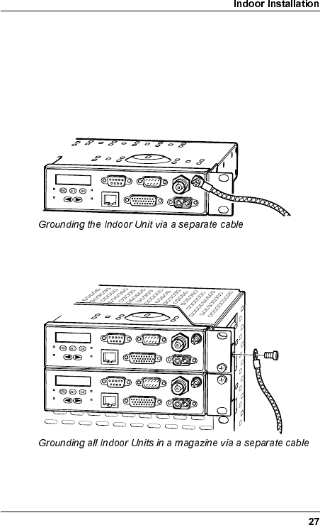
*URXQGLQJWKH,QGRRU8QLW
Normally, the Indoor Unit is grounded via the rack’s connection to
ground.
If the rack is not connected to ground, it is recommended to
ground the Indoor Unit via a separate cable. The cable should be
connected to the M6 grounding lug located on the front of the
BBU. A flat copper braid is recommended for this purpose.
Indoor Units mounted in a magazine can be grounded by
connecting the grounding cable to the M6 grounding lug located
on the magazine.
WLDM001B
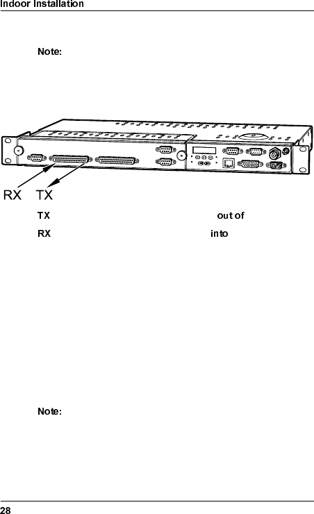
,QVWDOOLQJWKH&DEOHVIRUWKH,QGRRU8QLW
The connector manufacturer’s instructions for mounting
of the connectors must always be followed!
'HILQLWLRQRI7;DQG5;6LJQDOV
signals are defined as signals coming the TIU.
signals are defined as signals going the TIU.
8QEDODQFHG7UDIILF,QWHUIDFH60=&RQQHFWRUV
Mount the SMZ connectors on the cables and connect the cables
to the Indoor Unit. The channel number and the direction (TX/RX)
for each SMZ connector are indicated on the TIU.
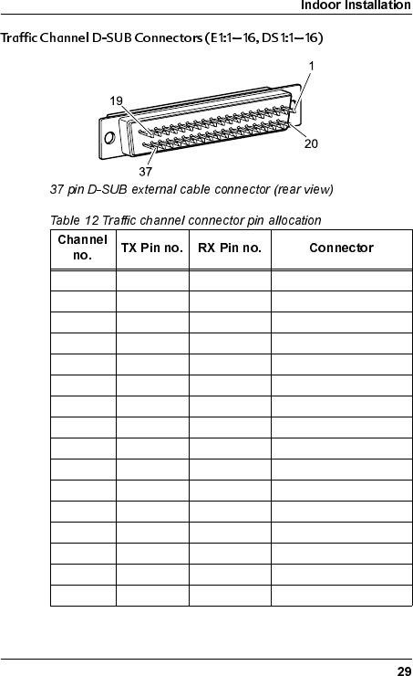
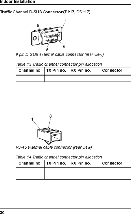
%DODQFHG7UDIILF,QWHUIDFH'68%&RQQHFWRUV
Mount the connectors on the cables according to the pin
allocation listed in the tables below and connect the cables to the
Indoor Unit.
The cables for the balanced traffic interface must be of
type shielded twisted pair!
WLDM001B
1 19 / 37 18 / 36 E1:1–8, DS1:1–8
2 17 /35 16 / 34 E1:1–8, DS1:1–8
3 15 / 33 14 / 32 E1:1–8, DS1:1–8
4 13 / 31 12 / 30 E1:1–8, DS1:1–8
5 11 / 29 10 / 28 E1:1–8, DS1:1–8
6 9 / 27 8 / 26 E1:1–8, DS1:1–8
7 7 / 25 6 / 24 E1:1–8, DS1:1–8
8 5 / 23 4 / 22 E1:1–8, DS1:1–8
9 19 / 37 18 / 36 E1:9–16, DS1:9–16
10 17 / 35 16 / 34 E1:9–16, DS1:9–16
11 15 / 33 14 / 32 E1:9–16, DS1:9–16
12 13 / 31 12 / 30 E1:9–16, DS1:9–16
13 11 / 29 10 / 28 E1:9–16, DS1:9–16
14 9 / 27 8 / 26 E1:9–16, DS1:9–16
15 7 / 25 6 / 24 E1:9–16, DS1:9–16
16 5 / 23 4 / 22 E1:9–16, DS1:9–16
WLDM001B
7UDIILF,QWHUIDFH(WKHUQHW&RQQHFWRUV
Mount the RJ-45 connectors on the cables and connect the
cables to the Indoor Unit.
17 5 / 9 4 / 8 E1:17, DS1:17
1 3 / 6 1 / 2 10 BASE T /
100 BASE TX
WLDM001B
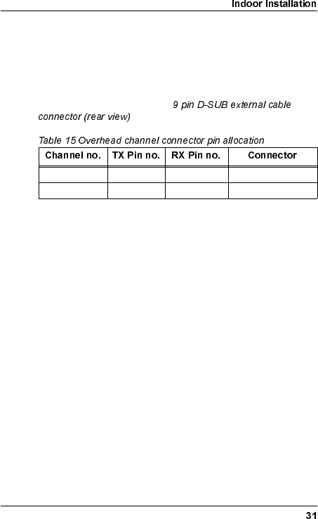
2YHUKHDG&KDQQHO'68%&RQQHFWRUV2+2+
The two 64 kbps OH channels are compliant with ITU-T G.703
requirements for co-directional interfaces.
Mount the connectors on the cables according to the pin
allocation listed in the table below and connect the cables to the
Indoor Unit. Refer to the figure
above for the pin numbering.
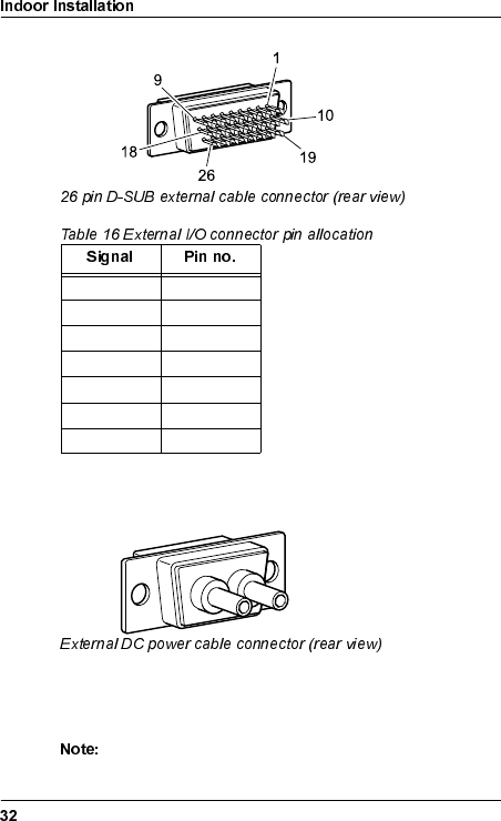
([WHUQDO,2'68%&RQQHFWRU
The External I/O port consists of the following software
configurable interfaces:
•4 relay outputs for status/alarm functions;
•8 TTL inputs for monitoring of external functions; and
•8 TTL outputs for control of external functions.
For information on how to configure the inputs and outputs of the
External I/O port, refer to the Operation and Maintenance Manual
(WLDM002).
Mount the connector on the cable according to the pin allocation
listed in the table below and connect the cable to the Indoor Unit.
1 5 / 9 4 / 8 OH:1
2 5 / 9 4 / 8 OH:2
WLDM001B
'&3RZHU&RQQHFWRU
The power cable should be AWG 16/20 or equivalent. The two
wires can be connected to the DC power plug with any polarity.
Use a crimping tool to mount the connector pins onto the cable.
Do not connect the power cable to the Indoor Unit at this
stage!
Relay 1 1–2
Relay 2 3–4
Relay 3 5–6
Relay 4 7–8
TTL Inputs 10–17
Ground 18
TTL Outputs 19–26
WLDM001B
,QGRRU5DGLR&DEOH
It is recommended to mount a surge arrester at the wall entrance
as an adapter between the indoor and outdoor radio cable. The
surge arrester should be mounted in a copper plate with a low
resistance connection (< 0.1 Ω) to ground on the outside. This will
protect the indoor equipment in case of lightning strikes.
It is also recommended to fasten the length of the indoor radio
cable to the rack or in an existing cable bundle.
1. Mount the coaxial connectors on the indoor radio cable.
2. Connect the indoor radio cable to the Indoor Unit and the
adapter between the indoor and outdoor radio cable.
Indoor Radio Cable RG400, Ø 5 mm
Indoor Unit Connector Type TNC, plug crimp
Surge Arrester Connector Type N, plug crimp
Surge Arrester N jack–N jack bulkhead 20 kA
(8/20 µs pulse)
Surge Arrester Capsule Ustatic = 90 V, Udynamic < 800 V
WLDM001B
2XWGRRU,QVWDOODWLRQ
7RROV5HTXLUHGIRU2XWGRRU,QVWDOODWLRQ
•Pozidrive screwdriver PZ2
•17 mm torque wrench
•Necessary tools for assembling the cables and connectors.
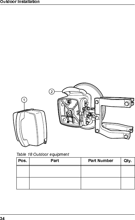
2XWGRRU(TXLSPHQW
1 Radio Frequency Unit
(RFU) WAAAxxxyy/zz 1
2 Antenna Unit (including
Mast Mounting Bracket) WAACxxxyy/zz 1
WLDM001B
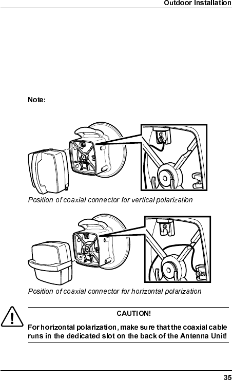
&KRRVLQJ9HUWLFDORU+RUL]RQWDO3RODUL]DWLRQ
The position of the RFU determines the polarization of the radio
signal. The handle serves as an indicator: horizontal handle =
horizontal polarization, vertical handle = vertical polarization.
The coaxial connector on the back of the Antenna Unit must fit
the connector on the RFU. Use a Pozidrive screwdriver PZ2 if
you need to move the connector on the Antenna Unit.
Do not remove the screw or the washer when you move
the connector.
WLDM001B
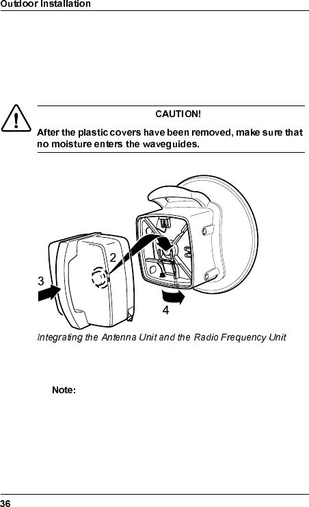
,QWHJUDWLQJ$QWHQQD8QLWDQG5DGLR)UHTXHQF\
8QLW
1. Remove the plastic covers for moisture protection from the
waveguides on the RFU and the Antenna Unit.
2. Hook the circular part of the RFU, containing the waveguide,
onto the locking device on the back of the Antenna Unit.
The direction of the handle on the RFU must be in
accordance with the desired polarization! Make sure
that the coaxial connector on the back of the RFU fits
the connector on the back of the Antenna Unit!
3. Gently push the RFU as far as it can go into the Antenna Unit.
WLDM001B
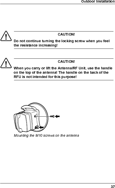
4. Use the 17 mm wrench to fasten the RFU by turning the
locking screw on the bottom of the antenna 1/4 turn. You will
feel a gentle click when the RFU is locked in position. Stop
turning when you feel the resistance increasing.
&KRRVLQJ/HIWRU5LJKW6LGH$QWHQQD0RXQWLQJ
Two M10 screws are used for fastening the Antenna/RF Unit on
the Mast Mounting Bracket. They can be mounted on either side
of the antenna.
•Make sure that the screws are placed in the screw holes on
the correct side of the Antenna Unit, and that there is enough
space to allow mounting of the Antenna/RF Unit to the Mast
Mounting Bracket.
WLDM001B
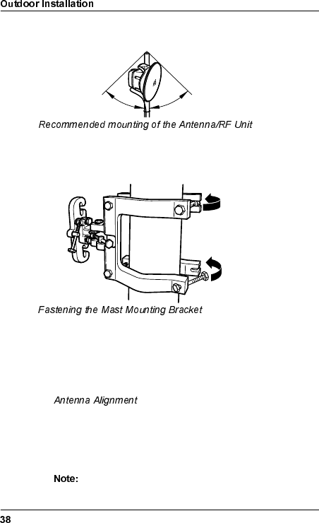
)DVWHQLQJWKH0DVW0RXQWLQJ%UDFNHW
It is recommended to mount the Antenna/RF Unit within a limiting
angle of 45° originating from the top of the mast. This will protect
the Antenna/RF Unit from direct lightning strikes.
1. Position the Mast Mounting Bracket around the mast.
2. Use a compass to roughly align the Mast Mounting Bracket so
that the antenna will point in the radio link path.
Fine tuning will be performed when you reach section
on page 80. The maximum possible fine
tuning adjustment is ±20 degrees in both azimuth and
elevation.
3. Tighten the screws that hold the Mast Mounting Bracket to the
mast with the 17 mm torque wrench.
The torque must be 35 Nm ± 10% when tightening
the screws!
45°45°
WLDM001B
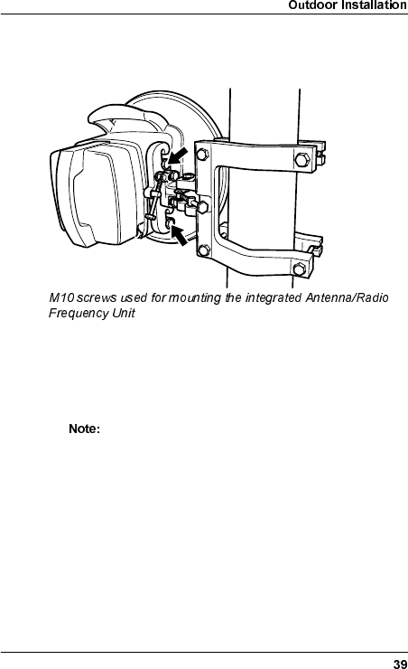
0RXQWLQJWKH,QWHJUDWHG$QWHQQD5DGLR
)UHTXHQF\8QLW
1. Mount the integrated Antenna/RF Unit on the Mast Mounting
Bracket by inserting the two M10 screws in the dedicated
slots.
2. Use the 17 mm torque wrench to tighten the two M10 screws.
The torque must be 35 Nm ± 10% when tightening
the M10 screws!
WLDM001B
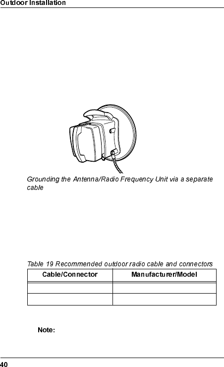
*URXQGLQJWKH$QWHQQD5DGLR)UHTXHQF\8QLW
Normally, the Antenna/RF Unit is grounded via the mast’s
connection to ground.
If the mast has no connection to ground it is recommended to
ground the Antenna/RF Unit via a separate cable. The cable
should be connected to one of the unused M10 screw holes on
the antenna. A flat copper braid is recommended for this purpose.
An ordinary cable can also be used for long distances.
2XWGRRU5DGLR&DEOH,QVWDOODWLRQ
The maximum length of the outdoor radio cable is 300 m when
using RG214 or RG213 foil. Longer cables can be connected if
they have higher performance.
1. Mount the coaxial connectors on the outdoor radio cable.
The connector manufacturer’s instructions for
mounting of the connectors must always be followed!
Outdoor Radio Cable RG214 or RG213 foil, Ø 10 mm
Outdoor Connector Type N, plug crimp
WLDM001B
2. Connect the outdoor radio cable to the RFU and the adapter
between the indoor and outdoor radio cable.
*URXQGLQJWKH5DGLR&DEOH
It is recommended to ground the radio cable every 50 m along the
mast, at the foot of the mast and before entering a building.
If a surge arrester is mounted in the wall, it should be mounted in
a copper plate with a low resistance connection (< 0.1 Ω) to
ground on the outside. This will protect the indoor equipment in
case of lightning strikes.
WLDM001B
6WDUWXSDQG&RQILJXUDWLRQ
The radio terminal can be managed either locally or remotely.
When accessing the radio terminal for the first time, you must
manage it locally. During the initial configuration, you should
configure it for remote management to be able to manage it
remotely subsequently.
You only have to carry out the instructions in this section
the first time you access the radio terminal. If you have
accessed the radio terminal before and configured the
ports that you will use for communicating with it, proceed
to section on page 60.
The easiest way to configure the radio terminal is by using a web
browser. In order to establish communication between the web
browser and the radio terminal you must first configure the
communication interface.
In some cases you may need to use a text terminal program for
this purpose. The instructions in this manual are written for the
HyperTerminal program which is included in Windows 95/98/NT.
However, other communication applications can also be used.
The management connection depends on whether the radio
terminal should have static or dynamic IP addresses. For more
information about this, refer to the Operation and Maintenance
Manual (WLDM002).
When accessing the radio terminal for the first time, do the
following:
1. Switch on the radio terminal. Refer to section
on page 48.
2. Connect the radio terminal to a local manager. Refer to
section on page 49.
3. Perform initial radio terminal configuration. Refer to section
on page 58.
WLDM001B
4. Connect the radio terminal to a remote manager according to
one of the following alternatives:
– For set-up of a TCP/IP network on an Ethernet LAN, refer
to section on page 68.
– For set-up of a TCP/IP network via a modem, refer to
section on page 70.
– For set-up of a TCP/IP network via an ECC, refer to
section on page 73.
Alternatively, you may connect the radio terminal to another
radio terminal already connected to a remote manager. Do
this according to one of the following alternatives:
– For set-up of a TCP/IP network via a common backplane,
refer to section on
page 75.
– For set-up of a TCP/IP network on a daisy chain, refer to
section on page 76.
– For set-up of a TCP/IP network on an Ethernet LAN, refer
to section on page 68.
WLDM001B
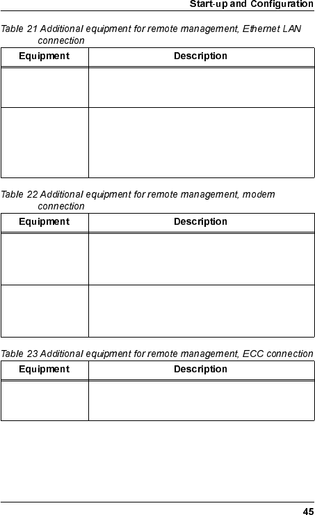
(TXLSPHQW5HTXLUHGIRU&RQILJXUDWLRQ
lists the equipment required for configuration of the
radio terminal on site, i.e. to establish a local management
connection.
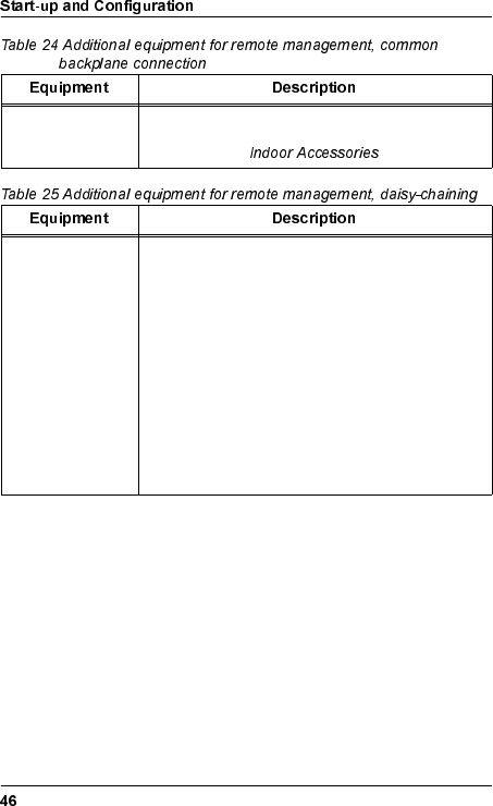
– list additional equipment required to establish
a remote management connection. The required equipment
depends on which type of remote management network you are
going to install the radio terminal in.
PC This manual describes how to use a PC with
Windows installed as local manager. Other
platforms can be used, but this is not described.
Windows 95/98 or
NT 4.0 Operating
System
Operating system for PC. Other operating systems
are possible.
Web Browser Used as operator interface. The web browser
could be Netscape Navigator 4.0 or Internet
Explorer 4.0, or later versions.
Text Terminal Used as operator interface to send commands
directly to the Management Information Base via
RS-232 serial interface. The text terminal could be
HyperTerminal, which is usually included in
Windows, or equivalent.
Dial Up
Networking
Software
Used for dialling up via the serial port. This
software is included in Windows but not always
installed by default.
The file "amr.inf" Supplied by Allgon AB on the disc marked "AMR
Software".
Serial PC Cable For connection of the PC to the radio terminal. The
interface in the radio terminal end should be a
9 pin D-SUB plug. The interface in the other end
should fit the serial port of your PC (e.g. COM1).
WLDM001B
TCP/IP-based
LAN For connection of a remote manager. For further
information, refer to the Operation and
Maintenance manual (WLDM002).
UTP Cable For connection of the radio terminal to an Ethernet
LAN.
If two radio terminals are to be connected to each
other, connect them directly using a null modem
UTP cable (DTE-wired in both ends).
Modems For placement at the radio terminal site and a
remote manager site respectively. For further
information, refer to the Operation and
Maintenance manual (WLDM002).
Serial Modem
Cable For connection of a modem to the radio terminal.
The interface in the radio terminal end should be a
9 pin D-SUB jack. The interface in the other end
should fit the serial port of your modem.
Ethernet E1/DS1
Router For routing of ECCs to a remote manager. For
further information, refer to the Operation and
Maintenance manual (WLDM002).
WLDM001B
2U Magazine or
6U Magazine For connection of two or six radio terminals
mounted in the same rack. For further information,
refer to section on page 18.
Serial Cable For connection of two radio terminals via the serial
interfaces.
•For an LM/NMS 1–MODEM/NMS 2
connection, use a straight-through serial cable
with one 9 pin D-SUB plug and one 9 pin D-
SUB jack.
•For an LM/NMS 1–LM/NMS 1 connection, use
a null modem cable with two 9 pin D-SUB
plugs.
•For a MODEM/NMS 2–MODEM/NMS 2
connection, use a null modem cable with two
9 pin D-SUB jacks.
WLDM001B
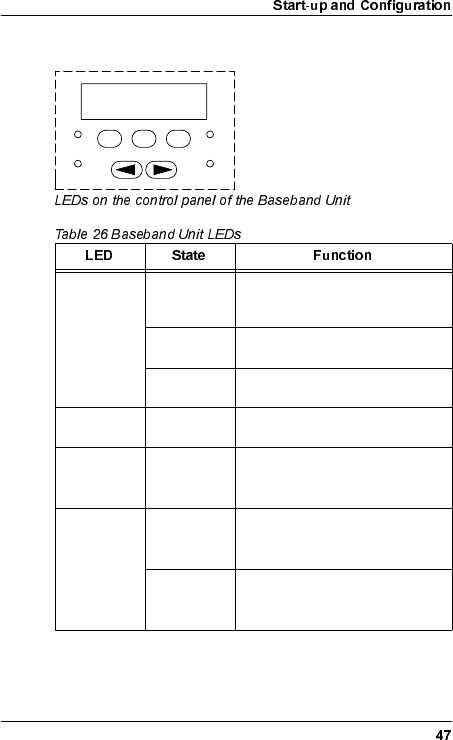
6WDWXV/('V
ACTIVE1
1. The radio terminal can be in either NORMAL mode or in TEST
mode. The blinking pattern for the ACTIVE LED is the same in
both modes.
OFF The radio terminal is starting up
or reconfiguring (INACTIVE
state).
Blinks 1 Hz The radio terminal is ready to
transmit (STANDBY state).
Blinks 15 Hz The radio terminal is transmitting
(ACTIVE state).
TEST Blinks 15 Hz The radio terminal is in TEST
mode.
WARNING ON An alarm of severity WARNING2
has been generated in the radio
terminal.
2. These alarms are software-configurable. For further information,
refer to the Operation and Maintenance manual (WLDM002).
ALARM ON An alarm of severity ALARM2
has been generated in the radio
terminal.
Blinks 3 Hz An alarm of severity SEVERE
ALARM2 has been generated in
the radio terminal.
ESC ALT OK
TEST
ACTIVE
ALARM
WARNING
WLDM001B
6WDUWXSDQG6KXWGRZQ
6ZLWFKLQJ21WKH5DGLR7HUPLQDO
1. Make sure that the power supply feeding the BBU has an
output voltage somewhere between 20 V and 72 V, any
polarity.
2. Connect the power cable to the BBU.
3. During start-up, the TEST LED blinks with 15 Hz. Wait until
the system is in STANDBY state (this normally takes around
30 seconds); the ACTIVE LED should blink (1 Hz or 15 Hz)
and all other LEDs should be switched off before you start to
configure the radio terminal.
6ZLWFKLQJ2))WKH5DGLR7HUPLQDO
Before you have started to configure the radio terminal via the
web interface, you can switch off the radio terminal at any time by
disconnecting the power cable.
After you have reached section on
page 60, and have started to configure the radio terminal via the
web interface, you should do the following to prevent the radio
terminal from transmitting transients at switch off:
1. Select → ; set "TX Mute" to .
2. Disconnect the power cable.
WLDM001B
/RFDO0DQDJHPHQW&RQQHFWLRQ
Before connecting the radio terminal to local management
equipment, in this case a PC, you must prepare the PC according
to section below. When this is done, connect
the radio terminal locally by setting up a point-to-point network
between the radio terminal and the PC using a static IP address.
Refer to section on
page 55.
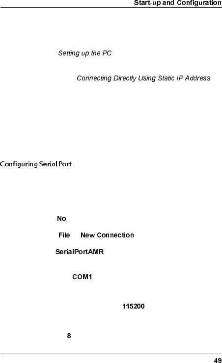
6HWWLQJXSWKH3&
This section describes how to set up your PC to be able to
connect it locally to any radio terminal. You only have to carry out
the instructions in this section once.
You must create a text terminal session with the correct settings
for the serial port that will be used for radio terminal connection.
1. Start the terminal program (HyperTerminal or equivalent) on
your PC. If the program asks if you want to install a modem,
select .
2. Select → .
3. Enter as the name and select an icon for the
connection.
4. Connect to or equivalent serial port.
5. The port settings for the serial port should be:
– Bits Per Second (bps) = (other values are
possible, refer to the Operation and Maintenance Manual
(WLDM002))
– Bits =
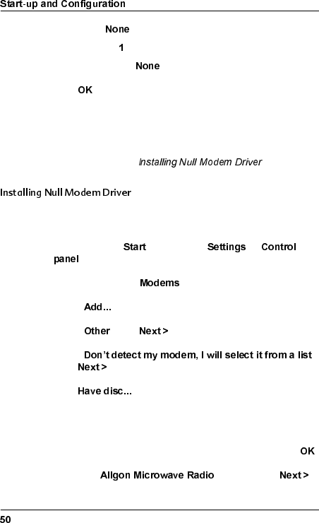
WLDM001B
– Parity =
–Stop Bits =
– Flow Control =
6. Click .
7. Save the session.
8. Exit the HyperTerminal program and close the connection.
9. Proceed to section below.
The radio terminal is seen as a telephone modem by the PC. You
must therefore install a null modem driver on your PC.
1. In the Windows menu, select →
.
2. Double click on the icon.
3. Select .
4. Select . Click .
5. Select .
Click .
6. Click
7. Insert the computer disc marked "AMR Software" containing
the file "amr.inf" in your PC.
8. Select the path to where the file “amr.inf” is stored. Click .
9. Select the modem. Click .
WLDM001B
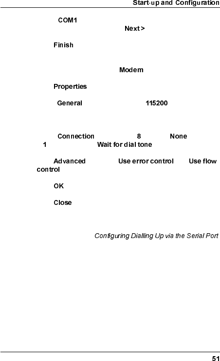
10. Select or equivalent serial port that you want to
connect the modem to. Click .
11. Click .
12. If the dialogue box “Modem properties” does not automatically
appear, double click on the icon in the Control panel.
13. Click .
14. Under , select Max speed = (other values are
possible, refer to the Operation and Maintenance Manual
(WLDM002)).
15. Under , select Bits = , Parity = , Stop bits
= . Make sure that is unchecked.
16. Click . Uncheck and
.
17. Click two times.
18. Click .
19. Restart your computer for the changes to take effect.
20. Proceed to section
below.
WLDM001B
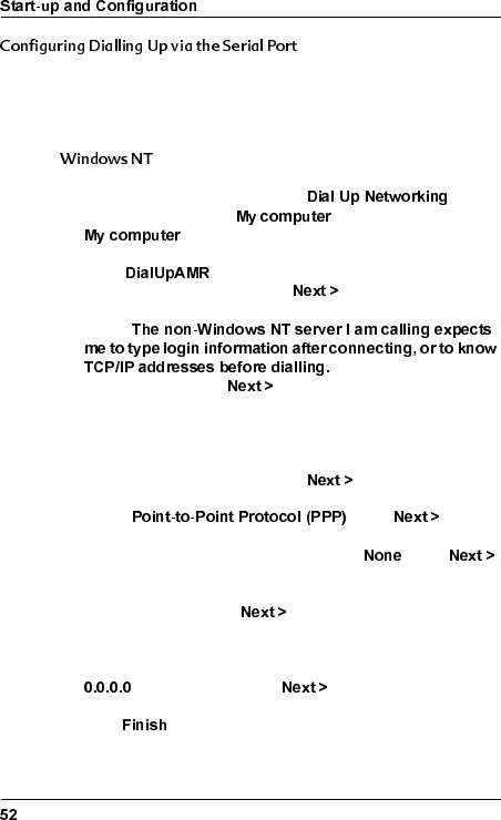
The configuration for dialling up the radio terminal via the serial
port depends on which operating system you are using on your
PC; choose the correct alternative below.
1. On your PC, double click on the icon
located under the icon on the desktop, or under
in the Explorer.
2. Enter as the Entry name in the dialogue box
"New phonebook entry". Click .
3. Check
; all other boxes should
be unchecked. Click .
4. Leave the text box "Telephone number" empty. If the program
requires that you enter a telephone number, enter any
random number. This is of no importance for the function of
the radio terminal modem. Click .
5. Select . Click .
6. In the "Login script" dialogue box, select . Click .
7. Enter the IP address of your computer in the text box marked
"My IP address". Click .
8. If there is a DNS server in your network, enter its IP address
in the dedicated text box. If you have no DNS server, enter
in this text box. Click .
9. Click .
WLDM001B
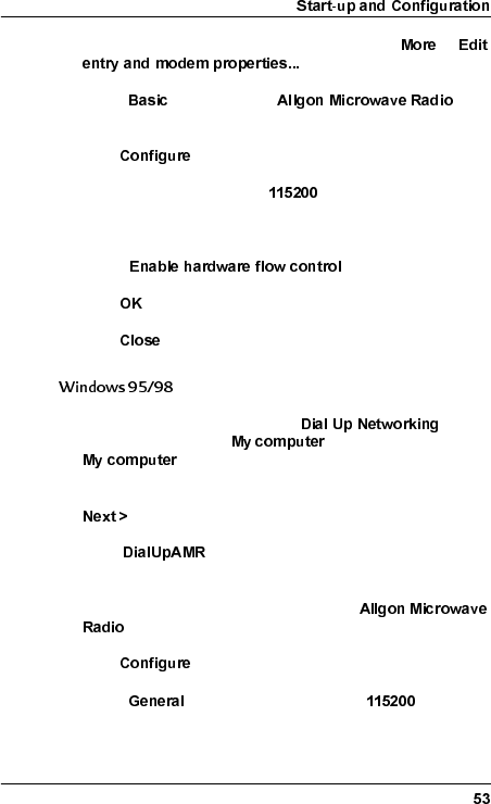
10. In the dialogue box "Dial Up Networking", select →
.
11. Under , make sure the
modem is chosen in the box marked "Use:".
12. Click .
13. Select Initial Speed (bps) = (other values are
possible, refer to the Operation and Maintenance Manual
(WLDM002)).
14. Check .
15. Click .
16. Click .
1. On your PC, double click on the icon
located under the icon on the desktop, or under
in the Explorer.
2. In the dialogue box "Welcome to Dial Up Networking", click
.
3. Enter as the name for the connection in the
dialogue box "New connection".
4. In the list box "Select a device", select the
modem.
5. Click .
6. Under , select Maximum speed = (other
values are possible, refer to the Operation and Maintenance
Manual (WLDM002)).
WLDM001B
7. Under , select Data bits = , Parity = , Stop
bits = . Make sure that the box is
unchecked.
8. Click . Check ,
. Click . Click .
9. Leave the text box "Telephone number" empty. If the program
requires that you enter a telephone number, you can enter
any random number. This is of no importance for the function
of the radio terminal modem. Click .
10. Click .
Your PC is now set up for local management and may be
connected to a radio terminal. Proceed to section
below.
WLDM001B
&RQQHFWLQJ'LUHFWO\8VLQJ6WDWLF,3$GGUHVV
Before connecting a PC to the radio terminal, make sure that the
PC has been configured as described in section
on page 49. Then, do the following:
1. Make sure the radio terminal is switched ON.
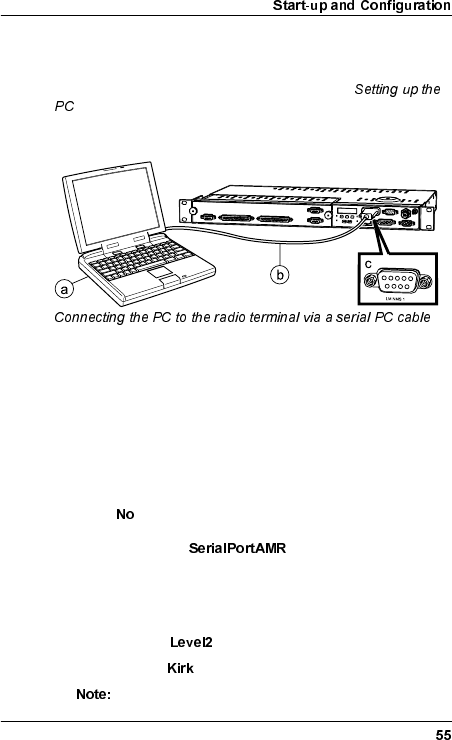
2. Connect the PC to the radio terminal according to the figure
above:
a) Serial port (COM1 or equivalent) of the PC.
b) Serial PC cable.
c) RS-232 port on the BBU marked LM/NMS 1.
3. Start the terminal program (HyperTerminal or equivalent) on
your PC. If the program asks if you want to install a modem,
select .
4. Open the session .
5. The terminal program window should now be active. Hold
down the Enter key until the login dialogue appears. The
default settings are:
– Username:
– Password:
The Username and the Password are case sensitive.
WLDM001B
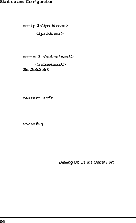
6. Allocate an IP address to the serial port LM/NMS 1 of the
radio terminal by executing the command
where is the desired IP address.
7. Allocate a subnet mask to the serial port by executing the
command
where is the desired subnet mask (default =
).
8. After you have changed the system settings according to step
9–10 above, you must restart the terminal for the changes to
take effect. Execute the command
and wait until the terminal is ready and idle again.
9. Log in and use the command
to verify that the commands in step 9–10 above were
successfully executed. This command will return the current
IP addresses for the ports of the radio terminal.
10. Exit the HyperTerminal program and close the connection.
11. Proceed to section below.
WLDM001B
'LDOOLQJ8SYLDWKH6HULDO3RUW
The procedure for dialling up the radio terminal via the serial port
depends on which operating system you are using on your PC;
choose the correct alternative below.
1. On your PC, double click on the Dial Up Networking icon
located under the icon for "My computer" on the desktop, or
under "My computer" in the Explorer.
2. Select .
3. A login dialogue box should now appear. The default settings
are:
– Username:
– Password:
The Username and the Password are case sensitive.
4. Proceed to section below.
1. On your PC, double click on the Dial Up Networking icon
located under the icon "My computer" on the desktop, or
under "My computer" in the Explorer.
2. Double click on the icon under Dial Up
Networking located under the icon "My computer" on the
desktop, or under "My computer" in the Explorer.
3. A login dialogue box should now appear. The default settings
are:
– Username:
– Password:
WLDM001B
The Username and the Password are case sensitive.
4. Click .
5. Proceed to section below.
,QLWLDO5DGLR7HUPLQDO&RQILJXUDWLRQ
To get the radio terminal up and running, the minimum
configuration you must perform is as follows:
1. Access the web pages of the radio terminal. Refer to section
on page 60.
2. Supply the radio terminal with system information. Refer to
section on page 61.
3. Configure the RF channel. Refer to section
on page 62.
4. Configure the traffic channels. Refer to section
on page 63.
5. Configure the backplane cross-connections. Refer to section
on page 64.
6. Configure the RF subchannel cross-connections. Refer to
section on page 64.
7. If applicable, configure the Ethernet traffic interface. Refer to
section on page 65.
8. Proceed to section on
page 68.
WLDM001B
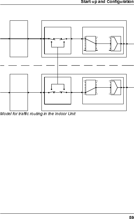
7UDIILF5RXWLQJLQWKH,QGRRU8QLW
The Allgon Microwave Radio has the possibility of cross-
connecting channels from one radio terminal to another via a
common backplane. Any traffic channel on a TIU port or MUX
port of one radio terminal can be connected to any TIU port or
MUX port of another terminal. This makes it possible to drop or
add traffic channels at a node, or reroute traffic channels to
another node.
It is also possible to associate a MUX port with a different RF
subchannel number to cross-connect a traffic channel over the
hop. The RF subchannel number corresponds to the MUX port in
the radio terminal at the other end of the hop if no additional
cross-connection is performed in that terminal. This means that
the port number for a traffic channel can be different from one end
of the hop to the other.
Baseband Unit (1)
MUX
Port RF
Sub-ch.
RF
Port
MUX
Backplane
Cross Connect
TIU
Port
Internal
Traffic
Interface
Unit (1)
TIU
Port
t
ernal
MUX
Port
RF
Sub-ch.
RF
Port
MUX
Cross Connect
Traffic
Interface
Unit (2)
TIU
Port
t
ernal
Baseband Unit (2)
TIU
Port
Internal
WLDM001B
Before starting traffic configuration, a system administrator must
have planned the radio terminal network concerning frequency
bands, traffic load, and so on.
For further information on the traffic routing in the radio
terminal, refer to the Operation and Maintenance Manual
(WLDM002).
$FFHVVLQJWKH:HE3DJHV
1. Start the web browser on your PC/management equipment.
2. Enter the name or the IP address of the radio terminal in the
URL address box marked "Location" (Netscape) or "Address"
(Explorer).
3. A login dialogue box should now appear. The default settings
are:
– Username:
– Password:
The Username and the Password are case sensitive.
4. You will now automatically be transferred to the main page of
the radio terminal. Choose the web page that you want to
access in the pull-down menus at the top of the web pages.
The first time you access the web pages, you should
change the default password settings. Do this on the web
page "Access Level Configuration" ( →
).
WLDM001B
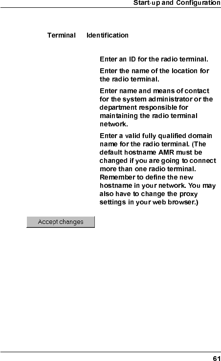
(GLWLQJ6\VWHP,QIRUPDWLRQ
Select →, and edit the following
parameters:
Terminal ID:
Terminal location:
Contact:
Domain name:
WLDM001B
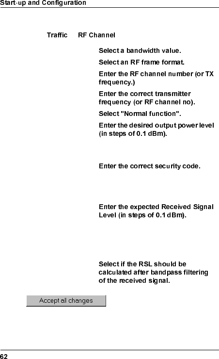
&RQILJXULQJWKH5)&KDQQHO
Select → and edit the following parameters:
Bandwidth
RF frame format
RF channel no
TX frequency
TX mute
Output power
≤19 dBm for 37–40 GHz, ≤20 dBm for
21–30 GHz.
Security code
0–255; this number must be the same
for the terminals at both ends of the
hop.
Expected RSL
The RSL value will correspond to a
maximum ideal AGC voltage level of
3.5 V on the RFU when you align the
antenna.
Use channel filter in
RSL calculation
WLDM001B
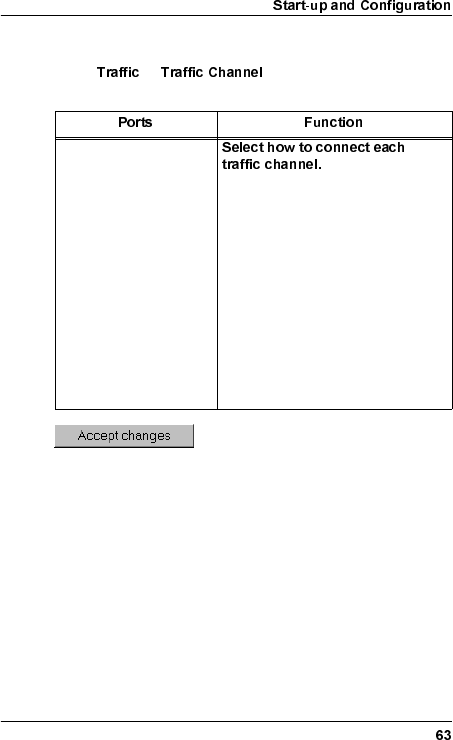
&RQQHFWLQJWKH7UDIILF&KDQQHOV
Select → and edit the following
parameters:
Traffic channels from
the TIU. These
correspond to the traffic
ports on the front of the
terminal.
•Not used: The traffic channel will
not be used for any traffic.
•Connect to MUX: The traffic
channel will be connected to the
MUX and transmitted by this
radio terminal.
•Cross-connect: The traffic
channel will be connected to the
backplane for cross-connection
to another radio terminal
(provided that the radio terminal
is connected to a backplane).
WLDM001B
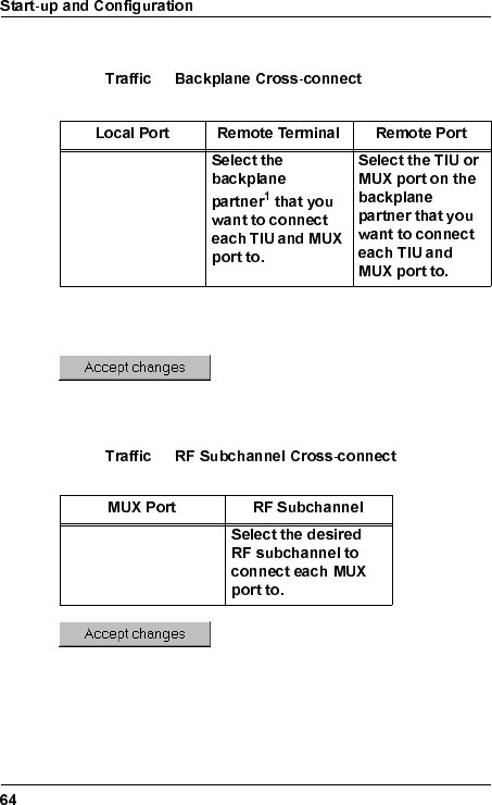
&URVVFRQQHFWLQJ7UDIILF&KDQQHOV
Select → and edit the
following parameters:
&URVVFRQQHFWLQJ5)6XEFKDQQHOV
Select → and edit the
following parameters:
TIU and MUX ports
available for cross-
connection.
1. Numbering of the Indoor Units in the magazine starts at the
bottom of the magazine; unit number 1 is at the bottom and unit
number 2/6 is at the top.
MUX ports available
for cross-connection
across the hop.
WLDM001B
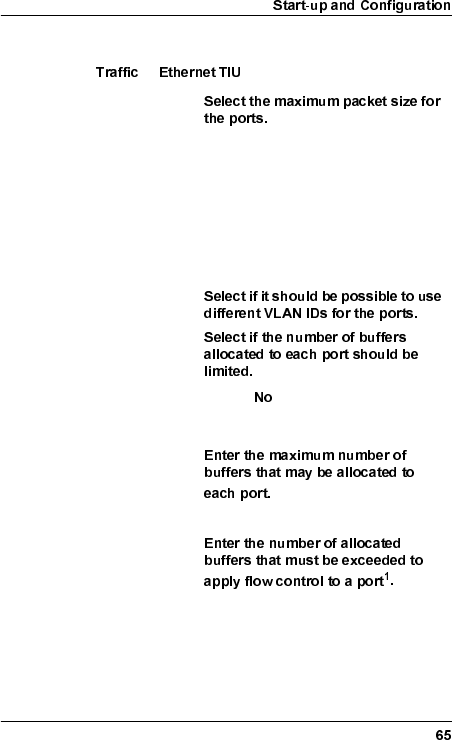
(WKHUQHW7UDIILF3RUWV
Select →and edit the following parameters:
Maximum packet size
Individual port setting: The maximum
packet size is determined by the
"Packet Size" for each individual port
below.
6 kB packet size: The maximum packet
size will be 6 kB. This setting overrides
the "Packet Size" for each individual
port below.
Ethernet VLAN
tagging
Buffer threshold
enabled
If set to , "Maximum buffers
allocated", "XOFF threshold", and
"XON threshold" will be ignored.
Maximum buffers
allocated
1
Default = 160
XOFF threshold
Default = 128
WLDM001B
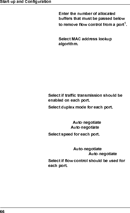
XON threshold
Default = 104
Address lookup
algorithm
Optimized for sequential MAC
addresses
Optimized for random MAC addresses
1. The actual number of buffers is truncated to the nearest lower
multiple of 8.
Port no The Ethernet traffic ports on the front of the
terminal.
Enabled
Duplex
Half duplex/Full duplex/Auto-negotiate.
If you choose , the speed will
be forced to .
Speed
10 Mbit/s, 100 Mbit/s, or Auto-negotiate.
If you choose , the duplex
mode will be forced to .
Flow control
No flow control/Flow control/Auto-negotiate.
WLDM001B
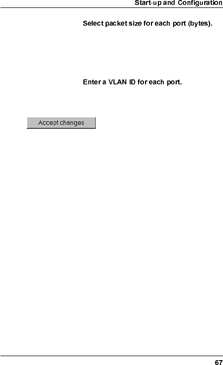
Packet size
1518: Used for most Ethernet types.
1536: Used for VLAN tagging.
This setting may be overridden by "Maximum
packet size" above.
Port VLAN ID
The VLAN ID is only applicable if "Ethernet
VLAN tagging" is enabled above.
WLDM001B
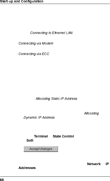
5HPRWH0DQDJHPHQW&RQQHFWLRQ
Connect the radio terminal remotely according to one of the
following alternatives:
•For set-up of a TCP/IP network on an Ethernet LAN, refer to
section below.
•For set-up of a TCP/IP network via a modem, refer to section
on page 70.
•For set-up of a TCP/IP network via an ECC, refer to section
on page 73.
&RQQHFWLQJWR(WKHUQHW/$1
1. Allocate an IP address to the Ethernet port (10baseT) of the
radio terminal in one of the following ways:
– For set-up of a TCP/IP network on an Ethernet LAN using
static IP addresses, allocate a static IP address, subnet
mask and broadcast address to the Ethernet port. Refer to
section on page 78.
– For set-up of a TCP/IP network on an Ethernet LAN using
dynamic IP addresses, configure the Ethernet port to use
dynamic IP addresses. Refer to section
on page 79.
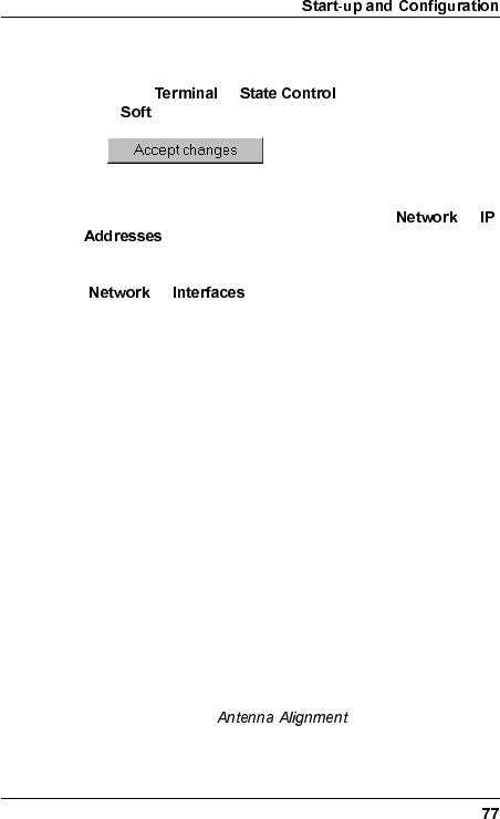
2. Perform a soft restart of the radio terminal for the changes to
take effect:
– Select → and select Restart type
= .
– Wait until the radio terminal is in STANDBY state.
3. Go to the web page "Address Configuration" ( →
) to verify the changes above.
WLDM001B
4. Go to the web page "Network Interface Configuration"
(→ ) and make sure that the status of the
Ethernet port (10baseT) is set to "Up".
5. Exit the web browser and disconnect the serial PC cable
between the local PC and the radio terminal.
6. Make sure the remote management equipment is connected
to the Ethernet LAN network, or to another radio terminal
connected to the Ethernet LAN network, and that it is set up
to work properly in this environment. For further information,
refer to the Operation and Maintenance Manual (WLDM002).
7. Connect the radio terminal to the network by connecting an
UTP cable to the 10baseT port on the BBU.
8. Proceed to section on page 80.
WLDM001B
&RQQHFWLQJYLD0RGHP
1. Allocate an IP address to the serial port (MODEM/NMS 2) of
the radio terminal in one of the following ways:
– For set-up of a TCP/IP network on a modem connection
using static IP addresses, allocate a static IP address,
subnet mask and broadcast address to the serial port
(MODEM/NMS 2). Refer to section
on page 78.
– For set-up of a TCP/IP network on a modem connection
using dynamic IP addresses, configure the serial port
(MODEM/NMS 2) to use dynamic IP addresses. Refer to
section on page 79.
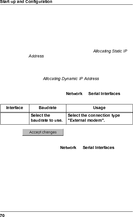
2. Configure the serial port (MODEM/NMS 2) for modem
connection by selecting → and
editing the following parameters:
3. Configure the modem behaviour for the serial port (MODEM/
NMS 2) by selecting →and
editing the following parameters:
– Telephone number;
– Modem mode; and
– Modem idle timeout.
RS-232/2
WLDM001B
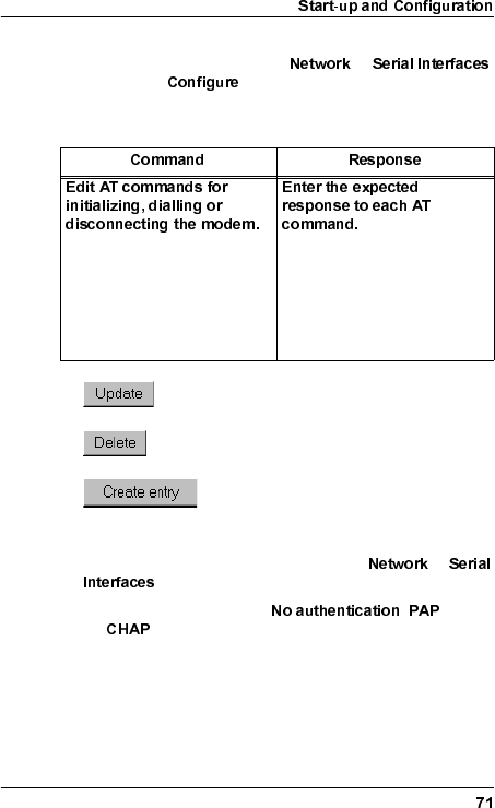
4. Configure the modem AT commands for the serial port
(MODEM/NMS 2) by selecting →
and clicking for the "Initialize sequence", "Dial
sequence" or "Disconnect sequence". Edit the following
parameters:
5. Configure the modem security by selecting →
and editing the following parameters:
– Authentication protocol ( , or
);
– PAP user (if PAP is used);
– PAP password (if PAP is used);
– PAP password confirmation (if PAP is used);
For the dial sequence, the
telephone number will be
automatically added after the
last command provided that
you have entered a value for
"Telephone number" above.
Leave empty if no response is
expected.
Update the database with the new
settings for the AT command.
Delete the AT command in the
database.
Add a new AT command, entered on the
row "Add command", to the database.
WLDM001B
– CHAP secret (if CHAP is used); and
– CHAP secret confirmation (if CHAP is used).
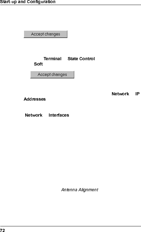
6. Perform a soft restart of the radio terminal for the changes to
take effect:
– Select → and select Restart type
= .
– Wait until the radio terminal is in STANDBY state.
7. Go to the web page "Address Configuration" ( →
) to verify the changes above.
8. Go to the web page "Network Interface Configuration"
(→ ) and make sure that the status of the
serial port (MODEM/NMS 2) is set to "Up".
9. Exit the web browser and disconnect the serial PC cable
between the local PC and the radio terminal.
10. Make sure the remote management equipment is connected
to a remote modem, and that it is set up to work properly in its
environment. For further information, refer to the Operation
and Maintenance Manual (WLDM002).
11. Connect the radio terminal to a modem by using the serial
port (MODEM/NMS 2) on the BBU.
12. Proceed to section on page 80.
WLDM001B
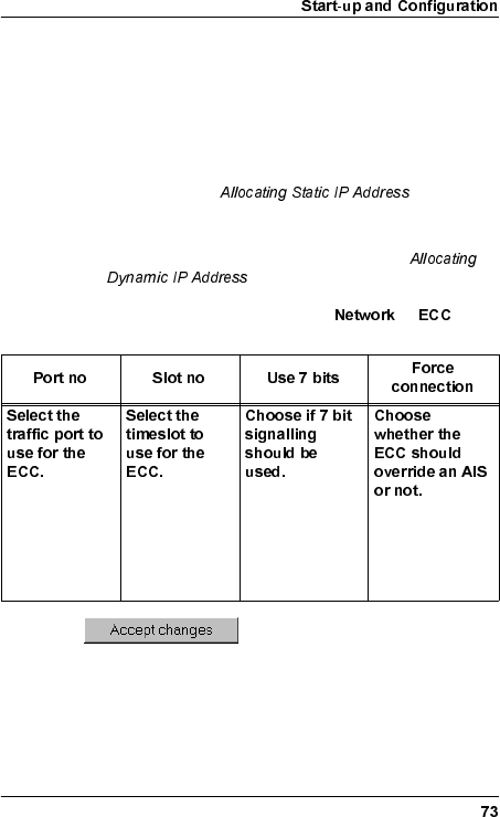
&RQQHFWLQJYLD(&&
1. Allocate an IP address to the ECC port of the radio terminal in
one of the following ways:
– For set-up of a TCP/IP network on a ECC connection
using static IP addresses, allocate a static IP address,
subnet mask and broadcast address to the ECC port.
Refer to section on page 78.
– For set-up of a TCP/IP network on a ECC connection
using dynamic IP addresses, configure the ECC port to
use dynamic IP addresses. Refer to section
on page 79.
2. Configure the ECC port by selecting → and
editing the following parameters:
Traffic ports
available for an
ECC are E1:1–
17, DS1:1–17,
and OH:1–2.
0–31 (E1)
0–23 (DS1)
Yes: The 7 most
significant bits
will be used.
No: All 8 bits will
be used.
WLDM001B
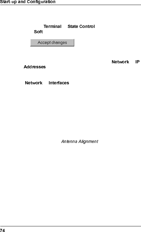
3. Perform a soft restart of the radio terminal for the changes to
take effect:
– Select → and select Restart type
= .
– Wait until the radio terminal is in STANDBY state.
4. Go to the web page "Address Configuration" ( →
) to verify the changes above.
5. Go to the web page "Network Interface Configuration"
(→ ) and make sure that the status of the
ECC port is set to "Up".
6. Exit the web browser and disconnect the serial PC cable
between the local PC and the radio terminal.
7. Make sure the remote management equipment is connected
to the ECC, and that it is set up to work properly in its
environment. For further information, refer to the Operation
and Maintenance Manual (WLDM002).
8. Proceed to section on page 80.
WLDM001B
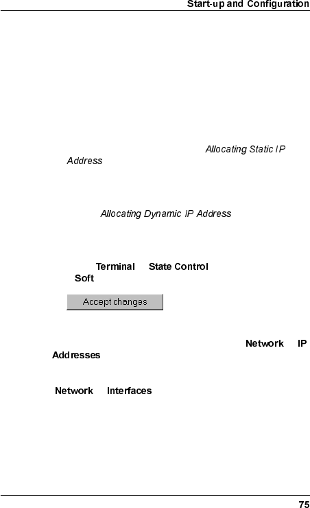
&RQQHFWLQJYLDD&RPPRQ%DFNSODQH
Connection of the radio terminal via a common backplane
requires that it has been mounted in a 2U or 6U Magazine.
1. Allocate an IP address to the backplane port in question in
one of the following ways:
– For set-up of a TCP/IP network on a backplane
connection using static IP addresses, allocate a static IP
address, subnet mask and broadcast address to the
backplane port. Refer to section
on page 78.
– For set-up of a TCP/IP network on a backplane
connection using dynamic IP addresses, configure the
backplane port to use dynamic IP addresses. Refer to
section on page 79.
2. Perform a soft restart of the radio terminal for the changes to
take effect:
– Select → and select Restart type
= .
– Wait until the radio terminal is in STANDBY state.
3. Go to the web page "Address Configuration" ( →
) to verify the changes above.
4. Go to the web page "Network Interface Configuration"
(→ ) and make sure that the status of the
backplane port in question is set to "Up".
5. Exit the web browser and disconnect the serial PC cable
between the local PC and the radio terminal.
6. Make sure the remote manager is connected to the
management network, and that it is set up to work properly in
WLDM001B
its environment. For further information, refer to the Operation
and Maintenance Manual (WLDM002).
7. Proceed to section on page 80.
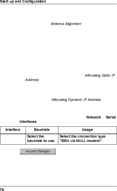
'DLV\FKDLQLQJ
1. Allocate an IP address to the serial port (LM/NMS 1 or
MODEM/NMS 2) of the radio terminal in one of the following
ways:
– For set-up of a TCP/IP network on a daisy chain using
static IP addresses, allocate a static IP address, subnet
mask and broadcast address to the serial port (LM/NMS 1
or MODEM/NMS 2). Refer to section
on page 78.
– For set-up of a TCP/IP network on a daisy chain using
dynamic IP addresses, configure the serial port (LM/
NMS 1 or MODEM/NMS 2) to use dynamic IP addresses.
Refer to section on page
79.
2. Configure the serial port (LM/NMS 1 or MODEM/NMS 2) for
connection to a radio terminal by selecting →
and editing the following parameters:
3. Make sure the serial port (LM/NMS 1 or MODEM/NMS 2) on
the radio terminal to connect to has been configured for
connection to a radio terminal as well.
RS 232/1 or
RS 232/2
WLDM001B
4. Perform a soft restart of the radio terminal for the changes to
take effect:
– Select → and select Restart type
= .
– Wait until the radio terminal is in STANDBY state.
5. Go to the web page "Address Configuration" ( →
) to verify the changes above.
6. Go to the web page "Network Interface Configuration"
(→ ) and make sure that the status of the
serial port (LM/NMS 1 or MODEM/NMS 2) is set to "Up".
7. Exit the web browser and disconnect the serial PC cable
between the local PC and the radio terminal.
8. Make sure the remote manager is connected to the
management network, and that it is set up to work properly in
its environment. For further information, refer to the Operation
and Maintenance Manual (WLDM002).
9. Connect the radio terminal to the other radio terminal by using
the serial port (LM/NMS 1 or MODEM/NMS 2) on the BBU.
– For an LM/NMS 1–MODEM/NMS 2 connection, use a
straight-through serial cable with one 9 pin D-SUB plug
and one 9 pin D-SUB jack.
– For an LM/NMS 1–LM/NMS 1 connection, use a null
modem cable with two 9 pin D-SUB plugs.
– For a MODEM/NMS 2–MODEM/NMS 2 connection, use a
null modem cable with two 9 pin D-SUB jacks.
10. Proceed to section on page 80.
WLDM001B
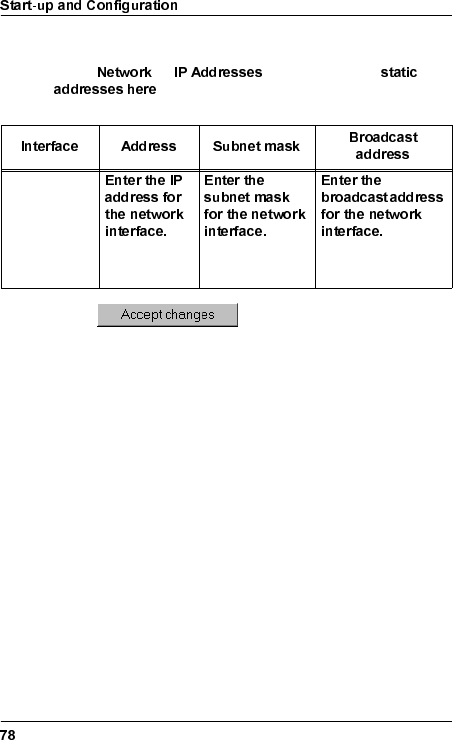
$OORFDWLQJ6WDWLF,3$GGUHVV
Select → and follow the link
. Edit the following parameters for the interface
in question:
For further information on static IP addresses, refer to the
Operation and Maintenance Manual (WLDM002).
Management
network
interface.
Default =
255.255.255.0 Default =
255.255.255.255
WLDM001B
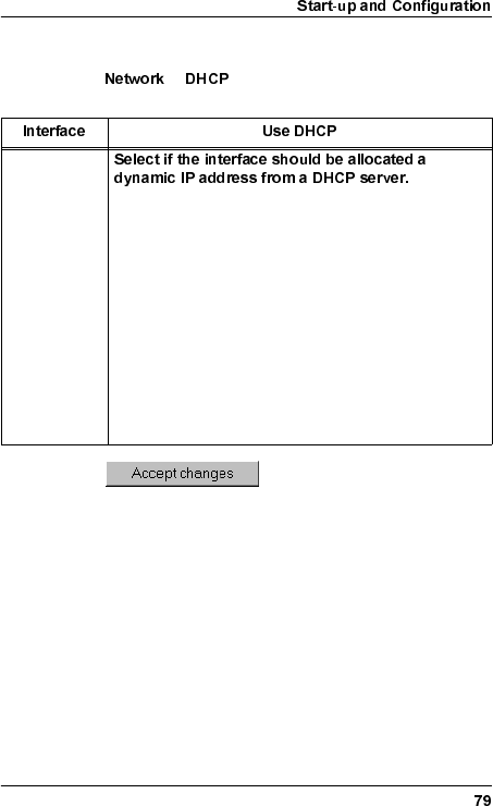
$OORFDWLQJ'\QDPLF,3$GGUHVV
Select → and edit the following parameter for the
interface in question:
Management
network
interface. No: DHCP will not be used.
Yes, send request on all interfaces: The DHCP request
will be sent on all interfaces. Use this alternative if only
one DHCP server is present in the network, and if you
are not sure which path the DHCP request may follow
to the DHCP server.
Yes, send request on this interface: The DHCP request
will be sent on this interface only. Use this alternative if
the DHCP server that you want to use is connected
towards this interface, and you want to be sure that the
DHCP request does not reach a DHCP server
connected towards any of the other interfaces.
WLDM001B
$QWHQQD$OLJQPHQW
7RROV5HTXLUHGIRU$QWHQQD$OLJQPHQW
•17 mm torque wrench
•Voltmeter (0–5V DC) with BNC adapter (the AGC contact on
the RFU is of BNC socket type).
3UHSDUDWLRQV
1. Check that all relevant instructions in the preceding sections
of this manual are completed for both installation sites before
you start aligning the antennas.
2. Arrange for speech communication between the installation
sites if possible. This will make it easier to align the antennas
correctly.
WLDM001B
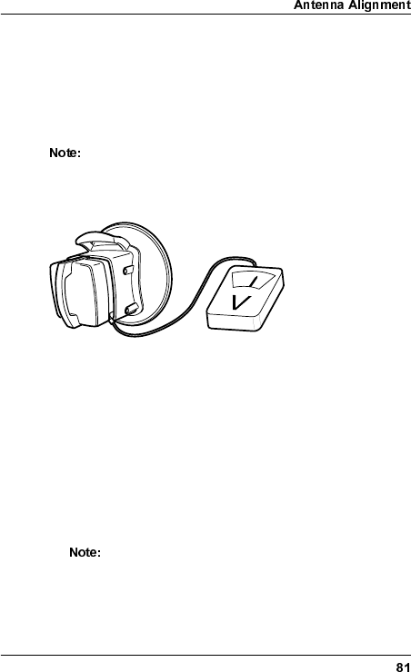
$OLJQPHQW3URFHGXUH
When aligning the antennas, the AGC port on the RFU (BNC
connector) is used to indicate the Received Signal Level (RSL).
Use a standard multimeter with a BNC adapter to measure the
AGC voltage. The AGC voltage is somewhere in the range 0–5V
DC.
The alignment procedure should be performed for one
antenna at a time. If the initial alignment error is large,
however, you may need to begin by moving both
antennas to achieve contact.
1. Connect the voltmeter to the AGC port on the RFU.
The voltmeter will always show a value of at least 0.5V if the
radio terminal is working correctly.
If the antenna is receiving an unknown signal, or a signal from
a radio terminal which has the wrong security code, the
voltmeter will show an oscillating value.
2. Maximize the voltmeter value by using the azimuth and
elevation screws to adjust the antenna. The maximum
possible adjustment is ±20 degrees in both azimuth and
elevation.
If the alignment error is more than approximately 4
degrees, there is a risk that the maximum AGC
voltage that you have found is for a side lobe. The
maximum value of the AGC voltage is lower for a side
lobe than for the main lobe.
WLDM001B
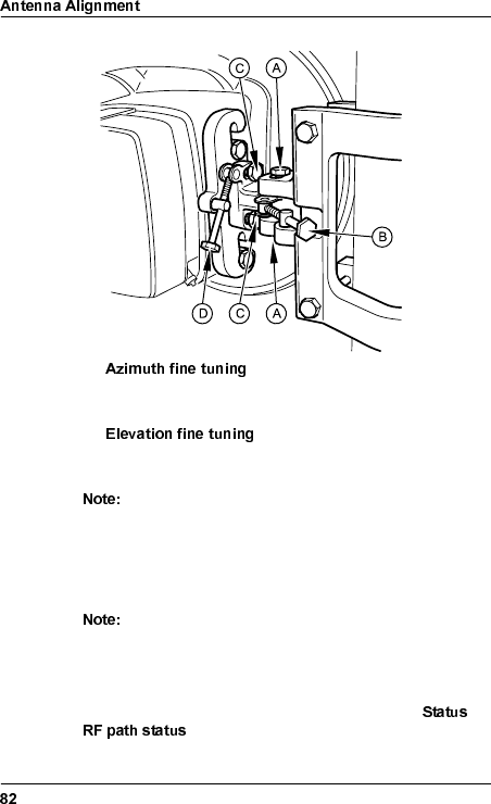
–Loosen the two locking screws (A).
Use the azimuth screw (B) to adjust the antenna.
–Loosen the two locking screws (C).
Use the elevation screw (D) to adjust the antenna.
Do not loosen the locking screws too much. There
should be a slight friction when aligning the antenna.
3. Use the torque wrench to secure the antenna position by
tightening the locking screws for both azimuth and elevation.
These are indicated in the figure above (A and C).
The torque should be 35 Nm ± 10% when tightening
the screws. The azimuth and elevation screws must
not be touched after the locking screws have been
tightened.
4. Check the RSL on the web page "RF Path Status" ( →
) of the Indoor Unit and record the value.
WLDM001B
,QVWDOODWLRQ9HULILFDWLRQDQG7HVW
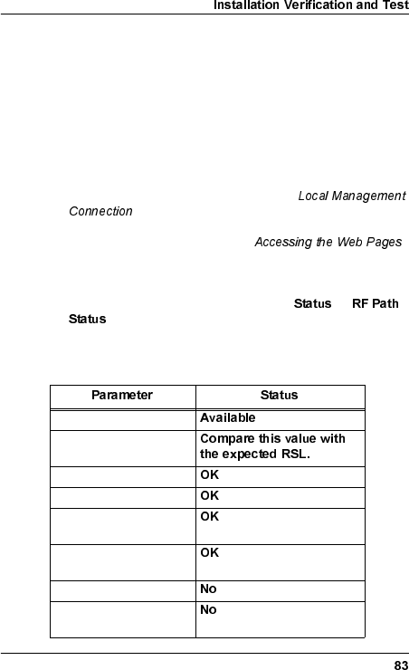
&KHFNLQJ5)3DWK6WDWXV
1. Make sure that all relevant instructions in the preceding
sections have been performed for both installation sites.
2. Make sure that your PC is connected to one of the radio
terminals in the hop according to section
on page 49.
3. Follow the instructions in section
on page 60 to access the web pages for one of the radio
terminals.
4. Access the web page "RF Path Status" ( →
).
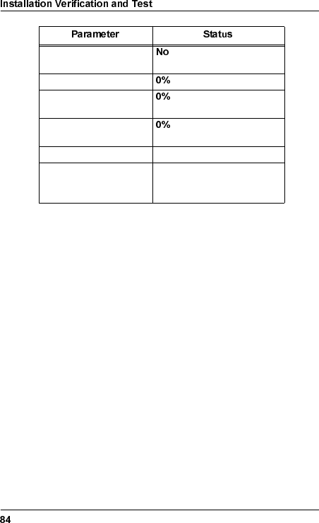
5. Check that all status values are in accordance with the table
below:
RF Path Availability
Received Signal Level
Security Code
Modem Phase Lock
Modem Bit
Synchronization
MUX Bit
Synchronization
Last Second Errored
Last Second Severely
Errored
WLDM001B
6. Repeat step 3–5 above for the radio terminal at the far end of
the hop.
Background Block Error
during last second
Errored Second Rate
Severely Errored
Second Rate
Background Block Error
Rate
RF Present Yes
RF Measured Power Compare this value with the
configured TX Output
Power.

WLDM001B
,QGH[
1XPHULFV
1 ft. antenna ...............................13
19" rack
Installation Kit for...................17
mounting the Indoor Unit in ...25
2 ft. antenna ...............................13
26 pin D-SUB connector ............19
2U Magazine..............................18
Installation Kit for...................18
space requirements...............10
6U Magazine..............................18
Installation Kit for...................18
space requirements...............10
9 pin D-SUB connector
modem ..................................19
PC .........................................19
$
accessories
indoor ....................................18
product numbers .....................5
ACTIVE LED ..............................47
AGC port ....................................81
contact type...........................80
AGC voltage...............................81
ALARM LED...............................47
alignment ...................................80
error.......................................81
amr.inf .................................. 44, 50
ANSI standard..............................6
Antenna Unit ..............................34
1 ft. ........................................13
2 ft. ........................................13
alignment...............................80
integrating with RFU..............36
left or right side mounting......37
mounting ......................... 13, 39
moving coaxial connector .....35
product numbers.....................5
Antenna/RF Unit
grounding..............................40
left or right side mounting......37
lifting......................................37
mounting ...............................39
recommended mounting .......38
AT commands ...........................71
azimuth
fine tuning .............................82
screw.....................................81
%
background block error..............84
background block error rate.......84
backplane
connection set-up..................75
cross connect conf................64
balanced interface ............... 20, 22
connector mounting ..............28
bandwidth ..................................62
Baseband Unit ...........................17
product numbers.....................5
BBU, see Baseband Unit
beryllium oxide.............................8
BNC adapter..............................80
brackets .....................................25
broadcast address allocation.....78
&
captive nut
magazine ..............................18
rack mount ............................17
CHAP.........................................72

WLDM001B
common backplane connection .75
configuration
local management .................49
radio terminal.........................58
remote management .............68
connecting the power cable .......48
connector
26 pin D-SUB for ext. I/O. 17, 31
37 pin D-SUB for traffic .........29
9 pin D-SUB for traffic ...........30
DC power ........................ 17, 32
mounting................................28
N type.............................. 33, 40
TNC ................................. 17, 33
contact person ...........................61
control panel ..............................19
copper braid.............. 11, 14, 27, 40
cross connect.............................59
RF subchannels ....................59
traffic channels ......................59
'
daisy-chaining
connection set-up ..................76
equipment..............................46
DC connector.............................19
Dial Up Networking
software.................................44
Windows 95/98................ 53, 57
Windows NT.................... 52, 57
dialling up
configuration..........................52
serial port...............................57
documentation .............................5
domain name .............................61
D-SUB connector
26 pin for external I/O.17, 19, 31
37 pin for traffic channel ........29
9 pin for modem ....................19
9 pin for OH channel .............31
9 pin for PC ...........................19
9 pin for traffic channel..........30
DC power..............................32
dynamic IP addresses ...............79
(
ECC connection set-up..............73
electrical safety............................9
electromagnetic interference
indoor ....................................11
outdoor..................................14
elevation
fine tuning .............................82
screw.....................................81
EMC
indoor ....................................11
outdoor..................................14
environment
indoor requirements..............12
outdoor requirements............15
errored second ..........................83
errored second rate ...................84
Ethernet
DTE.......................................19
Ethernet for management
cable .....................................45
connection set-up..................68
interfaces ..............................19
Ethernet TIU
buffers...................................65
configuration .........................65
connectors, mounting............30
duplex mode .........................66
enable ...................................66
flow control............................66
interfaces ........................ 20, 23

WLDM001B
MAC address lookup.............66
packet size ...................... 65, 67
speed.....................................66
VLAN ............................... 65, 67
ETS 300 019........................ 12, 15
ETS 300 385........................ 11, 14
ETSI rack mounting kit...............18
external I/O connector.......... 17, 31
*
grounding
Antenna/RF Unit.............. 14, 40
indoor equipment...................11
Indoor Unit....................... 19, 27
M10 screw holes for ........ 14, 40
M6 lug for ........................ 11, 27
outdoor equipment ................14
radio cable....................... 14, 41
requirements ...........................9
+
horizontal polarization................35
hostname ...................................61
humidity
indoor ....................................12
outdoor ..................................15
HyperTerminal ..................... 42, 44
,
I/O port .......................................19
indoor
accessories ...........................18
equipment..............................17
requirements .........................10
indoor radio cable ......................33
Indoor Unit .................................17
EMC ......................................11
grounding........................ 11, 27
installation.............................16
installing the cables for .........28
mounting ...............................24
mounting in 19" rack .............25
mounting in magazine...........26
numbering in magazine.........26
space requirements ..............10
initial configuration.....................58
installation
indoor ....................................16
outdoor..................................34
verification.............................83
Installation Kit
for 19" rack............................17
for 2U Magazine....................18
for 6U Magazine....................18
Installation Manual.......................5
interfaces
balanced ......................... 20, 22
co-directional.........................31
Ethernet TIU.................... 20, 23
unbalanced ..................... 20–21
internal protection circuits..........11
IP addresses
allocation...............................78
dynamic.................................79
static......................................78
ITU standard................................6
ITU-T G.703......................... 20, 31
/
LAN............................................45
LEDs..........................................19
blinking pattern......................47
lightning protection .............. 38, 41
LM/NMS1 port ...........................19

WLDM001B
local management......................49
equipment..............................44
locking screw .............................37
login ...........................................60
0
M10 grounding screw holes . 14, 40
M10 screws................................37
M6 grounding lug ............11, 19, 27
magazine
2U..........................................18
2U Installation Kit ..................18
6U..........................................18
6U Installation Kit ..................18
mounting of............................26
Mounting Rail for ...................18
Mounting Rail Screw for ........18
mounting the Indoor Unit in ...26
numbering of Indoor Units .....26
space requirements...............10
transport safety panels..........26
main lobe ...................................81
management
backplane connection............75
daisy-chaining .......................76
direct connection, static.........55
ECC connection ....................73
Ethernet connection ..............68
local.......................................49
modem connection.....70, 75–76
remote ...................................68
Mast Mounting Bracket ..............34
fastening to mast...................38
mast requirements .....................13
mast stability ..............................13
Metral connector ........................20
modem .......................................45
AT commands .......................71
authentication........................71
bit synchronization status......83
cable .....................................45
connection set-up..................70
dial sequence........................71
disconnect sequence ............71
driver for null modem ............50
idle timeout............................70
initialize sequence.................71
mode .....................................70
telephone number.................70
MODEM/NMS2 port...................19
modular connector.....................19
moisture protection ....................36
mounting pole diameter .............13
Mounting Rail.............................18
Screw ....................................18
muting the TX ............................62
MUX
bit synchronization status......83
port........................................59
1
N connector ......................... 33, 40
null modem driver ......................50
2
OH channel connector
9 pin D-SUB for OH ..............31
OH channels, see traffic channels
operating system for PC ............44
Operation and Maintenance ........5
operational modes .....................47
operational states ......................47
outdoor
EMC ......................................14
equipment .............................34

WLDM001B
installation .............................34
requirements .........................13
outdoor radio cable
grounding ..............................41
installation .............................40
maximum length....................40
output power ..............................62
measured ..............................84
3
PAP............................................71
password....................................60
changing................................60
PCcable......................................44
connection .............................55
serial port configuration .........49
setting up...............................49
phase lock
status for Baseband Unit.......83
polarization.................................36
choosing ................................35
power
cable.................................. 9, 32
consumption..........................11
DC connector .............17, 19, 32
indoor requirements ..............11
outdoor requirements ............14
output level configuration ......62
supply .............................. 11, 48
PPP network
dialling up ..............................57
dialling up configuration.........52
set-up of ................................55
Product List..................................5
product numbers
accessories ....................... 5, 18
Antenna Unit...................... 5, 34
Baseband Unit .................. 5, 17
Radio Frequency Unit ....... 5, 34
Traffic Interface Unit..... 5, 21–23
product range ..............................5
protection circuits.......................11
5
Rack Mount Captive Nut...... 17–18
Rack Mount Screw .............. 17–18
radio cable
grounding........................ 14, 41
indoor mounting ....................33
maximum length....................40
outdoor mounting..................40
Radio Frequency Unit................34
BBU connection status..........84
integrating with Antenna Unit 36
mounting ...............................13
product numbers.....................5
remote management .................68
equipment ....................... 45–46
requirements
indoor ....................................10
indoor environment ...............12
indoor power .........................11
indoor space .........................10
mast ......................................13
outdoor..................................13
outdoor environment.............15
outdoor power .......................14
outdoor space .......................13
safety ......................................7
site ..........................................7
RF channel
availability .............................83
configuration .........................62
measured power ...................84
number..................................62

WLDM001B
status.....................................83
RF frame format.........................62
RF subchannel cross connect....64
RFU, see Radio Frequency Unit
RG213 cable ..............................40
RG214 cable ..............................40
RG400 cable ..............................33
RJ-45 connector.........................19
router..........................................45
RS-232
DCE.......................................19
DTE .......................................19
RSL............................................81
checking ................................82
expected................................62
status.....................................83
6
safety
devices ....................................8
electrical ..................................9
precautions..............................7
requirements ...........................7
warnings ..................................7
screw
azimuth..................................81
elevation ................................81
locking ...................................37
magazine...............................18
mounting rail..........................18
rack mount.............................17
security code..............................81
configuration..........................62
status.....................................83
serial port
baudrate .......................... 70, 76
connection type ............... 70, 76
dialling up ..............................57
dialling up configuration ........52
modem connection..... 70, 75–76
PC configuration ...................49
PC connection, static ............55
radio terminal connection......76
settings..................................49
severely errored second ............83
severely errored second rate.....84
side lobe ....................................81
site requirements .........................7
Sofix connector..........................20
space requirements
indoor ....................................10
outdoor..................................13
start-up and configuration..........42
equipment for........................44
static IP address ........................78
allocating to serial port ..........55
subnet mask allocation ..............78
surge arrester ...................... 33, 41
switching
OFF.......................................48
ON.........................................48
syntax ..........................................6
system information conf.............61
7
TCP/IP network
set-up .............. 68, 70, 73, 75–76
Technical Description ..................5
temperature
indoor ....................................12
outdoor..................................15
terminal
ID ..........................................61
location..................................61
TEST LED .................................47
text terminal ...............................44

WLDM001B
TIU, see Traffic Interface Unit
TNC connector................17, 19, 33
tools
for indoor installation .............16
for outdoor installation...........34
torque wrench ...................... 34, 80
traffic channels
configuration..........................63
connecting to backplane........63
connecting to MUX ................63
connectors....................... 29–30
Traffic Interface Unit............. 17, 20
balanced................................22
balanced, cables for ..............28
balanced, connecting ............28
Ethernet.................................23
Ethernet, connecting .............30
mounting................................20
port ........................................59
product numbers .....................5
unbalanced............................21
unbalanced, connecting ........28
traffic interfaces..........................20
traffic routing ..............................59
transients
preventing transmission of ....48
transmitter
frequency...............................62
muting....................................62
output power..........................62
transport safety panels...............26
TX/RX signal definition...............28
8
unbalanced interface............ 20–21
connector mounting...............28
username...................................60
UTP cable ..................................45
9
vertical polarization....................35
VLAN ................................... 65, 67
voltage
hazards ...................................8
supply....................................11
voltmeter.............................. 80–81
:
WARNING LED .........................47
web browser ..............................44
web pages
accessing ..............................60
backplane cross connect ......64
choosing................................60
Ethernet TIU configuration ....65
RF channel configuration ......62
RF path status.......................83
RF subchannel cross con. ....64
system information conf........61
traffic channel configuration..63

WLDM001B