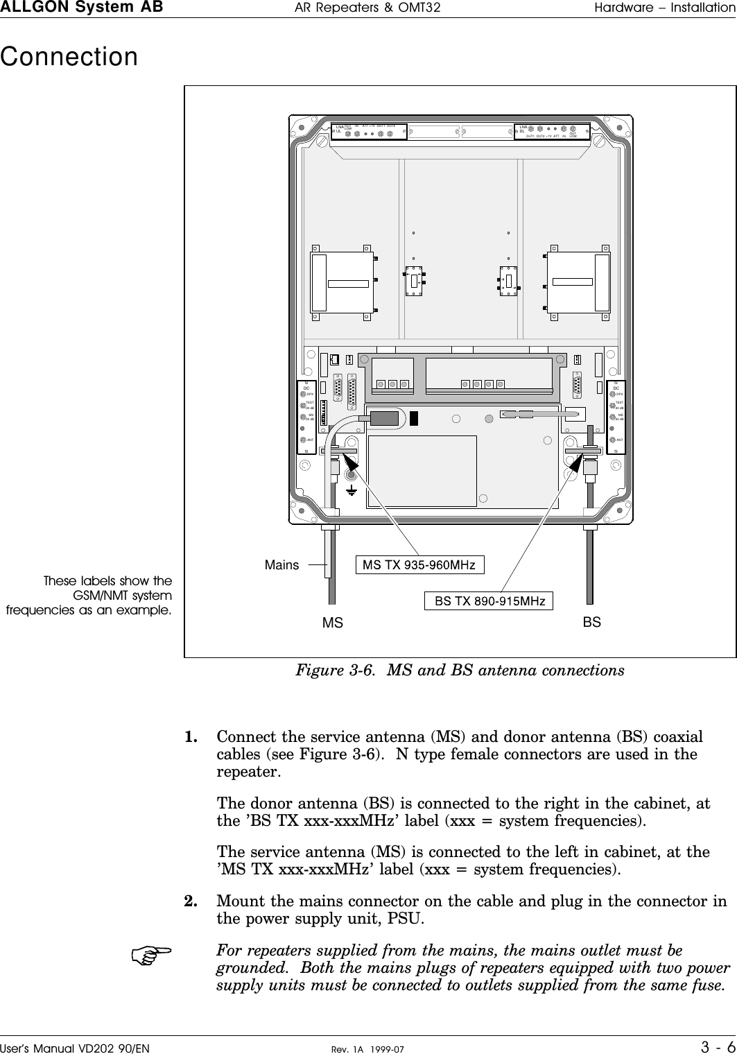
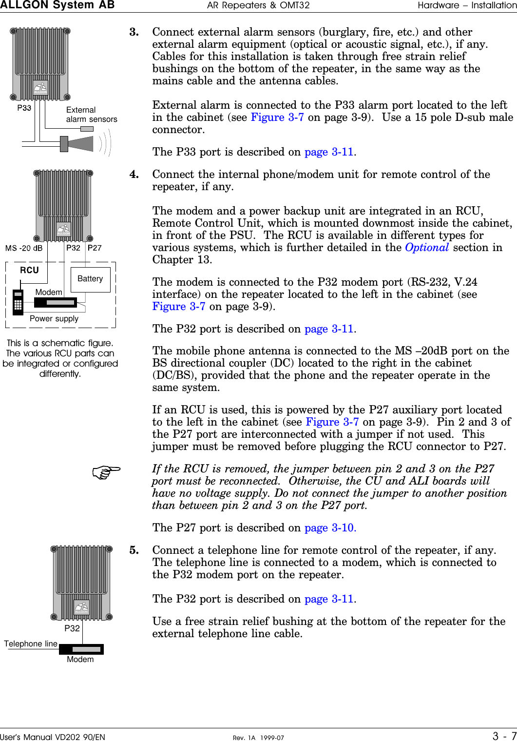
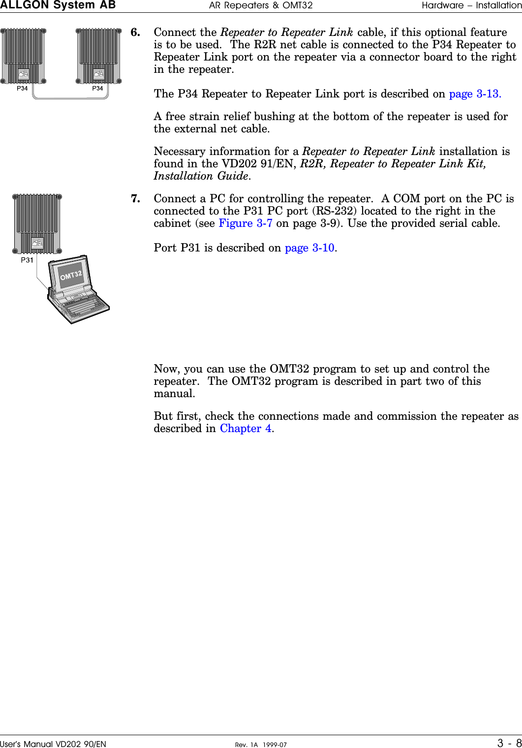
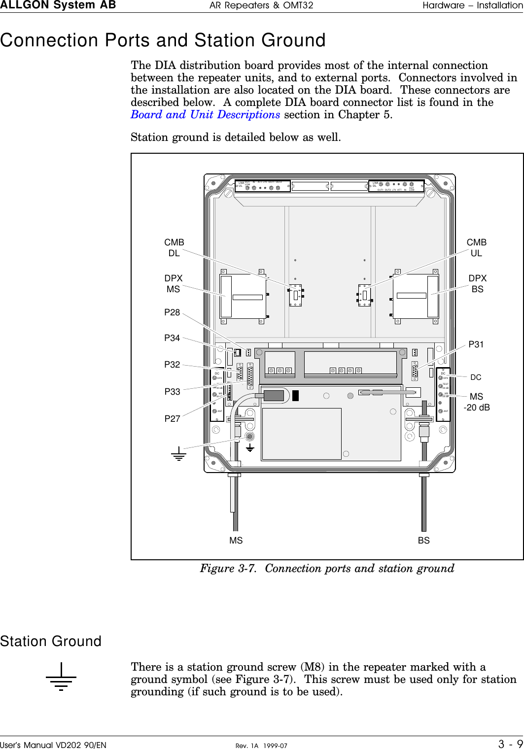
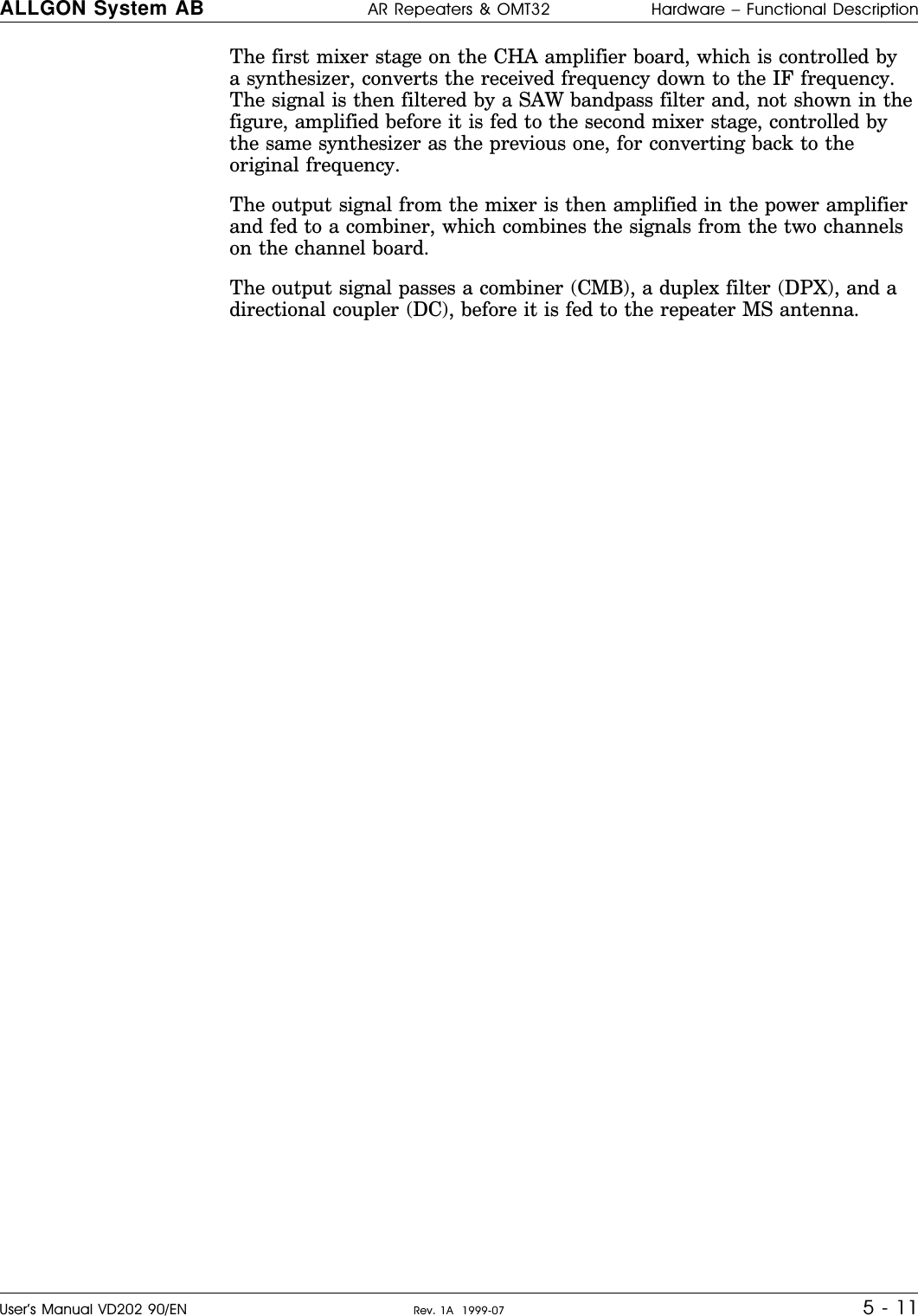
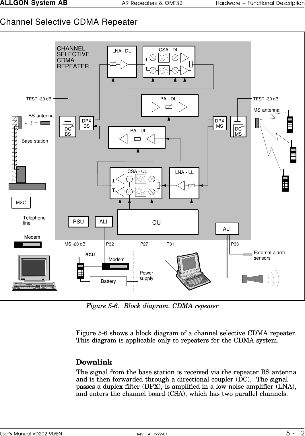
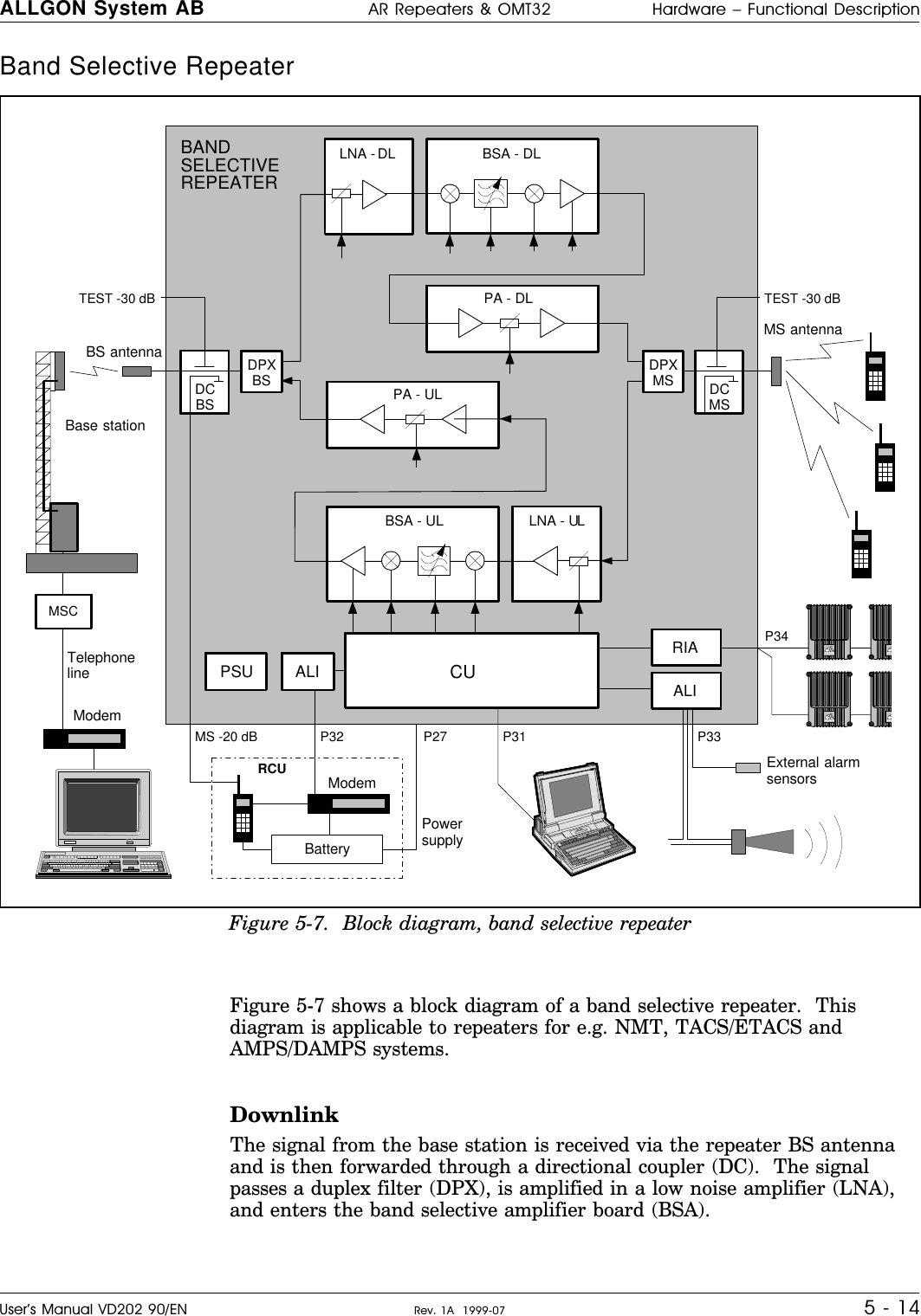
Powerwave Technologies AR3530 PCS Channel Selective Repeater User Manual AR Repeater OMT32 User s Manual
Powerwave Technologies Inc. PCS Channel Selective Repeater AR Repeater OMT32 User s Manual
Contents
- 1. users manual
- 2. New notated manual per request
- 3. original manual
users manual
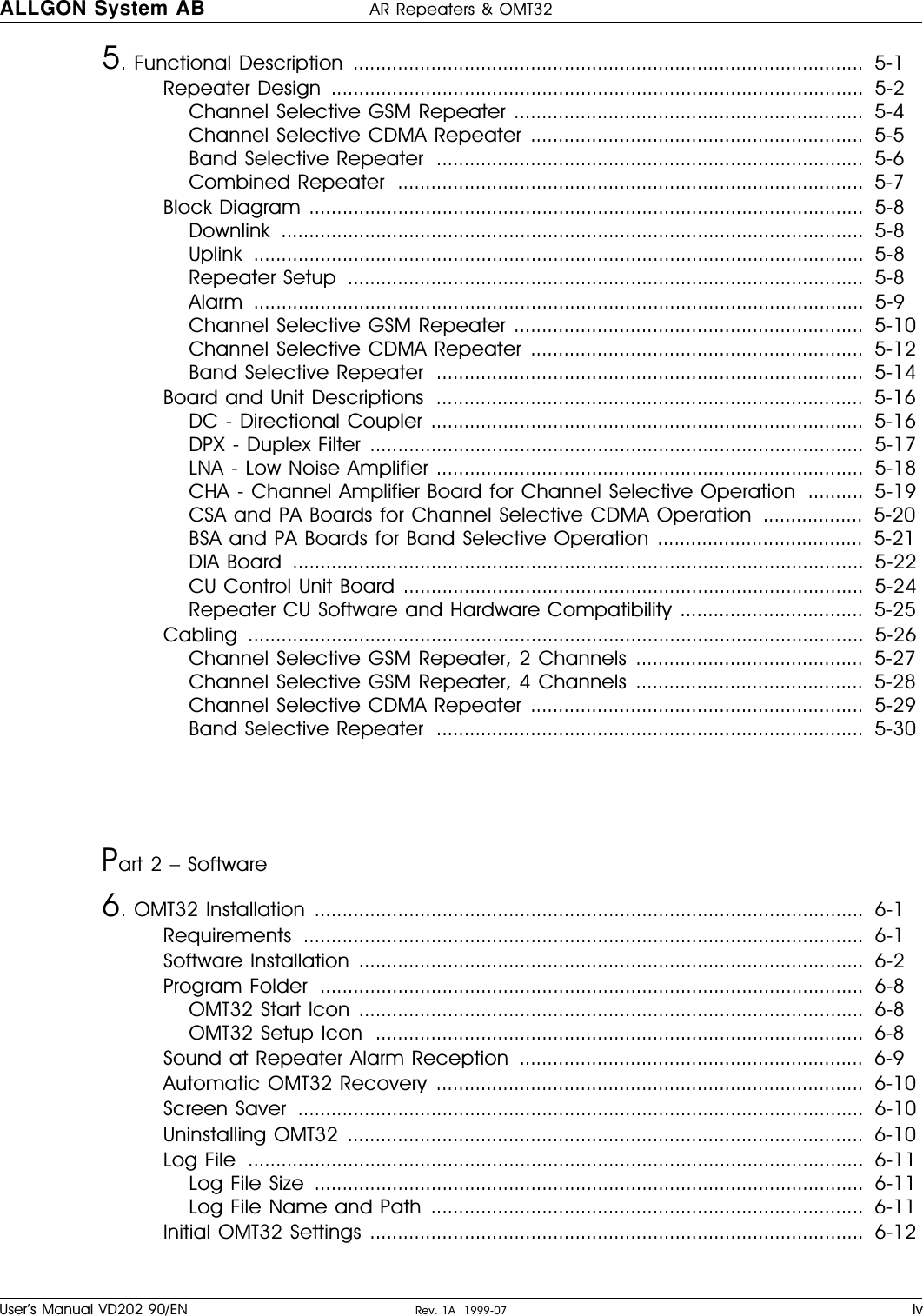
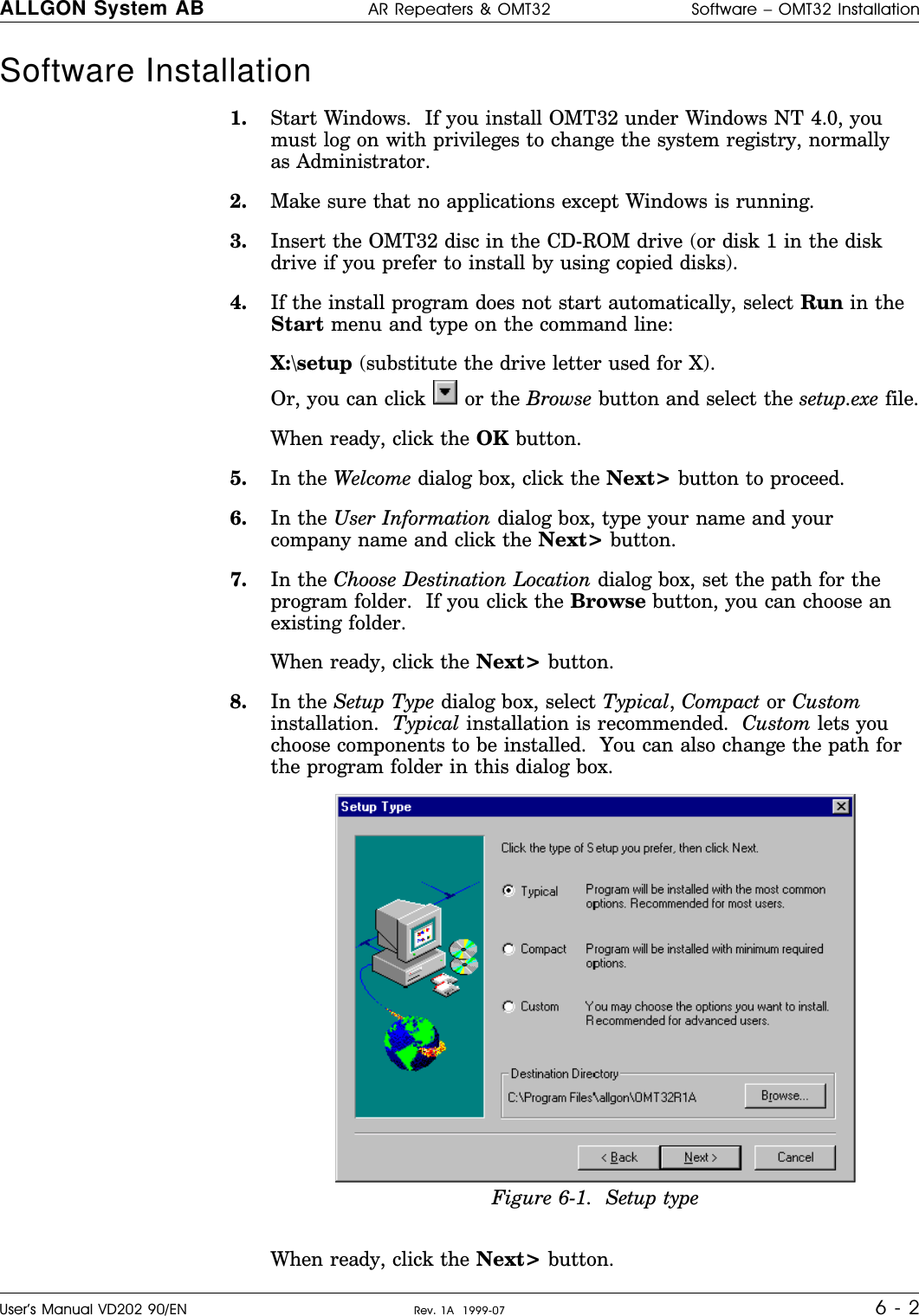
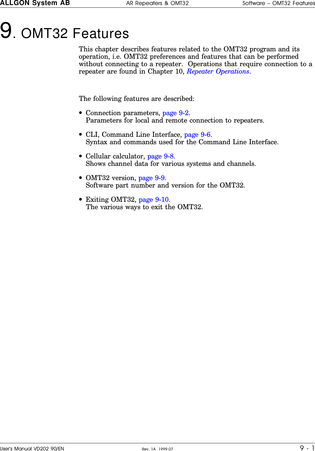
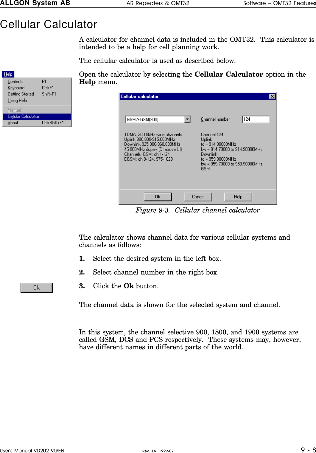
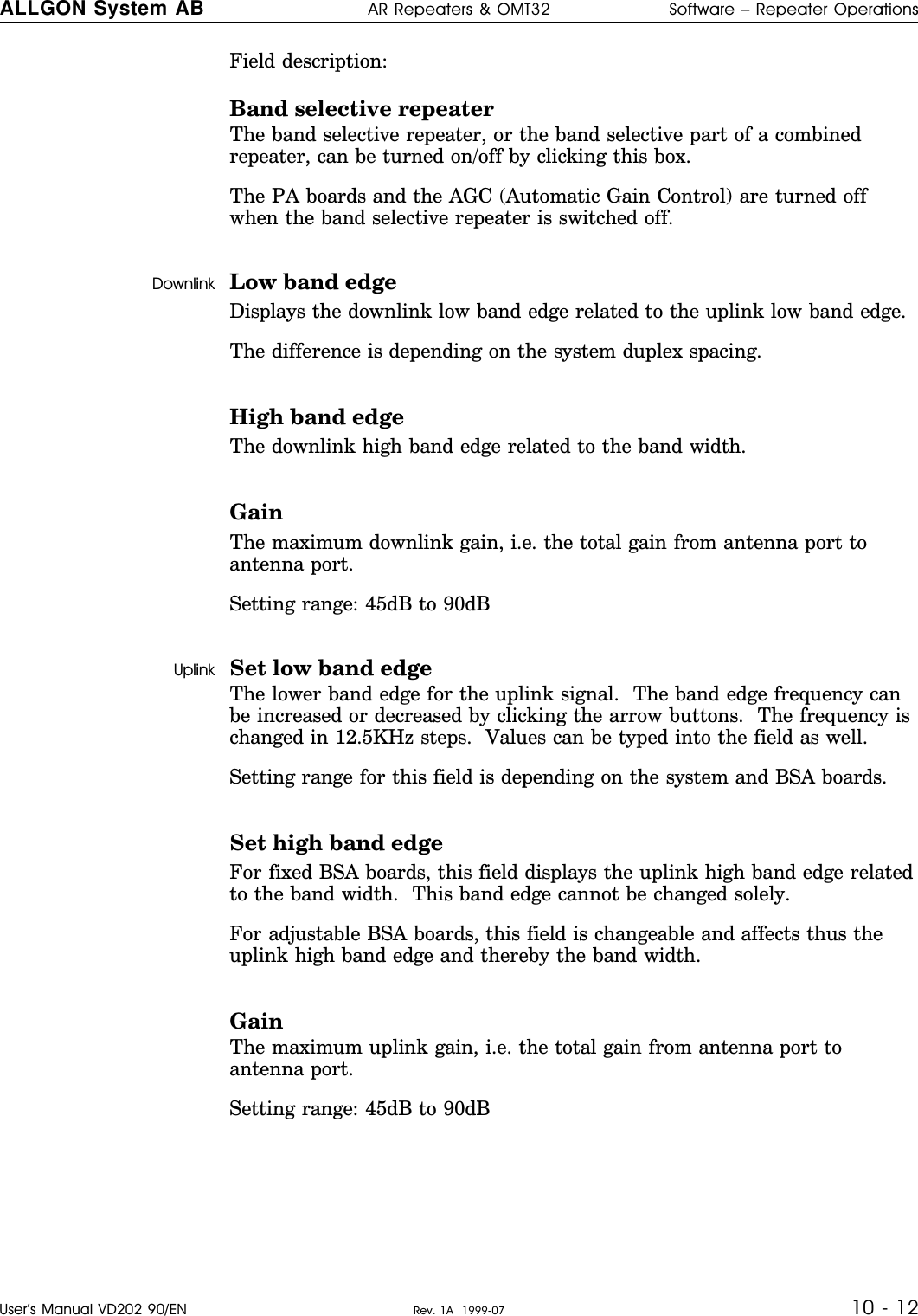
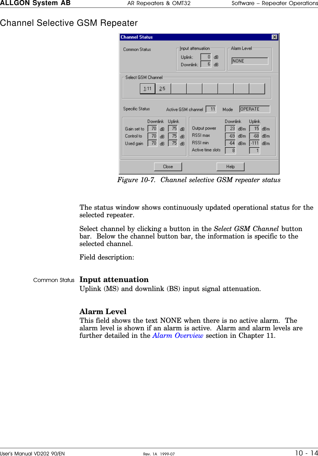
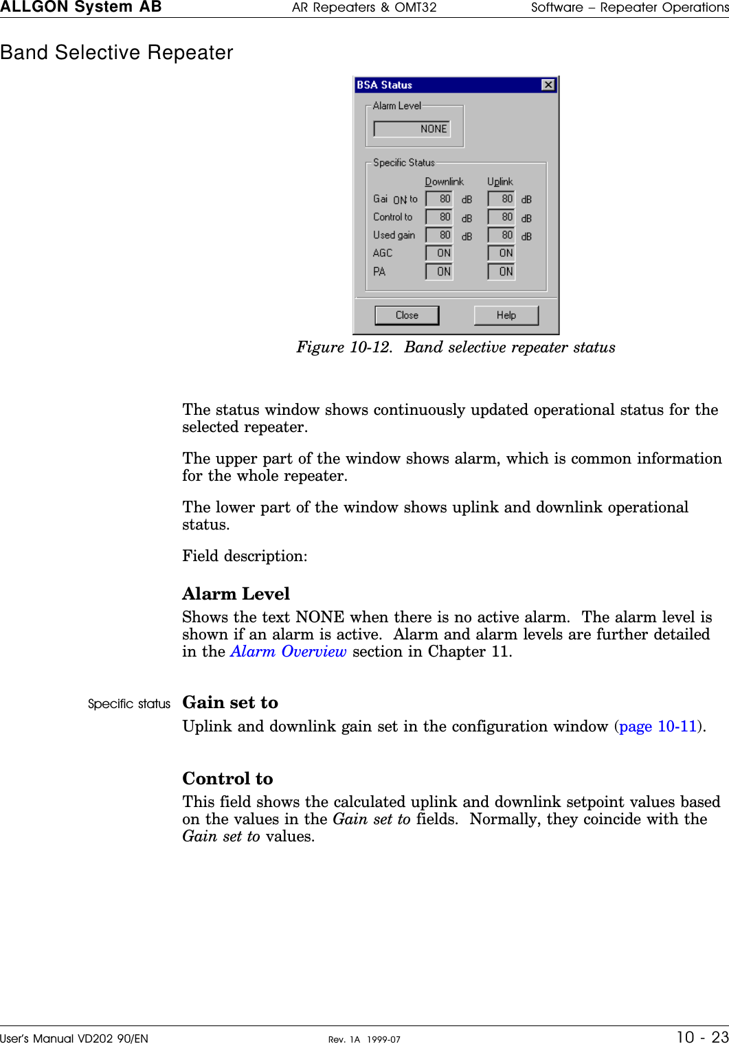
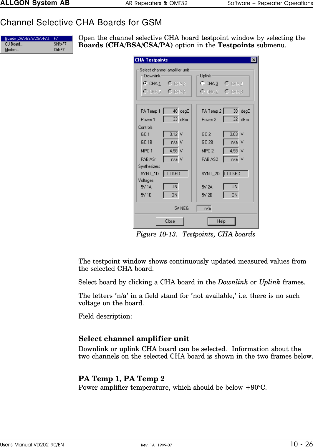
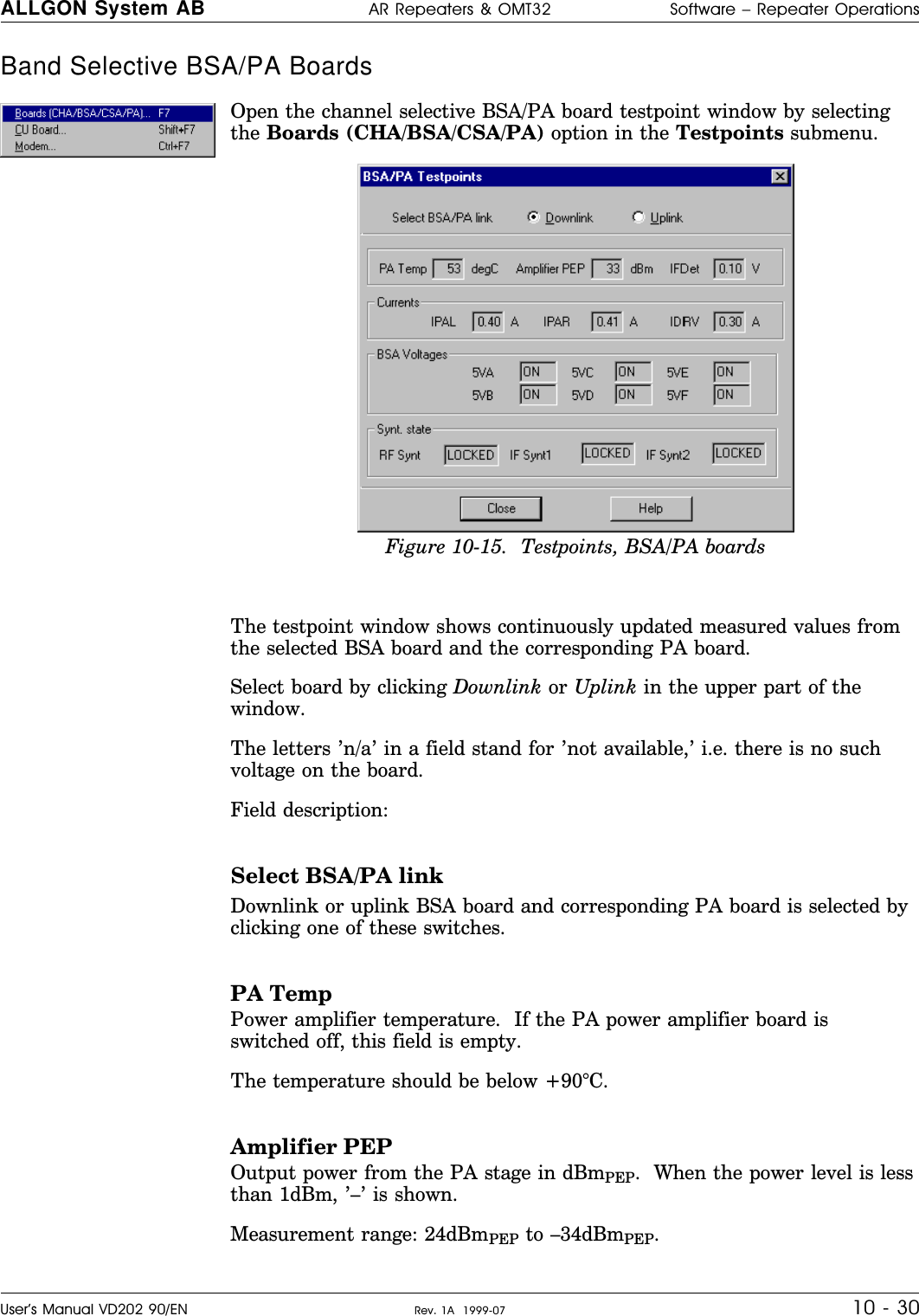
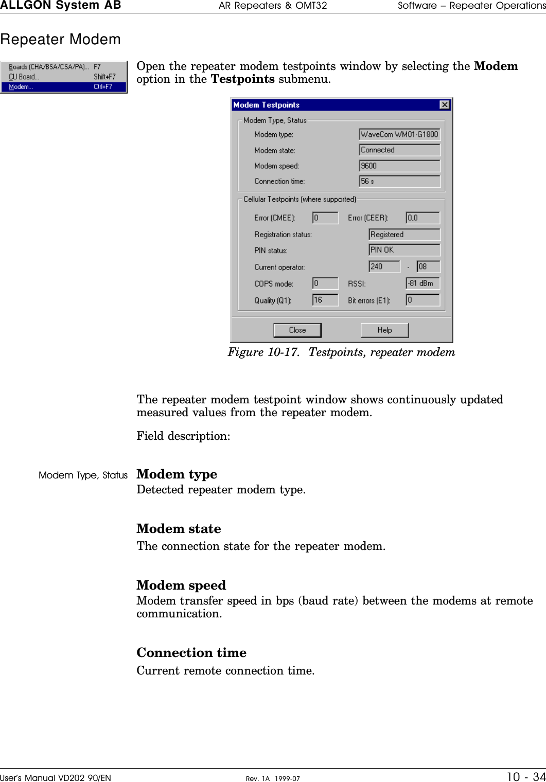
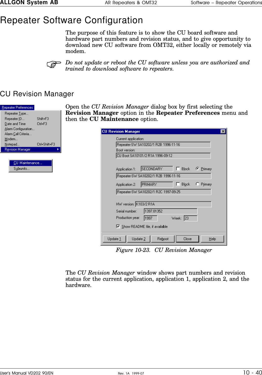
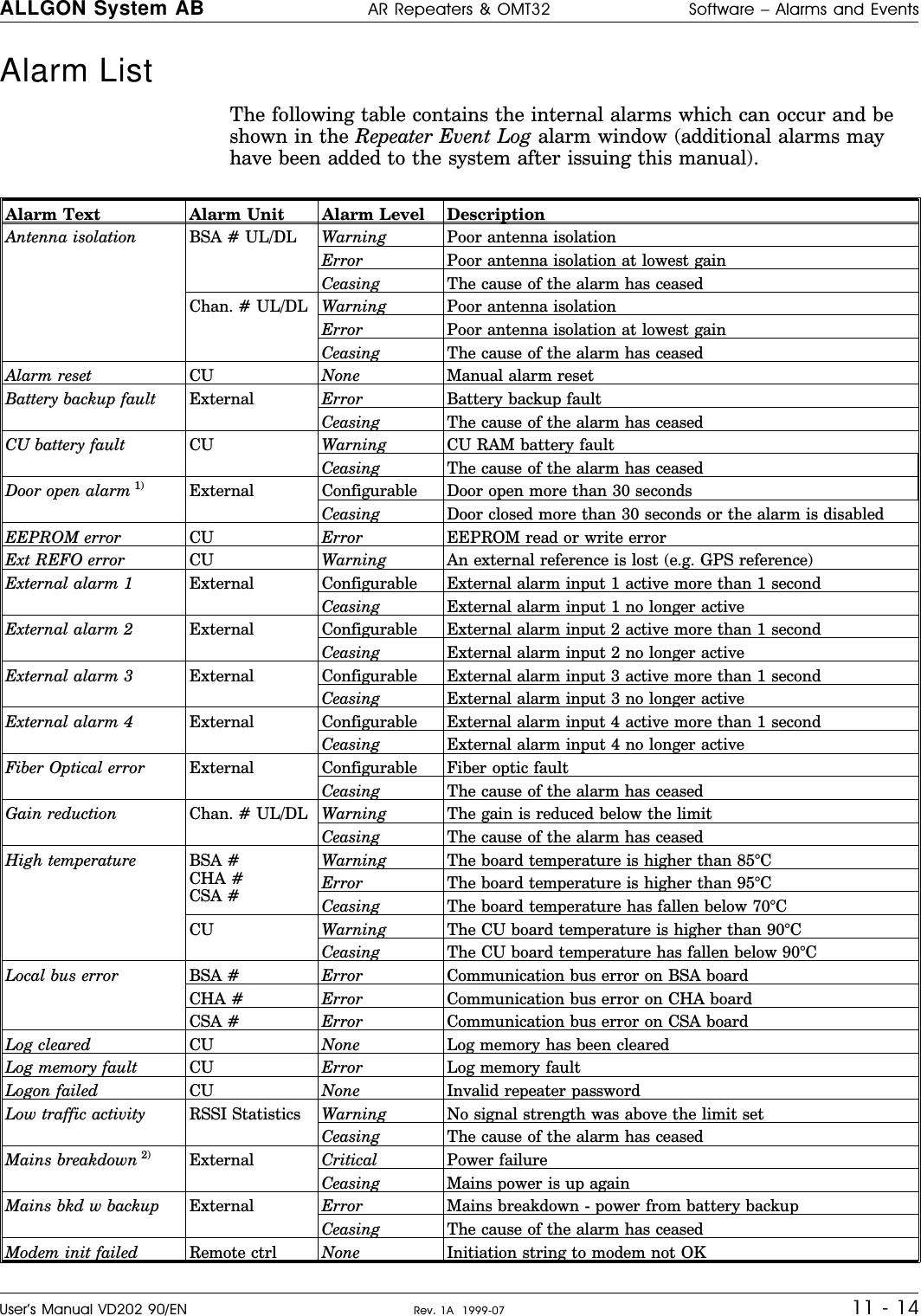
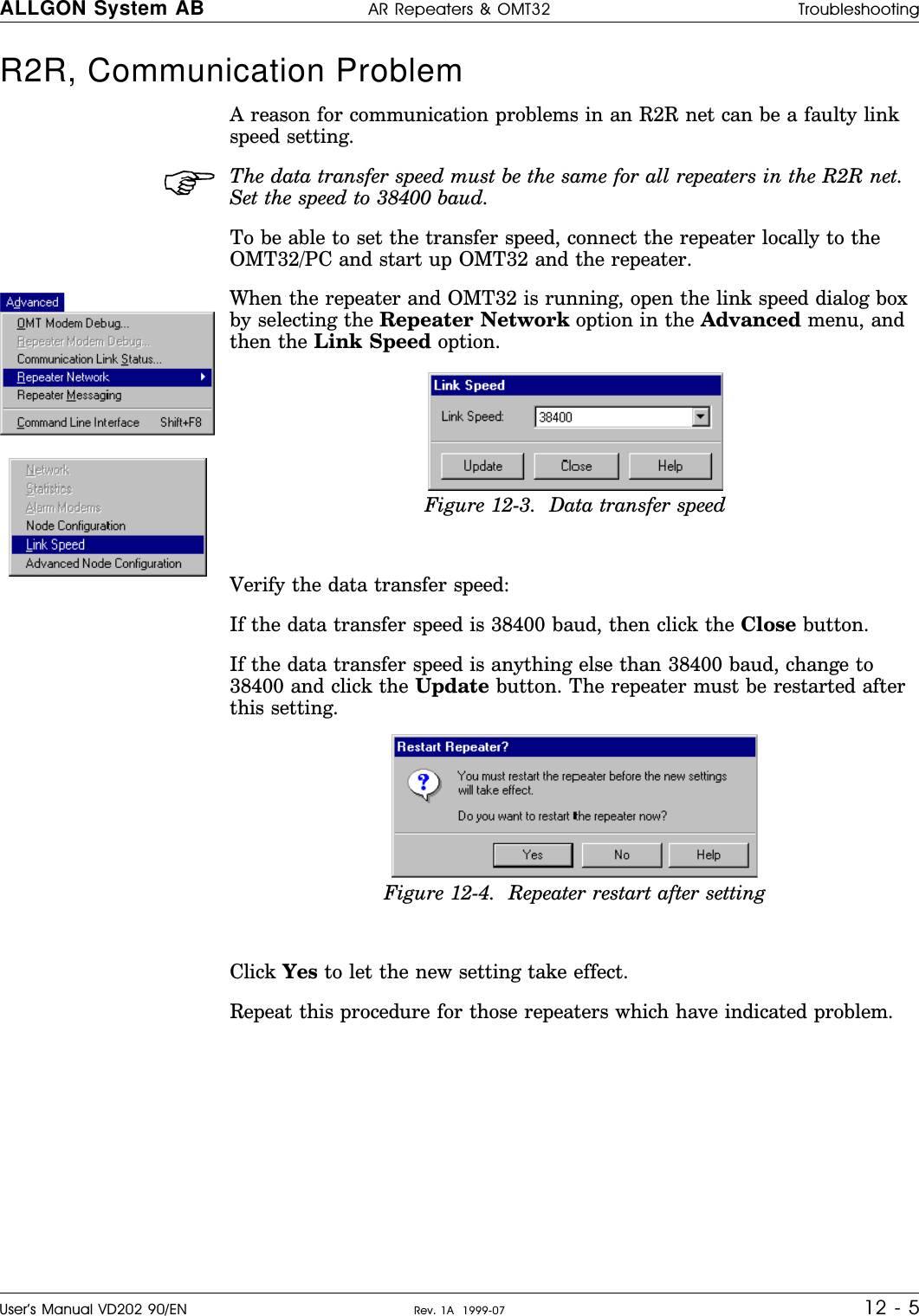
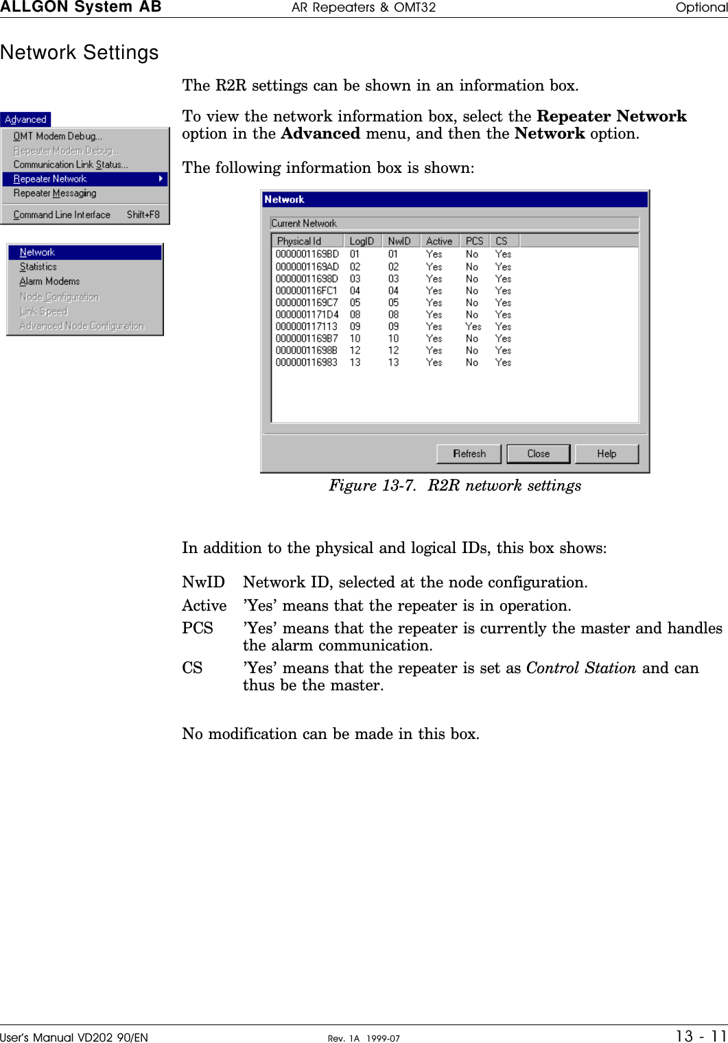
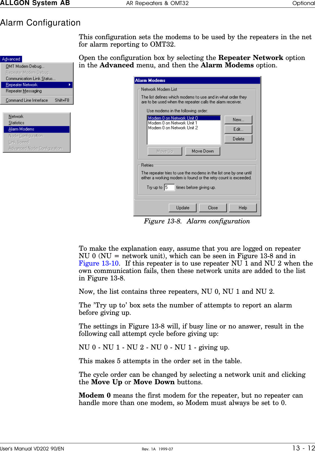
![Command Line Interface The Command Line Interface, CLI, is provided as a quick way ofcommunicating with a connected repeater. Rather than using the normalWindows dialog boxes the user can interact with the repeater moredirectly.The Command Line Interface feature does not check whether enteredvalues are within permitted range or not. So, you MUST know the systemvery well before setting gain and power levels using the Command LineInterface.The CLI provides several advantages:•Users accustomed to a keyboard based operating system do not have toadjust immediately to an entirely novel system.•Single parameters can be set.•Without touching the mouse, the experienced user can performoperations quicker.•Using the CLI prevents the screen from getting clogged up with lots ofwindows.•Using the CLI is more memory efficient.If the CLI is iconized, then double-click the Command Line Interface iconor select the Command Line Interface option in the Advanced menu.Commands can be entered on the command line like this:By clicking the last entered commands can be reselected, edited andentered again.A command list with command syntax is found below.Command SyntaxThe following command syntax is valid for the Command Line Interface:MAIN_COMMAND-SUB_COMMAND [:PAR1, PAR2, ...];Note that each line must be ended with a semicolon (;).If a command is entered with an incorrect syntax, an error message witha mismatch explanation is shown.ALLGON System AB AR Repeaters & OMT32 Software – OMT32 FeaturesUser’s Manual VD202 90/EN Rev. 1A 1999-07 9 - 6](https://usermanual.wiki/Powerwave-Technologies/AR3530.users-manual/User-Guide-116307-Page-102.png)
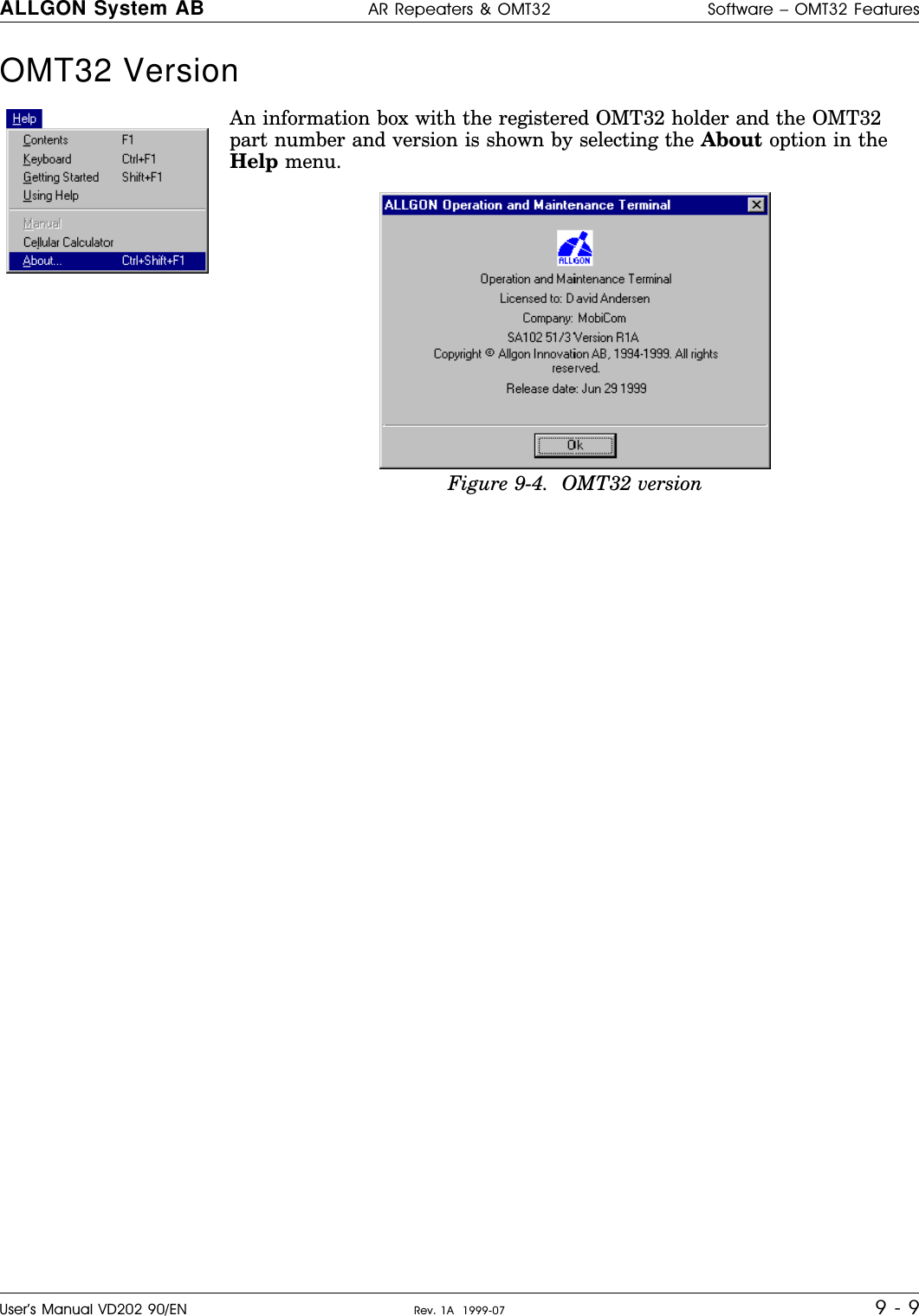
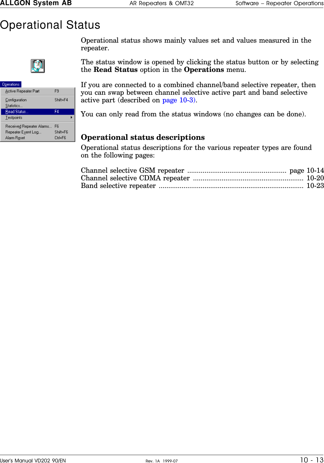
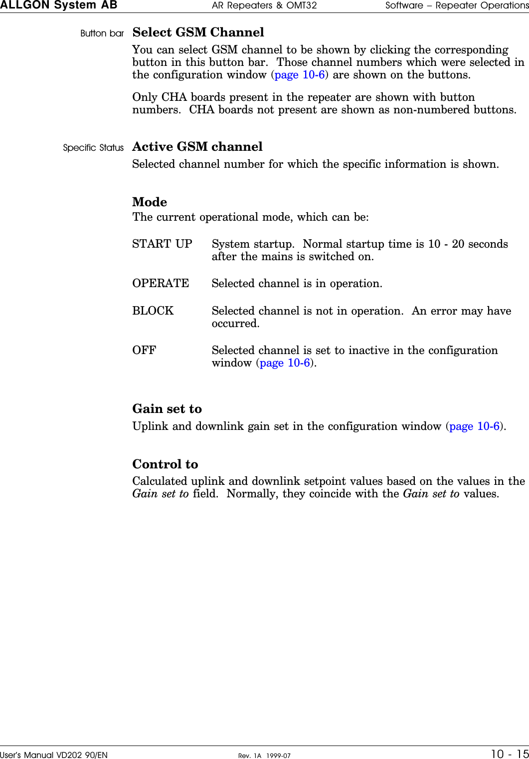
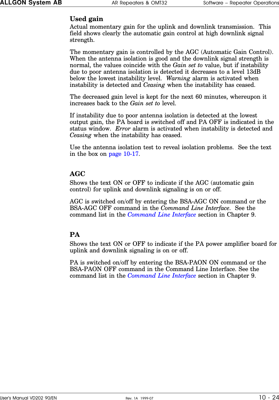
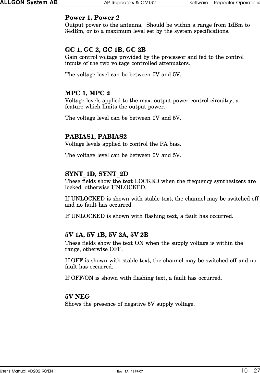
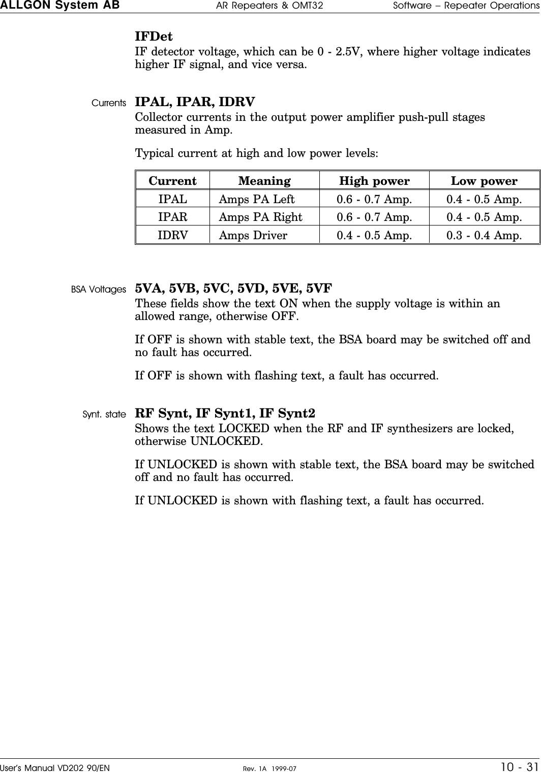
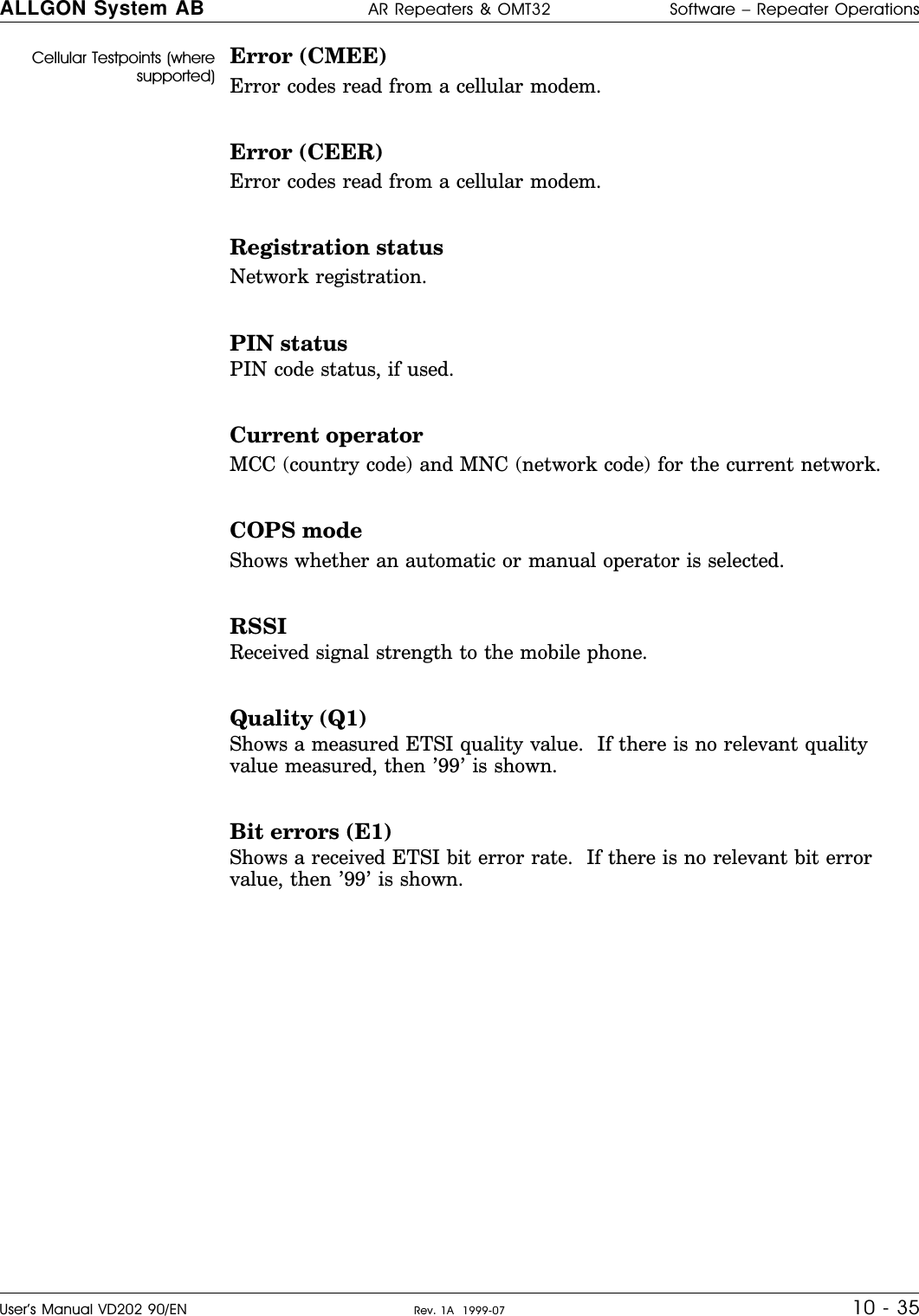
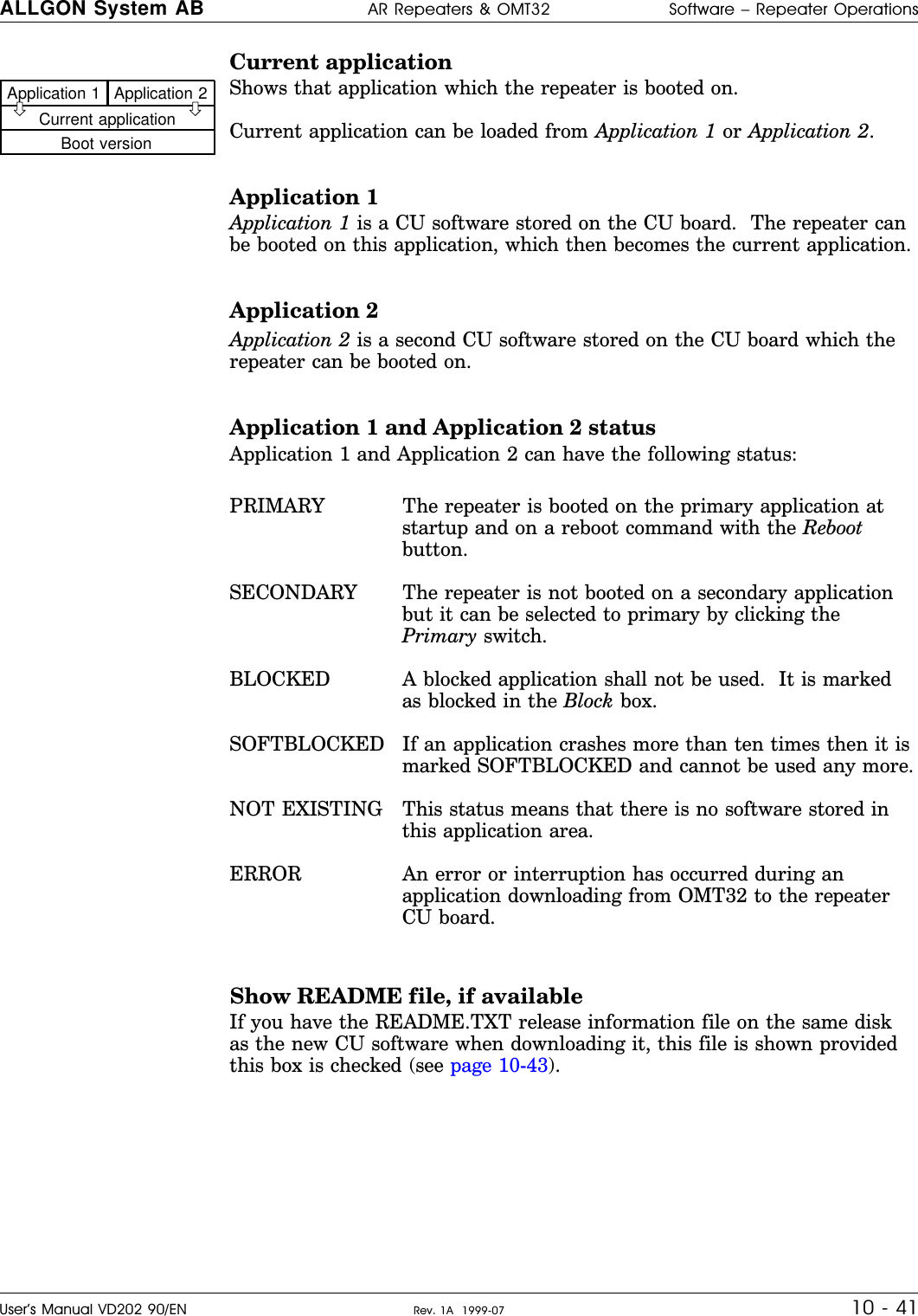
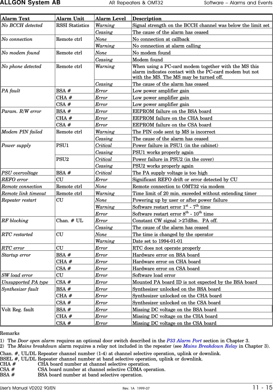
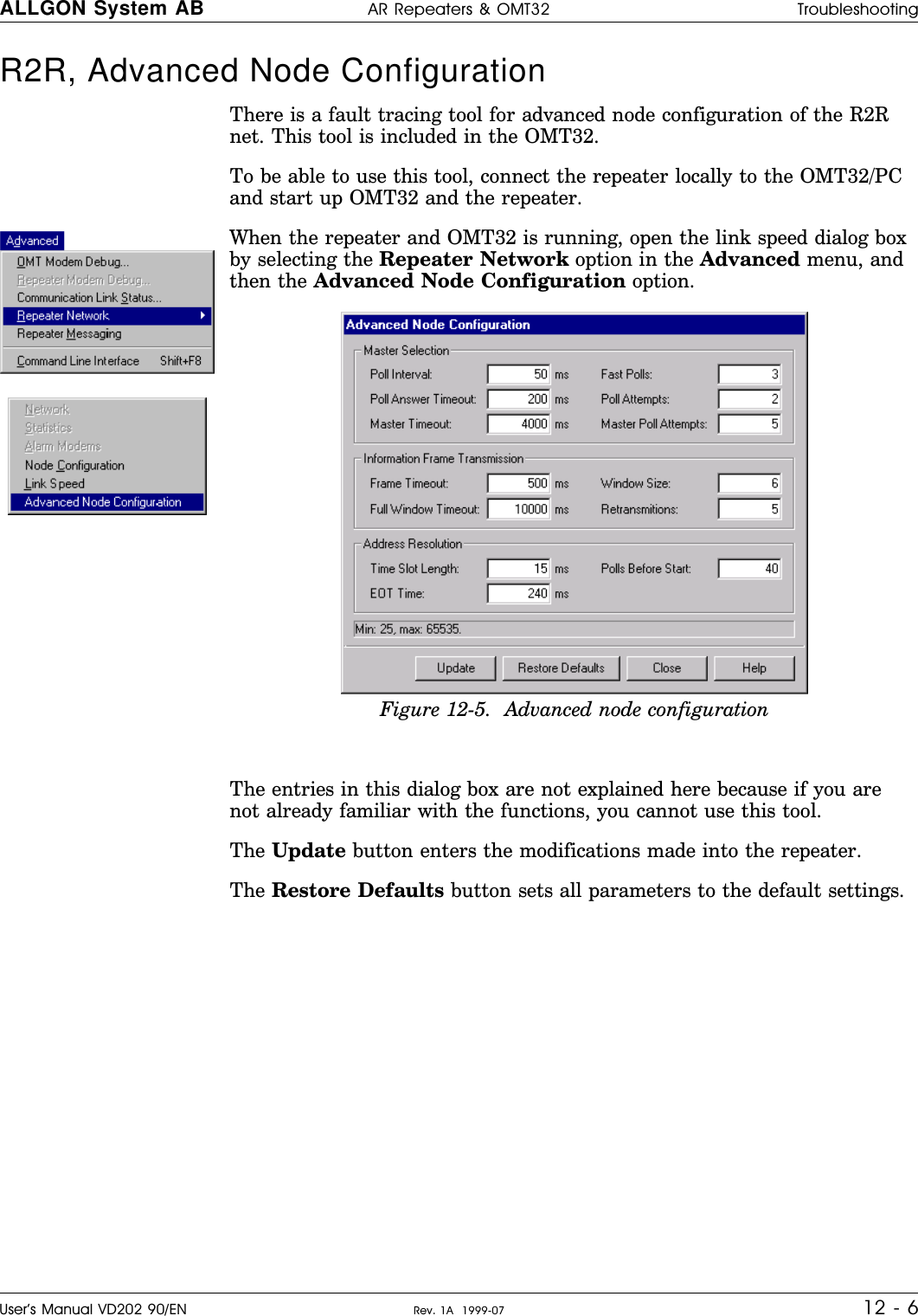
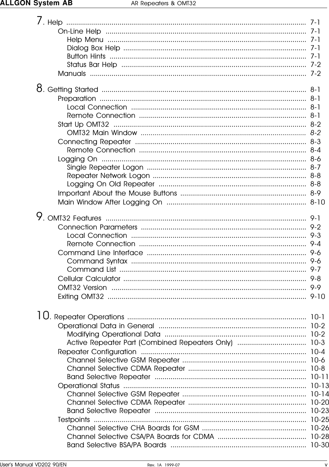
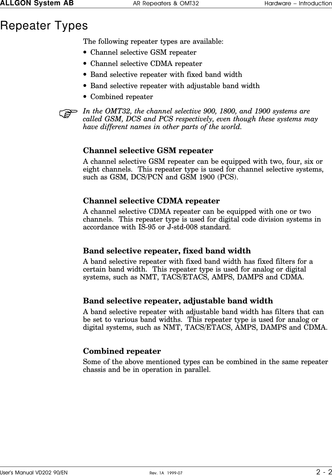
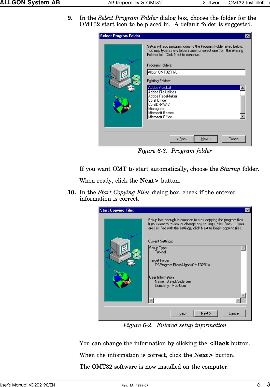
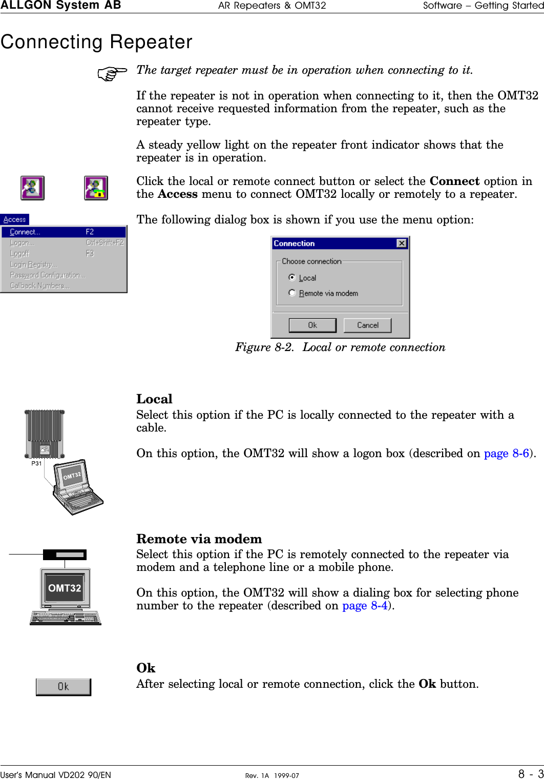
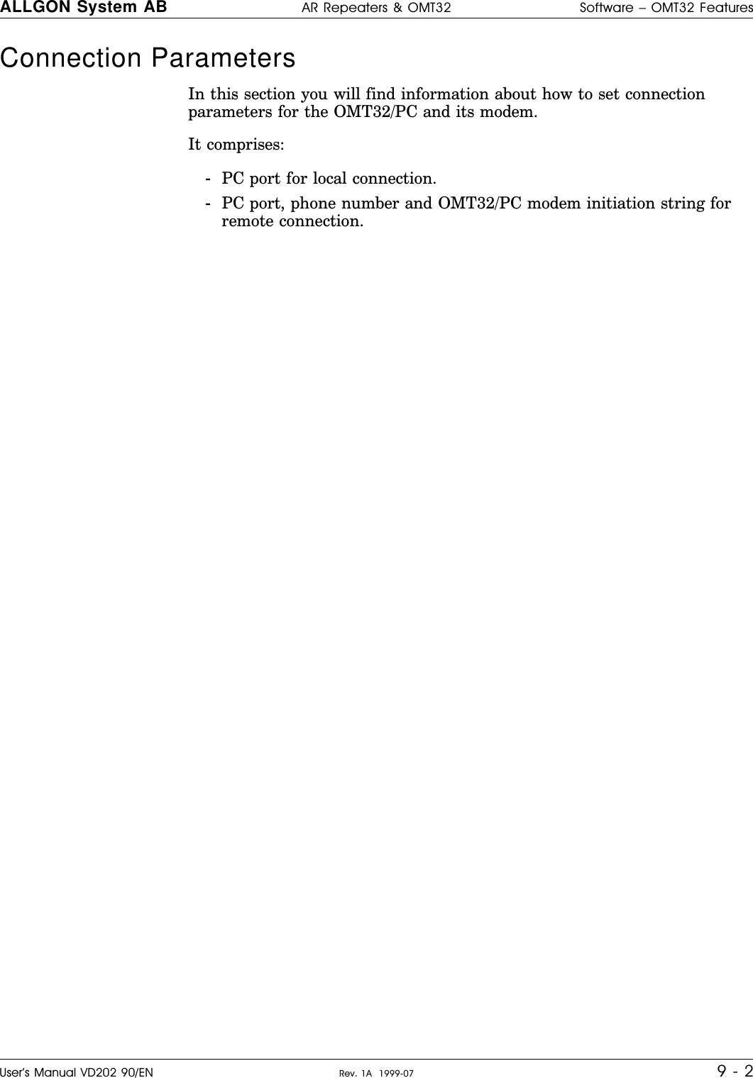
![Command ListMain Command Command/Parameter/Sample DescriptionOM OM-EXIT Exits the OMT32 programGeneral OMT32 program Parameter: [NOW] No confirmationEx.: OM-EXIT; Exit after confirmationEx.: OM-EXIT: NOW; Exit without confirmationTIME TIME-WRT Time settingInternal repeater clock date andtimeParameter: HH.MM.SS Hour-Minute-SecondEx.: TIME-WRT: 13.25.30; Time setting: 13:25:30TIME-WRD Date settingParameter: YYYY-MM-DD-WW[W...] Year-Month-Day-WeekdayEx.: TIME-WRD: 1999-07-12-MON; Date setting 1999-07-12-MondayPAR PAR-COMBATT Uplink/downlink combiner attenuationParameters and repeater ID Parameter 1: U[P]/D[OWN Uplink/DownlinkParameter 2: value Combiner attenuation valueEx.: PAR-COMBATT: U, 6; Uplink combiner attenuation 6dBmPAR-CHAN Links a repeater channel to a GSM/CDMAchannelParameter 1: # Repeater channel number (1-4)Parameter 2: # GSM/CDMA channel numberEx.: PAR-CHAN: 2, 116; Repeater channel #2 is linked toGSM/CDMA channel #116PAR-CHACT Turns a repeater channel on/offParameter 1: # Repeater channel number (1-4)Parameter 2: ON/OFF Channel on/offEx.: PAR-CHACT: 3, ON; Repeater channel #3 onPAR-GAIN Uplink or downlink channel gainParameter 1: # Repeater channel number (1-4)Parameter 2: U[P]/D[OWN Uplink/DownlinkParameter 3: value Gain valueEx.: PAR-GAIN: 4, D, 34; Repeater channel #4 downlink 34dB gainPAR-REPID Connected repeater is assigned a new IDstringParameter: string ID for the connected repeaterEx.: PAR-REPID: new; Connected repeater ID = ’new’BSA BSA-GAIN Uplink or downlink gainBand selective parameter Parameter 1: U[P]/D[OWN Uplink/DownlinkParameter 2: value Gain valueEx.: BSA-GAIN: DOWN, 36; Downlink gain 36dBBSA-FREQ Uplink or downlink frequencyParameter 1: U[P]/D[OWN] Uplink/DownlinkParameter 2: value (12.5KHz steps) Frequency in MHzEx.: BSA-FREQ: UP, 890.5; Uplink frequency 890.5 MHzBSA-AGC Uplink or downlink Automatic GainControl on/offParameter 1: U[P]/D[OWN] Uplink/DownlinkParameter 2: ON/OFF Automatic gain control on/offEx.: BSA-AGC: D, ON; Downlink AGC onBSA-PAON Uplink or downlink PA board on/offParameter 1: U[P]D[OWN Uplink/DownlinkParameter 2: ON/OFF PA board on/offEx.: BSA-PAON: UP, OFF; Uplink PA offALLGON System AB AR Repeaters & OMT32 Software – OMT32 FeaturesUser’s Manual VD202 90/EN Rev. 1A 1999-07 9 - 7](https://usermanual.wiki/Powerwave-Technologies/AR3530.users-manual/User-Guide-116307-Page-103.png)