Powerwave Technologies AR3530 PCS Channel Selective Repeater User Manual AR Repeaters User s Manual
Powerwave Technologies Inc. PCS Channel Selective Repeater AR Repeaters User s Manual
Contents
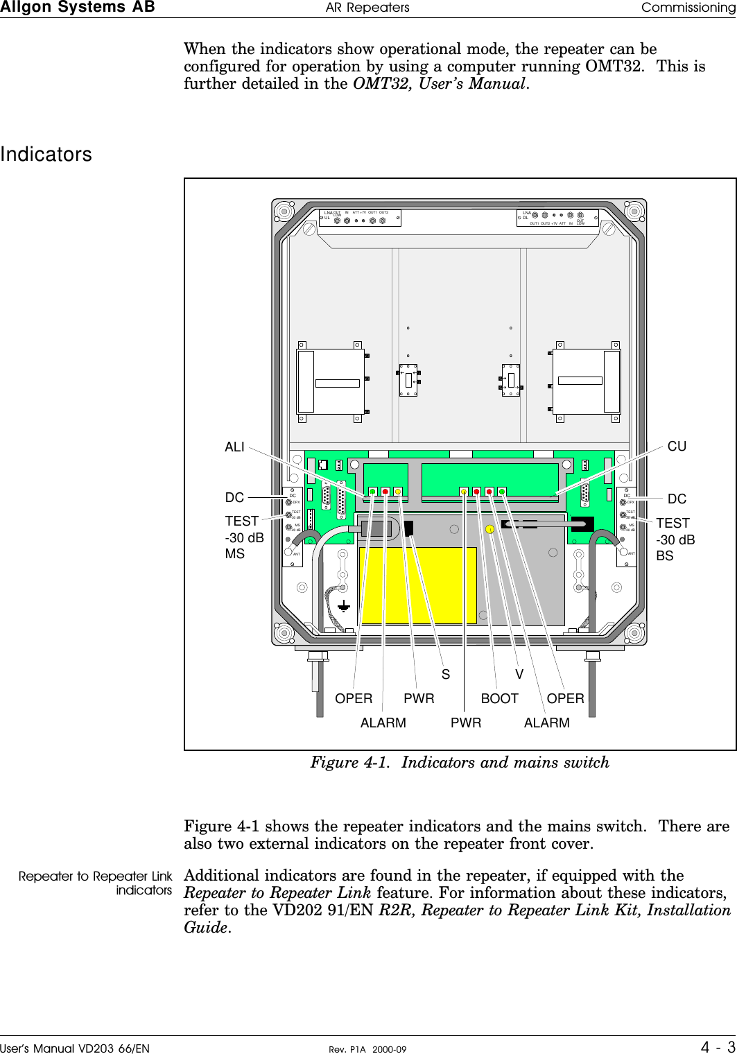
- 1. users manual
- 2. New notated manual per request
- 3. original manual
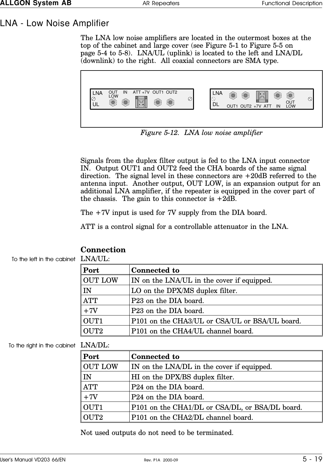
original manual