Powerwave Technologies AR3530 PCS Channel Selective Repeater User Manual AR Repeaters User s Manual
Powerwave Technologies Inc. PCS Channel Selective Repeater AR Repeaters User s Manual
Contents
- 1. users manual
- 2. New notated manual per request
- 3. original manual
original manual
User’s Manual
AR Repeaters
VD203 66/EN - English Future on Demand.

User’s Manual
AR Repeaters
Channel Selective and Band Selective Repeaters
–
English
Allgon Systems AB AR Repeaters
VD203 66/EN - User’s Manual Rev. P1A 2000-09 i

This document describes installation, commissioning and the design of the Allgon AR Repeaters.
Communication between Allgon AR repeaters and operators is carried out either by using Allgon OMT32 (Operation and
Maintenance Terminal), or Allgon OMS (Operation and Maintenance System). OMT32 is described in the OMT32, User’s
Manual. OMS is described in the Advanced Repeater OMS, User’s Manual.
Hardware and software mentioned in this document are subjected to continuous development and improvement.
Consequently, there may be minor discrepancies between the information in the document and the performance and
design of the product. Specifications, dimensions and other statements mentioned in this document are subject to change
without notice.
Allgon and its suppliers shall not be liable for any damages related to the software or hardware, or for any other damages whatsoever caused of the use of or
inability to use any Allgon product. This is applicable even if Allgon has been advised of the damage risk. Under any circumstances, Allgon’s entire liability
shall be limited to replace such defective software or hardware which was originally purchased from Allgon.
Teflon is a registered trademark of Du Pont. Other trademarks mentioned in this document are trademarks or registered trademarks of their respective
owners.
This document is produced by El, Tele & Maskin Ingenjörsfirma AB, Huddinge, Sweden.
Printed in Sweden.
Allgon Systems AB, SE-187 80 Täby, Sweden
Phone: +46 8 540 822 00 – Fax: +46 8 540 834 80 – Internet: www.allgon.com
This document or parts of it may not be reproduced without the written permission of Allgon Systems AB.
Infringements will be prosecuted. All rights reserved.
Copyright © Allgon Systems AB, Sweden, 1994-2000.
AR Repeaters Allgon Systems AB
ii Rev. P1A 2000-09 VD203 66/EN - User’s Manual

Contents
Abbreviations ............................................................................................................... vi
1. Safety ....................................................................................................................... 1-1
Warning Signs ..................................................................................................... 1-2
Static Electricity .................................................................................................. 1-2
2. Introduction ............................................................................................................. 2-1
Repeater Types .................................................................................................. 2-2
Using Repeaters ................................................................................................. 2-3
Shaded Area ................................................................................................. 2-4
Sports Arena ................................................................................................... 2-5
3. Installation ................................................................................................................ 3-1
Siting the Repeater ............................................................................................ 3-1
Sunshine ......................................................................................................... 3-1
Shelter ............................................................................................................. 3-1
Outdoor Installation and Service Limitations .............................................. 3-1
Dimensions and Weights ................................................................................... 3-2
Mounting ............................................................................................................. 3-4
Connection ........................................................................................................ 3-7
Connection Ports and Station Ground ............................................................ 3-10
Station Ground .............................................................................................. 3-10
P27 Auxiliary Port ........................................................................................... 3-11
P31 PC Port .................................................................................................... 3-11
P32 Modem Port ........................................................................................... 3-12
P33 Alarm Port ............................................................................................... 3-12
P34 Repeater to Repeater Link Port ............................................................ 3-14
Mains Breakdown Relay .................................................................................... 3-15
Installing 24 Volt or 48 Volt DC Power Supply Unit ......................................... 3-16
4. Commissioning ........................................................................................................ 4-1
Starting the Repeater ........................................................................................ 4-2
Indicators ....................................................................................................... 4-3
Measuring the Output Power Level .................................................................. 4-4
Voltage Supply Testpoints ................................................................................. 4-4
Repeater Configuration .................................................................................... 4-4
5. Functional Description ............................................................................................ 5-1
Repeater Design ................................................................................................ 5-2
Channel Selective GSM Repeater ............................................................... 5-4
Channel Selective CDMA Repeater ............................................................ 5-5
Channel Selective High Power CDMA Repeater ........................................ 5-6
Band Selective Repeater ............................................................................. 5-7
Combined Repeater .................................................................................... 5-8
Allgon Systems AB AR Repeaters
VD203 66/EN - User’s Manual Rev. P1A 2000-09 iii

Block Diagram .................................................................................................... 5-9
Downlink Signal Path ..................................................................................... 5-9
Uplink Signal Path .......................................................................................... 5-9
Channel Selective GSM Repeater ............................................................... 5-10
Channel Selective CDMA Repeater ............................................................ 5-12
Band Selective Repeater ............................................................................. 5-14
RCU ................................................................................................................. 5-15
R2R ................................................................................................................. 5-15
Alarm .............................................................................................................. 5-16
Repeater Setup ............................................................................................. 5-16
Board and Unit Descriptions ............................................................................. 5-17
DC - Directional Coupler .............................................................................. 5-17
DPX - Duplex Filter ......................................................................................... 5-18
LNA - Low Noise Amplifier ............................................................................. 5-19
CHA - Channel Amplifier Board for Channel Selective Operation .......... 5-20
CSA and PA Boards for Channel Selective CDMA Operation .................. 5-21
BSA and PA Boards for Band Selective Operation ..................................... 5-22
DIA Board ....................................................................................................... 5-23
CU Control Unit Board ................................................................................... 5-25
Repeater CU Software and Hardware Compatibility ................................. 5-26
Cabling ............................................................................................................... 5-27
Channel Selective GSM Repeater, 2 Channels ......................................... 5-28
Channel Selective GSM Repeater, 4 Channels ......................................... 5-29
Channel Selective CDMA Repeater ............................................................ 5-30
Channel Selective High Power CDMA Repeater ........................................ 5-31
Band Selective Repeater ............................................................................. 5-32
6. Optionals .................................................................................................................. 6-1
RCU, Remote Control Unit for GSM 900 .......................................................... 6-2
RCU, Remote Control Unit with PCMCIA Modem ........................................... 6-4
OMS, Operation and Maintenance System .................................................... 6-8
Traffic Statistics ................................................................................................... 6-8
Battery Backup ................................................................................................... 6-8
Fiber Optic Interface ......................................................................................... 6-8
7/16" Antenna Cable Connectors ................................................................... 6-8
R2R, Repeater To Repeater Link ....................................................................... 6-9
Requirements ................................................................................................. 6-9
Installation ...................................................................................................... 6-10
Configuration ................................................................................................. 6-10
7. Repeater Alarms ..................................................................................................... 7-1
Alarm Reference List ......................................................................................... 7-2
Index .............................................................................................................................. I-1
Questionnaire .............................................................................................................. Q-1
AR Repeaters Allgon Systems AB
iv Rev. P1A 2000-09 VD203 66/EN - User’s Manual

Figures
Figure 2-1. Allgon AR Repeater ................................................................................. 2-1
Figure 2-2. Repeater coverage of shaded area ..................................................... 2-4
Figure 2-3. Repeater in sports arena ........................................................................ 2-5
Figure 3-1. Repeater dimensions ............................................................................... 3-2
Figure 3-2. High power CDMA repeater ................................................................... 3-2
Figure 3-3. Attaching the bracket to a wall ............................................................. 3-4
Figure 3-4. Attaching the bracket to a pole ............................................................ 3-5
Figure 3-5. Attaching the bracket to a mast ........................................................... 3-5
Figure 3-6. Attaching the repeater to the bracket .................................................. 3-6
Figure 3-7. MS and BS antenna connections ........................................................... 3-7
Figure 3-8. Connection ports and station ground ................................................... 3-10
Figure 3-9. Mains breakdown relay connection ...................................................... 3-15
Figure 3-10. Replacing the PSU ................................................................................. 3-16
Figure 4-1. Indicators and mains switch ................................................................... 4-3
Figure 5-1. Channel selective GSM repeater ........................................................... 5-4
Figure 5-2. Channel selective CDMA repeater ........................................................ 5-5
Figure 5-3. High power CDMA repeater ................................................................... 5-6
Figure 5-4. Band selective repeater .......................................................................... 5-7
Figure 5-5. Combined repeater ................................................................................ 5-8
Figure 5-6. Block diagram, channel selective repeater ......................................... 5-10
Figure 5-7. Block diagram, CDMA repeater ............................................................. 5-12
Figure 5-8. Block diagram, band selective repeater .............................................. 5-14
Figure 5-9. MS and BS directional coupler ............................................................... 5-17
Figure 5-10. BS directional coupler, high power CDMA .......................................... 5-17
Figure 5-11. MS directional coupler, high power CDMA ......................................... 5-17
Figure 5-12. LNA low noise amplifier ......................................................................... 5-19
Figure 5-13. DIA board connectors and testpoints ................................................. 5-23
Figure 5-14. Cabling, GSM repeater - 2 ch. ............................................................ 5-28
Figure 5-15. Cabling, GSM repeater - 4 ch. ............................................................ 5-29
Figure 5-16. Cabling, CDMA repeater - 2 ch. ......................................................... 5-30
Figure 5-17. Cabling, high power CDMA repeater - 2 ch. ..................................... 5-31
Figure 5-18. Cabling, band selective repeater ....................................................... 5-32
Figure 6-1. RCU - GSM 900 type ............................................................................... 6-2
Figure 6-2. RCU - Fixed Wire Line PCMCIA type ....................................................... 6-5
Figure 6-3. RCU - Wireless PCMCIA type ................................................................... 6-6
Figure 6-4. Repeater to Repeater Link ...................................................................... 6-9
Allgon Systems AB AR Repeaters
VD203 66/EN - User’s Manual Rev. P1A 2000-09 v

Abbreviations
Abbreviations used in this manual, in the software, and in the repeater:
AGC Automatic Gain Control
ALI Alarm Interface board
AMPS Advanced Mobile Phone Service
BCCH Broadcast Control Channel (GSM broadcast channel time slot)
BS Base Station, BS antenna = towards the base station
BSA Band Selective Amplifier board for uplink or downlink band with fixed or
adjustable band width
BSel Band Selective
CDMA Code Division Multiple Access
CHA Channel Amplifier board with 2 channel selective uplink or downlink channels
CMB Combiner unit
CSA CDMA Segment Amplifier board with 2 channel selective uplink or downlink
channels
CSel Channel Selective
CU Control Unit board
CW Continuous Wave
DAMPS Digital Advanced Mobile Phone Service
DC Directional Coupler
DCS Digital Communication System (same as PCN)
DIA Distribution board
DL Downlink signal direction (from base station via repeater to mobile station)
DPX Duplex filter
EEPROM Electrical Erasable Programmable Read Only Memory
EGSM Extended Global System for Mobile communication
ETACS Extended Total Access Communication System
ETSI European Telecommunications Standard Institute
GSM Global System for Mobile communication
HW Hardware
LED Light Emitting Diode
LNA Low Noise Amplifier, uplink and downlink
MS Mobile Station, MS antenna = towards the mobile station
MSC Mobile Switching Center
NMT Nordic Mobile Telephone system
OMS Operation and Maintenance System
OMS/PC Desktop or notebook with installed OMS software
OMT32 Operation and Maintenance Terminal
OMT32/PC Desktop or notebook with installed OMT32 software
PA Power Amplifier board for uplink or downlink
PCN Personal Communication Network (same as DCS)
PCS Personal Communication System
PSU Power Supply Unit
PTFE Polytetrafluoro Ethylene (Teflon)
RCU Remote Control Unit
RF Radio Frequency
RIA Repeater to Repeater Interface Adapter
RSSI Received Signal Strength Indication
RTC Real Time Clock
SW Software
TACS Total Access Communication System
TDMA Time Division Multiple Access
UL Uplink signal direction (from mobile station via repeater to base station)
UPS Uninterruptible Power Supply
AR Repeaters Allgon Systems AB
vi Rev. P1A 2000-09 VD203 66/EN - User’s Manual
1. Safety
Any personnel involved in installation, operation or service of Allgon
repeaters must understand and obey the following:
•Allgon repeaters are designed to receive and amplify signals from one or
more base stations and retransmit the signals to one or more mobile
stations. Also, the repeaters are designed to receive signals from one or
more mobile stations, amplify and retransmit to the base stations. The
repeaters must be used exclusively for these purposes and nothing else.
•Repeaters supplied from the mains must be connected to grounded
outlets and in conformity with any local regulations.
•The power supply unit in repeaters supplied from the mains contains
dangerous voltage that can cause electric shock. Disconnect the mains
prior to any work in such a repeater. Any local regulations are to be
followed when servicing repeaters.
Authorized service personnel only are allowed to service repeaters while
the mains is connected.
•The repeater cover must be secured in opened position, e.g. by tying it
up, at outdoor repeater work. Otherwise, the cover can be closed by the
wind and cause your fingers getting pinched or your head being hit.
•When working on a repeater on high ground, e.g. on a mast or pole, be
careful not to drop parts or the entire repeater. Falling parts can cause
serious personal injury.
•Any repeater, including this repeater, will generate radio signals and
thereby give rise to electromagnetic fields that may be hazardous to the
health of any person who is extensively exposed to the signals at the
immediate proximity of the repeater and the repeater antennas.
BERYLLIUM OXIDE
•The CHA channel board power transistors, the PA amplifier board
power transistors, and the combiners (CMB) contain beryllium oxide
(BeO) that is poisonous if present as dust or smoke which can be
inhaled. The power transistors mentioned are mounted with two
screws as opposed to other transistors.
Do not file, grind, machine, or treat these parts with acid.
Warning signs are applied on boards and units that contain beryllium
oxide. These warning signs are shown in the next section.
HYDROGEN FLUORIDE
•The coaxial cable insulation is made of PTFE, polytetrafluoro ethylene,
that gives off small amounts of hydrogen fluoride when heated.
Hydrogen fluoride is poisonous. Do not use heating tools when
stripping off coaxial cable insulation.
No particular measures are to be taken in case of fire because the
emitted concentration of hydrogen fluoride is very low.
Allgon Systems AB AR Repeaters Safety
VD203 66/EN - User’s Manual Rev. P1A 2000-09 1 - 1
•A lithium battery is permanently mounted on the CU board. Due to
the risk of explosion, this battery must not be removed from the board.
In case of battery malfunction, replace the CU board. The old CU
board can be sent to Allgon for repair.
•The heat sink element on the CDMA High Power repeater can be very
hot. Do not touch this surface during operation.
Warning Signs
The following warning signs must be observed and be kept clean and
readable.
Beryllium oxide
This warning sign is applied on boards and units which contain beryllium
oxide parts.
This warning sign is applied at the bottom, inside the cabinet, below the
power supply unit.
The previous section details parts containing beryllium oxide and how to
avoid dangerous dealing with these parts.
Static Electricity
Static electricity means no risk of personal injury but it can severely
damage essential parts of the repeater, if not handled carefully.
Parts on the printed circuit boards as well as other parts in the repeater
are sensitive to electrostatic discharge.
Never touch the printed circuit boards or uninsulated conductor
surfaces unless absolutely necessary.
If you must handle the printed circuit boards or uninsulated conductor
surfaces, use ESD protective equipment, or first touch the repeater
chassis with your hand and then do not move your feet on the floor.
Never let your clothes touch printed circuit boards or uninsulated
conductor surfaces.
Always store printed circuit boards in ESD-safe bags.
Beryllium
oxide
hazard
BERYLLIUM OXIDE
(Toxic)
used in equipment
see instruction book
Safety AR Repeaters Allgon Systems AB
1 - 2 Rev. P1A 2000-09 VD203 66/EN - User’s Manual
2. Introduction
Allgon repeaters are used to fill out uncovered areas in cellular mobile
systems, such as base station fringe areas, road tunnels, business and
industrial buildings, etc.
A repeater receives signals from a base station, amplifies and retransmits
the signals to mobile stations. Also it receives, amplifies and retransmits
signals in the opposite direction. Both directions are served
simultaneously.
To be able to receive and transmit signals in both directions, the repeater
is connected to a donor antenna directed towards the base station and to
a service antenna directed towards the area to be covered.
Control of the repeaters is performed using a desktop or notebook loaded
with the Allgon OMT32, Operation and Maintenance Terminal, which can
communicate with the repeaters, either locally or remotely via modem.
Remote operation can be performed either via a traditional telephone line
or via a mobile phone that can be installed inside the repeater.
To be able to control many Allgon AR repeaters in common, there is an
Allgon OMS, Operation and Maintenance System.
The repeaters and the OMT32 is described in this manual. The OMS is
described in the OMT32, User’s Manual.
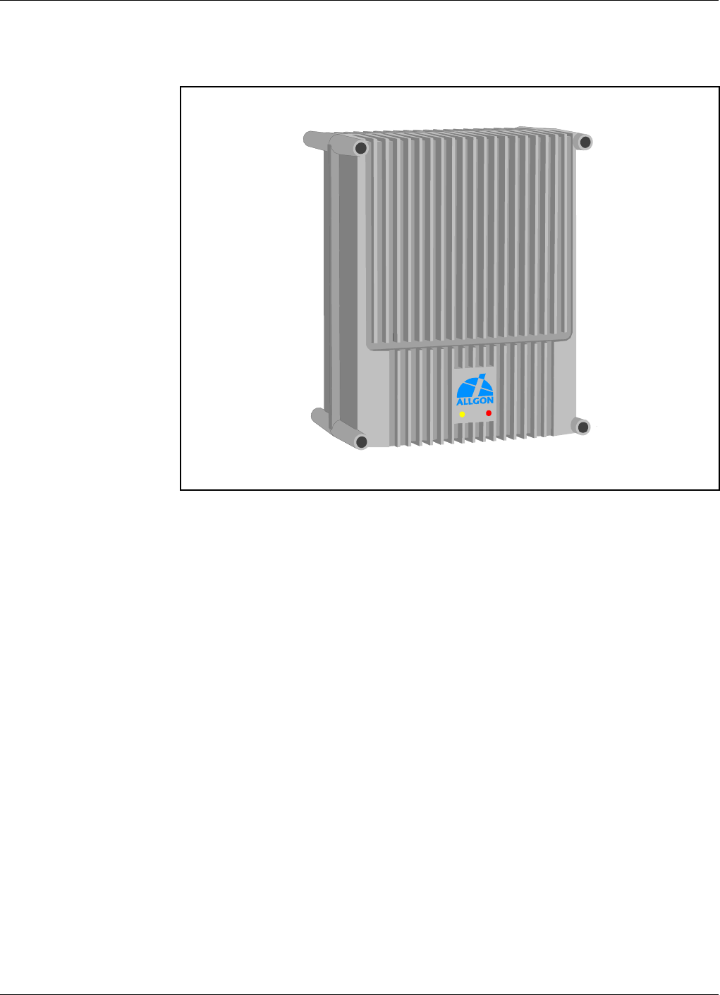
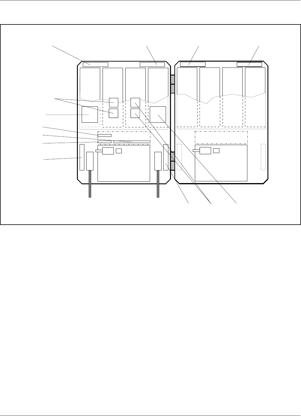
Figure 2-1. Allgon AR Repeater
Allgon Systems AB AR Repeaters Introduction
User’s Manual VD203 66/EN Rev. P1A 2000-09 2 - 1

Repeater Types
The following repeater types are currently available:
•Channel selective GSM repeater
•Channel selective CDMA repeater
•Channel selective high power CDMA repeater
•Band selective repeater with fixed bandwidth
•Band selective repeater with adjustable bandwidth
•Combined repeater
In the OMT32, the channel selective 900, 1800, and 1900 systems are
called GSM, DCS and PCS respectively, even though these systems may
have different names in other parts of the world.
Channel selective GSM repeater
A channel selective GSM repeater can be equipped with two, four, six or
eight channels. This repeater type is used for channel selective systems,
such as GSM, DCS, PCN and GSM 1900 (PCS).
Channel selective CDMA repeater
A channel selective CDMA repeater can be equipped with one or two
channels. This repeater type is used for digital code division systems in
accordance with IS-95 or J-std-008 standard.
Channel selective high power CDMA repeater
A channel selective CDMA repeater like the previous one, but equipped
with a 6dB (typically) BA (Booster Amplifier) unit.
Band selective repeater with fixed bandwidth
A band selective repeater with fixed bandwidth has fixed filters for a
certain bandwidth. This repeater type is used for analog or digital
systems, such as NMT, GSM, TACS, ETACS, AMPS, DAMPS and CDMA.
Band selective repeater with adjustable bandwidth
A band selective repeater with adjustable bandwidth has filters that can
be set to various bandwidths. This repeater type is used for analog or
digital systems, such as NMT, TACS, ETACS, AMPS, DAMPS and CDMA.
Combined repeater
Some of the above mentioned types can be combined in the same repeater
chassis and be in operation in parallel.
Introduction AR Repeaters Allgon Systems AB
2 - 2 Rev. P1A 2000-09 User’s Manual VD203 66/EN

Using Repeaters
In areas where the radio signal propagation is poor repeaters can be used
to fill out those areas which are not covered by the base station.
The following scenarios are examples on this:
–Sports arenas
–Fair halls
–Large shopping centres
–Road and railway tunnels
–Indoors in buildings with metal or concrete walls
Other examples where repeaters can be used to increase the coverage are:
–Shaded areas
–Fringe coverage areas
In areas where the traffic intensity is low, it is not cost efficient to install
a base station. An Allgon repeater, which can be installed with a
minimum of investments, is a much better solution. You save installation
costs as well as operational costs.
Examples of using repeaters
Two examples are described in the following sections. An outdoor example
in a shaded valley and an indoor example in a sports arena.
Allgon Systems AB AR Repeaters Introduction
User’s Manual VD203 66/EN Rev. P1A 2000-09 2 - 3
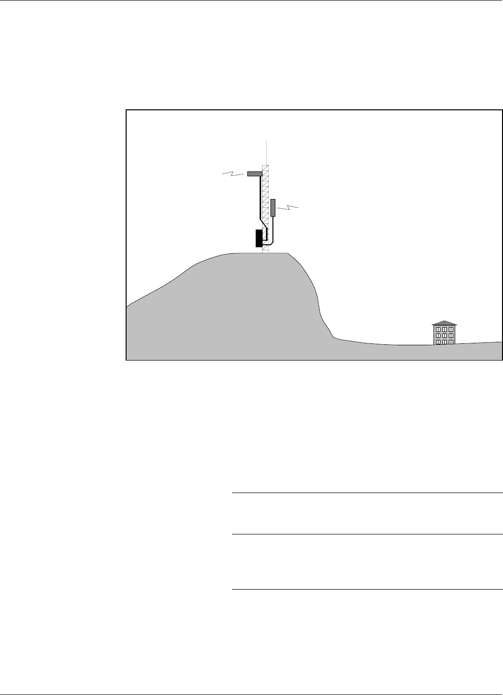
Shaded Area
A valley is shaded by hills. There is a base station 5 kilometers away, but
the lowest signal strength in the valley is less than –100dBm. A mast
used for other purposes is available for a repeater installation. The mast
height is 42 meter and it is located on a hill. The scenario is illustrated
in Figure 2-2.
The donor antenna of the repeater was mounted at the top of the mast
and the service antenna was mounted at the half mast. The antenna
isolation was measured to over 100dB. The repeater was set to 80dB gain.
Measured levels: Received signal level – 60.0 dBm
Donor antenna gain 15.0 dBi
Cable loss –5.0 dB
Repeater input level – 50.0 dBm
Adjusted repeater gain 70.0 dB
Repeater output level 20.0 dBm
Cable loss – 5.0 dB
Service antenna gain 8.0 dBi
Radiated output level 23.0 dBm
The measured result in the valley was better than –90dBm.
Donor antenna
Service antenna
Figure 2-2. Repeater coverage of shaded area
Introduction AR Repeaters Allgon Systems AB
2 - 4 Rev. P1A 2000-09 User’s Manual VD203 66/EN
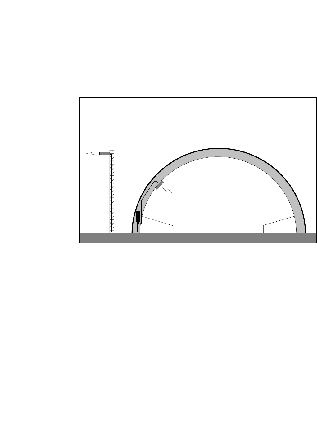
Sports Arena
A 2000 spectators sports arena with metallic roof had an indoor signal
strength too low to provide a fair service in most parts of the arena. The
nearest base station was 8 kilometers away and it was equipped with one
carrier only.
A donor antenna directed towards the base station was mounted on a
mast outside the building and a repeater was installed inside the building
with the service antenna on the arch vault. The scenario is illustrated in
Figure 2-3.
The antenna isolation was measured to over 85dB.
Measured levels: Received signal level – 80.0 dBm
Donor antenna gain 15.0 dBi
Cable loss –5.0 dB
Repeater input level – 70.0 dBm
Adjusted repeater gain 75.0 dB
Repeater output level 5.0 dBm
Cable loss – 2.0 dB
Service antenna gain 7.0 dBi
Radiated output level 10.0 dBm
The signal strength was fair for service in the entire arena.
Service antenna
Donor antenna
Figure 2-3. Repeater in sports arena
Allgon Systems AB AR Repeaters Introduction
User’s Manual VD203 66/EN Rev. P1A 2000-09 2 - 5

3. Installation
Before installation, read carefully Chapter 1, Safety.
Siting the Repeater
Allgon repeaters are designed for outdoor usage. However, humidity and
temperature changes may have affect on the reliability. A preferable site
for the repeater is thus indoor, in a tempered and ventilated room.
Sunshine
If a repeater is placed outdoor and can be exposed to direct sunshine, it is
essential that the air can circulate around the repeater with no obstacle.
The operating temperature must not exceed +55°C. A shelter can be used
to shade the repeater from direct sunshine.
Shelter
Allgon repeaters are designed with a weather proof outdoor case that can
be mounted without any kind of shelter from rain, snow or hail.
If a repeater is to be opened on the site when raining, snowing, or hailing
there must be some kind of permanent or temporary shelter. This is
applicable to gentle rainfall, snowfall or hail. Limitations for very bad
weather is found in the next section.
Allgon can provide a shelter designed for these repeaters. This shelter is
shown in Figure 3-1.
Outdoor Installation and Service Limitations
Sited outdoors, the repeater must not be opened for installation or
service at bad weather, such as:
–Intense rainfall, snowfall or hail
–Storm or high wind
–Extremely low or high temperature
–High humidity of the air
Allgon Systems AB AR Repeaters Installation
User’s Manual VD203 66/EN Rev. P1A 2000-09 3 - 1
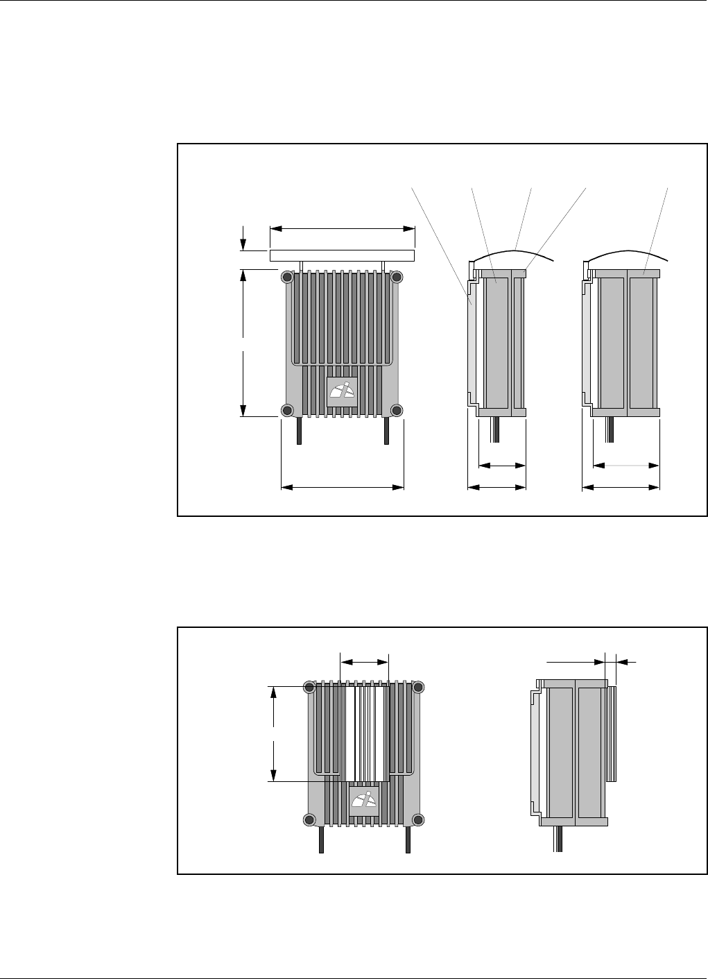
Dimensions and Weights
The dimensions of the repeater, including the mounting bracket, is shown
in Figure 3-1. The repeater chassis consists of two main parts, a cabinet
in which the circuitry is housed, and a cover, which can be either a thin
cover or a large cover (see the figure) depending on the configuration.
The high power CDMA repeater has an external heat sink on a large
cover, see Figure 3-2.
440 (17.3")
530 (20.9")
520 (20.5"
)
110 (4.3")
ALLGON
174 (6.9")
224 (8.8")
240 (9.4")
290 (11.4")
Mounting bracket Cabinet Shelter Thin cover Large cover
Figure 3-1. Repeater dimensions
ALLGON
180 (7.1")
350 (13.8")
35 (1.4")
Figure 3-2. High power CDMA repeater
Installation AR Repeaters Allgon Systems AB
3 - 2 Rev. P1A 2000-09 User’s Manual VD203 66/EN

Approximately repeater weights
Channel selective repeater, four channels, thin cover ............ 21 kg (46 lbs)
Channel selective repeater, four channels, large cover ........... 25 kg (55 lbs)
Band selective repeater, thin cover .......................................... 21 kg (46 lbs)
Band selective repeater, large cover ......................................... 25 kg (55 lbs)
Channel/band selective combi repeater, large cover ............... 30 kg (66 lbs)
Channel selective high power CDMA repeater, large cover ... 30 kg (66 lbs)
It is not recommended to remove the cover from the cabinet at the site.
However, if the cover, for some reason, has to be removed from the
cabinet, then disconnect the interconnection cables, close the cover,
remove the hinge shafts, and remove the cover.
The cabinet and cover weights are, approximately, as follows:
Empty thin cover .......................................................................... 6 kg (13 lbs)
Empty large cover ...................................................................... 10 kg (22 lbs)
Equipped cabinet or large cover ............................................... 15 kg (33 lbs)
Allgon Systems AB AR Repeaters Installation
User’s Manual VD203 66/EN Rev. P1A 2000-09 3 - 3
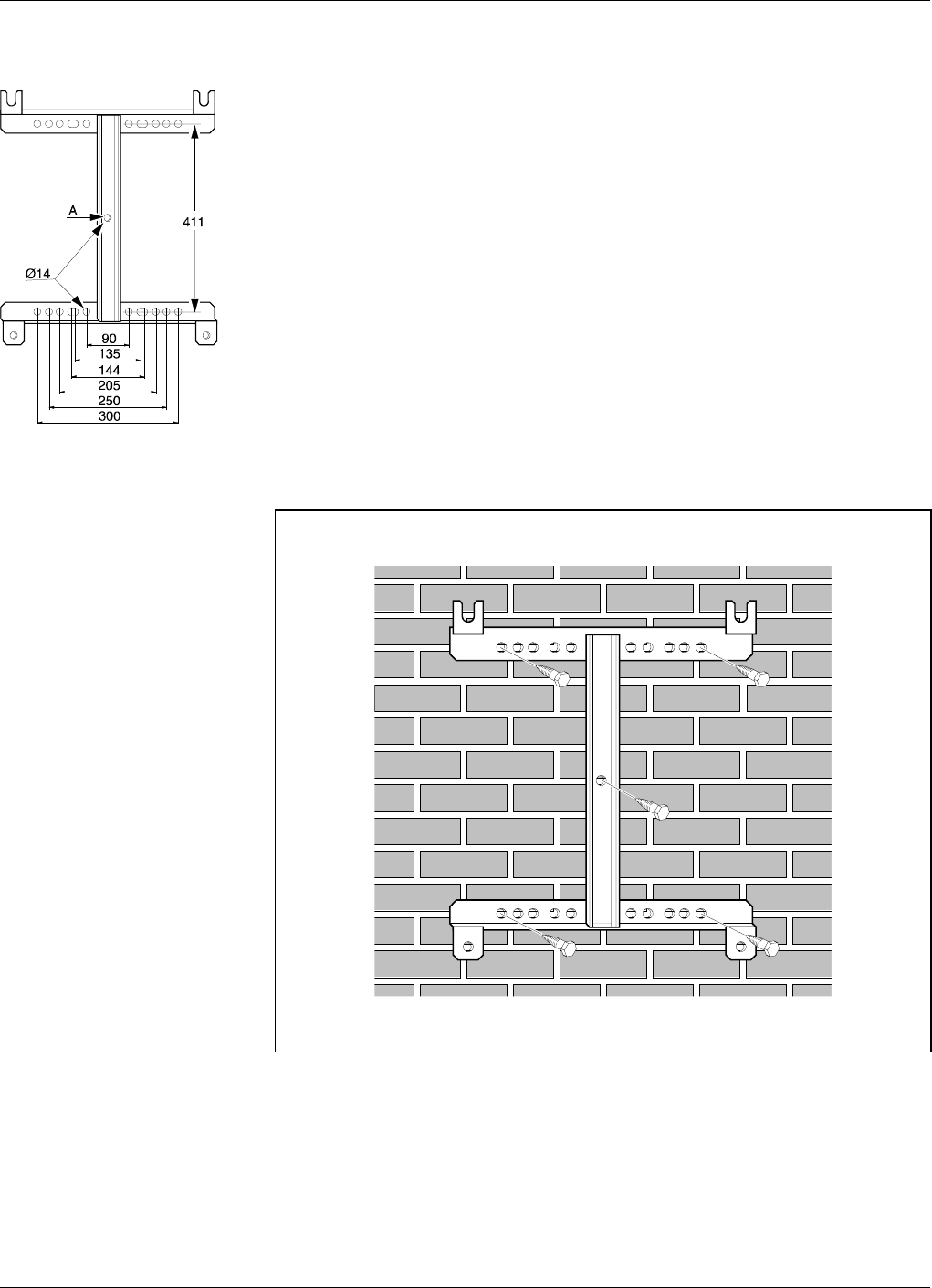
Mounting
The AR repeater is easy to mount using the provided mounting bracket,
which has Ø14mm (9/16") holes for 10mm (3/8") or 12mm (1/2") fixing
screws. Clamps with c-c measures of 90mm (3.5"), 135mm (5.3"), 144mm
(5.7"), 205mm (8.1"), 250mm (9.8"), and 300mm (11.8") can be used as
well. The vertical c-c measure for these are 411mm (16.2").
The mounting bracket is shown in the figure.
NOTE! There is a Ø14mm (9/16") single hole in the middle of the
mounting bracket, marked ’A’ in the figure, which is intended for a
locking screw, i.e. a screw which cannot be removed when the repeater is
put in the bracket.
Mount the repeater as follows:
1. Mount the provided bracket.
Normally, the repeater is mounted on a wall, pole, or mast. These
mounting cases are shown below.
Figure 3-3 shows a bracket attachment to a wall using four fixing
screws and a locking screw.
Figure 3-3. Attaching the bracket to a wall
Installation AR Repeaters Allgon Systems AB
3 - 4 Rev. P1A 2000-09 User’s Manual VD203 66/EN
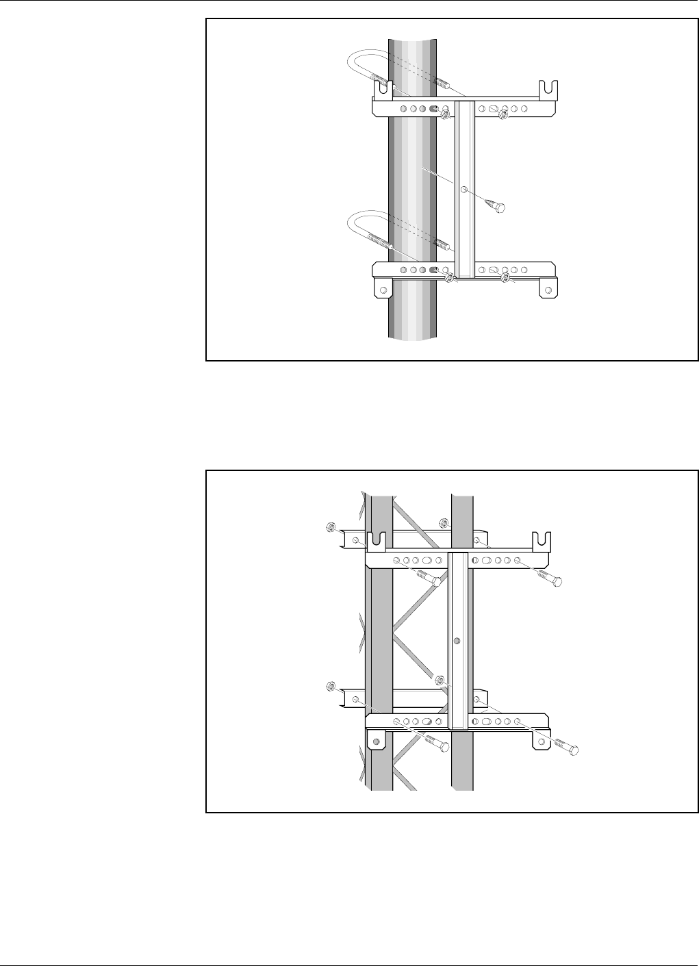
Figure 3-4 shows a bracket attachment to a pole using two 144mm
(5.7") U-shaped clamps and a locking screw.
Figure 3-5 shows a bracket attachment to a mast using two 300mm
(11.8") bar-shaped clamps and no locking screw.
Figure 3-4. Attaching the bracket to a pole
Figure 3-5. Attaching the bracket to a mast
Allgon Systems AB AR Repeaters Installation
User’s Manual VD203 66/EN Rev. P1A 2000-09 3 - 5
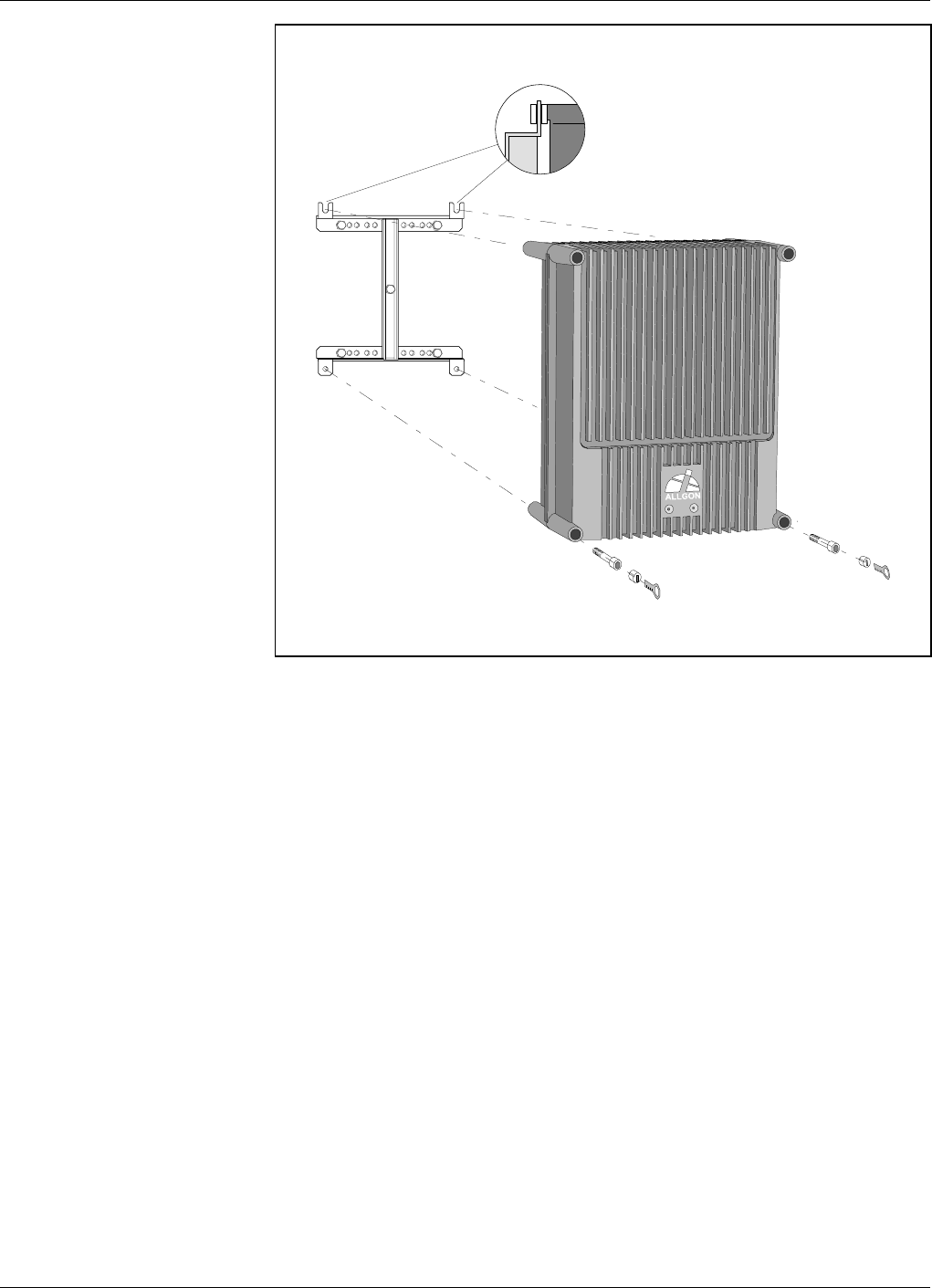
2. After attaching the bracket, hang the repeater on the upper supports
(see Figure 3-6) and use the screws for the lower ones. Tighten the
upper and lower screws.
There are locking cylinders that can be inserted and locked with a
key after the lower screws have been tightened (see Figure 3-6).
These prevents from unauthorized removal of the repeater.
3. Mount the donor antenna directed towards the base station antenna.
This antenna is marked ’BS’ in the repeater.
4. Mount the service antenna directed towards the area to be covered by
the repeater. This antenna is marked ’MS’ in the repeater.
Figure 3-6. Attaching the repeater to the bracket
Installation AR Repeaters Allgon Systems AB
3 - 6 Rev. P1A 2000-09 User’s Manual VD203 66/EN
Connection
1. Connect the service and donor antenna coaxial cables (see
Figure 3-7). N type female connectors are used in the repeater.
The donor antenna (BS) is connected to the right in the cabinet,
except for the high power CDMA repeater for which the donor
antenna is connected to the left in the cabinet (see Figure 3-7).
The service antenna (MS) is connected to the left in cabinet, except
for the high power CDMA repeater for which the service antenna is
connected to the right in the cabinet (see Figure 3-7).
2. Mount the mains plug and connect the power supply unit, PSU.
For repeaters supplied from the mains, the mains outlet must be
grounded. Both the mains plugs of repeaters equipped with two power
supply units must be connected to outlets supplied from the same fuse.
MS
DPX
ANT
TEST
DC
-30 dB
-20 dB
MS
DPX
ANT
TEST
DC
-30 dB
-20 dB
OUT
LOW IN ATT +7V OUT1 OUT2
LNA
UL OUT
LOWIN+7V ATTOUT1 OUT2
LNA
DL
MS BS
BS MS
Mains
High power CDMA only
PSU
Figure 3-7. MS and BS antenna connections
Allgon Systems AB AR Repeaters Installation
User’s Manual VD203 66/EN Rev. P1A 2000-09 3 - 7
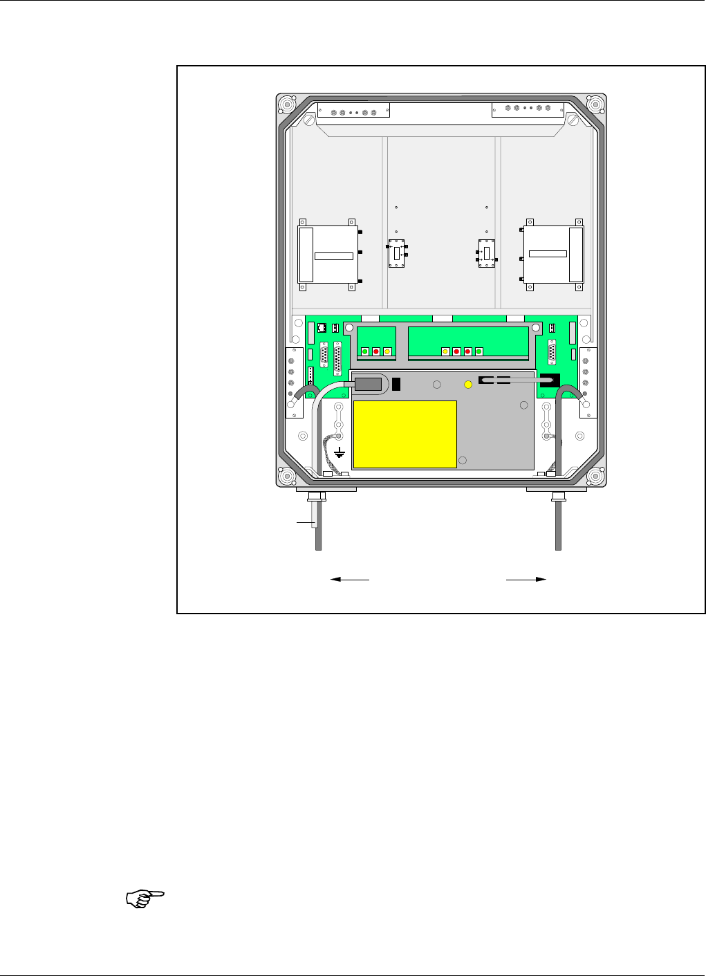
3. Connect external alarm sensors (burglary, fire, etc.) and other
external alarm equipment (optical or acoustic signal, etc.), if any.
External alarm is connected to the P33 alarm port located to the left
in the cabinet (see Figure 3-8 on page 3-10). Use a 15 pole D-sub
male connector.
The P33 port is described on page 3-12.
Cables for this installation is taken through strain relief bushings or
connectors at the bottom of the repeater.
This is a schematic figure.
The various RCU parts can
be integrated or configured
differently.
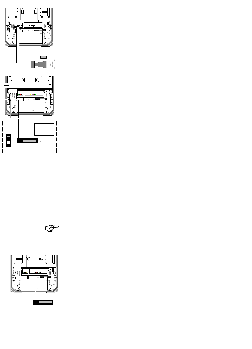
4. Connect the internal phone/modem unit for remote control of the
repeater, if any.
The modem and a power backup unit are integrated in an RCU,
Remote Control Unit, which is mounted downmost inside the cabinet,
in front of the PSU. The RCU is available in different types for
various systems, which is further detailed in the Optionals section in
Chapter 6.
The modem is connected to the P32 modem port (RS-232, V.24
interface) on the repeater located to the left in the cabinet (see
Figure 3-8 on page 3-10).
The P32 port is described on page 3-12.
The mobile phone antenna is connected to the MS –20dB port on the
BS directional coupler (DC) in the cabinet (DC/BS), provided that the
phone and the repeater operate in the same system.
If an RCU is used, this is powered by the P27 auxiliary port located
to the left in the cabinet (see Figure 3-8 on page 3-10). Pin 2 and 3
of the P27 port are interconnected with a jumper if not used. This
jumper must be removed before plugging the RCU connector to P27.
The P27 port is described on page 3-11.
If the RCU is removed, the jumper between pin 2 and 3 on the P27
port must be reconnected. Otherwise, the CU and ALI boards will
have no voltage supply. Do not connect the jumper to another position
than between pin 2 and 3 on the P27 port.
5. Connect a telephone line for remote control of the repeater, if any.
The telephone line is connected to a modem, which is connected to
the P32 modem port on the repeater.
The P32 port is described on page 3-12.
Use a strain relief bushing or a connector at the bottom of the
repeater for the external telephone line cable.
P33
External alarm
sensors
P32
P27
RCU
MS –20dB
Modem
Battery
Power supply
P32
Telephone line Modem
Installation AR Repeaters Allgon Systems AB
3 - 8 Rev. P1A 2000-09 User’s Manual VD203 66/EN
6. Connect the Repeater to Repeater Link cable, if this optional feature
is to be used. The R2R net cable is connected to the P34 Repeater to
Repeater Link port via the P1 terminal on the R2R connector board
to the right in the repeater.
The P34 Repeater to Repeater Link port is described on page 3-14.
Use a strain relief bushing or a connector at the bottom of the
repeater for the external telephone line cable.
Required information for a Repeater to Repeater Link installation is
found in the VD202 91/EN, R2R, Repeater to Repeater Link Kit,
Installation Guide.
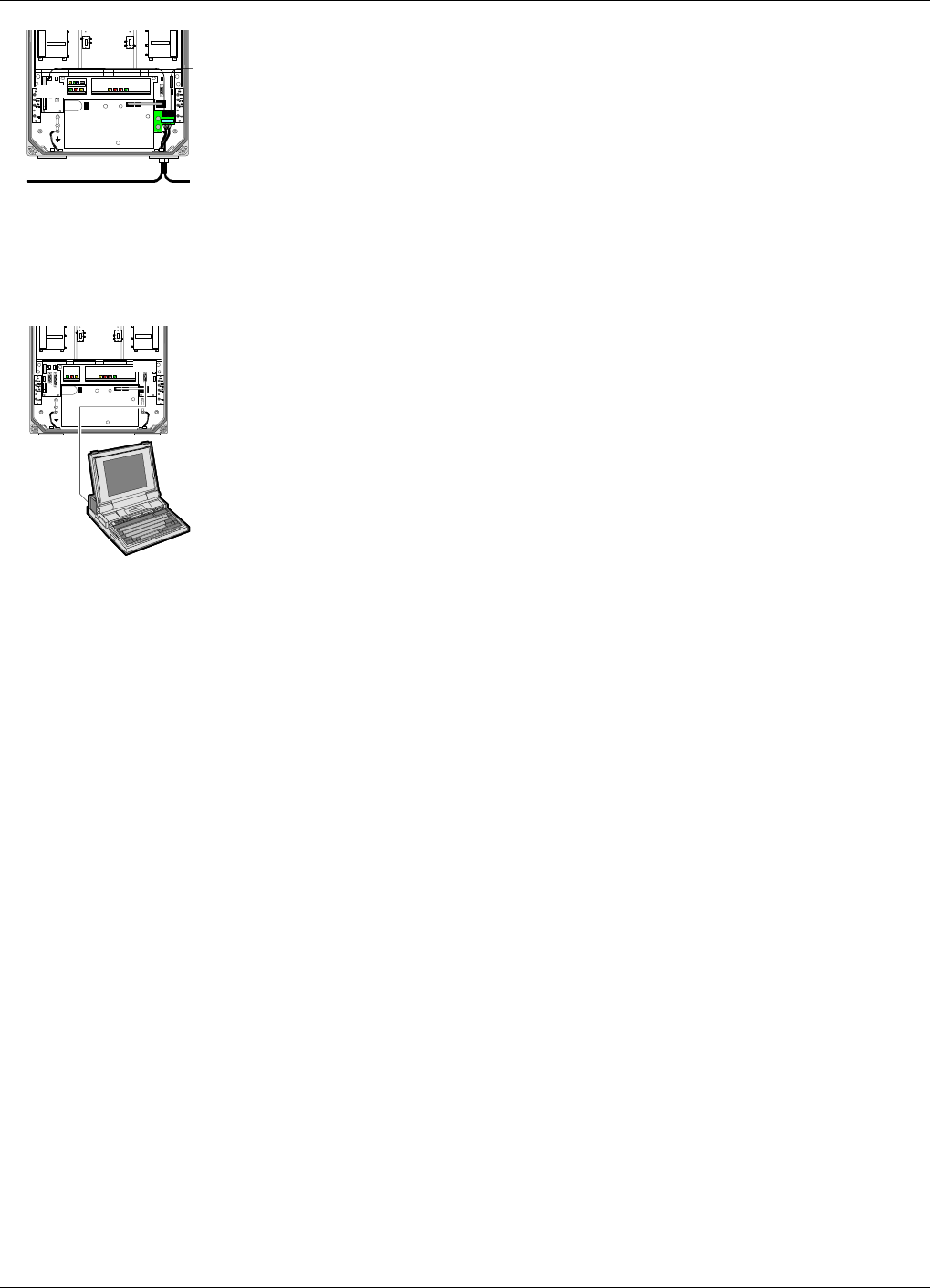
7. Connect a PC for controlling the repeater. A COM port on the PC is
connected to the P31 PC port (RS-232) located to the right in the
cabinet (see Figure 3-8 on page 3-10). Use the provided serial cable.
Port P31 is described on page 3-11.
Now, you can use OMT32 to set up and control the repeater. The
OMT32 program is described in the OMT32, User’s Manual.
But first, check the connections made and commission the repeater as
described in Chapter 4.
P34
P3 P2
P1
P31
Allgon Systems AB AR Repeaters Installation
User’s Manual VD203 66/EN Rev. P1A 2000-09 3 - 9
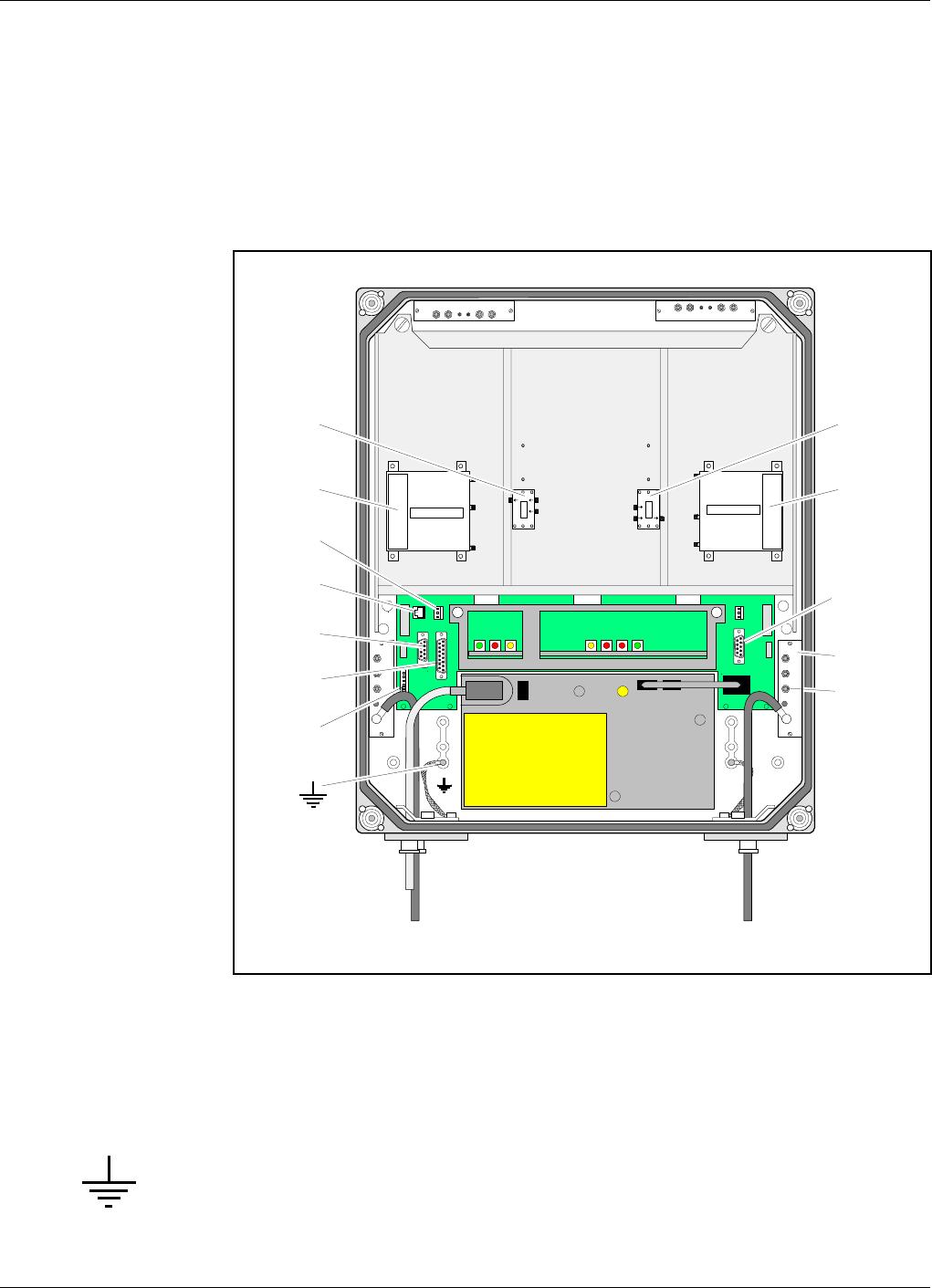
Connection Ports and Station Ground
The DIA distribution board provides most of the internal connection
between the repeater units, and to external ports. Connectors involved in
the installation are also located on the DIA board. These connectors are
described below. A complete DIA board connector list is found in the
Board and Unit Descriptions section in Chapter 5.
Station ground is detailed below as well.
Station Ground
There is a ground screw (M8) in the repeater that is intended for station
ground (see Figure 3-8). This screw must be used only for station
grounding.
MS
DPX
ANT
TEST
DC
-30 dB
-20 dB
MS
DPX
ANT
TEST
DC
-30 dB
-20 dB
OUT
LOW IN ATT +7V OUT1 OUT2
LNA
UL OUT
LOWIN+7V ATTOUT1 OUT2
LNA
DL
MS BS
DPX DPX
MS BS
CMB CMB
DL UL
P33
P27
P31
DC
MS
-20 dB
P32
P28
P34
Figure 3-8. Connection ports and station ground
Installation AR Repeaters Allgon Systems AB
3 - 10 Rev. P1A 2000-09 User’s Manual VD203 66/EN
P27 Auxiliary Port
Auxiliary port P27 is used for powering an RCU mobile phone/modem
remote control unit. The connector is found on the DIA board to the left
in the cabinet (see Figure 3-8).
P27 is an 8 pole, 1 line male connector.
Pin 2 and 3 of the P27 port MUST ALWAYS be interconnected to provide
the CU and ALI boards with voltage supply. If there is no cable connected
to the P27 port, pin 2 and 3 MUST be interconnected with a jumper.
P27 auxiliary connector pinning
Pin 1 +7V DC
Pin 2 +7V DC
Pin 3 CU and ALI power supply from pin 2
Pin 4 GND
Pin 5 +26V DC or +10V DC depending on the repeater type
Pin 6 Not used
Pin 7 Output 200KHz reference
Pin 8 GND
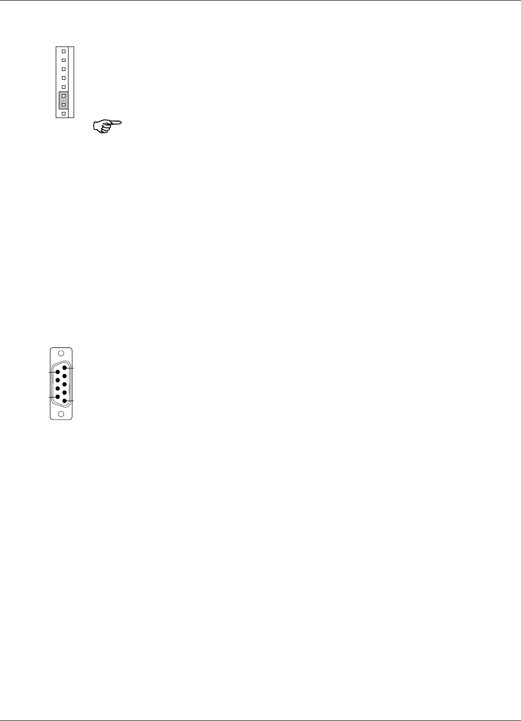
P31 PC Port
PC port P31 is a RS-232 port used for local PC communication.
The connector is found on the DIA board to the right in the cabinet (see
Figure 3-8).
P31 is a 9 pole D-sub female connector.
P31 PC connector pinning
Pin 1 Not used
Pin 2 Data from repeater to OMT32
Pin 3 Data from OMT32 to repeater
Pin 4 DTR from OMT32 to repeater
Pin 5 GND
Pin 6 DSR from repeater to OMT32
Pin 7 RTS from OMT32 to repeater
Pin 8 CTS from repeater to OMT32
Pin 9 Not used
1
8
6
5
9
1
Allgon Systems AB AR Repeaters Installation
User’s Manual VD203 66/EN Rev. P1A 2000-09 3 - 11
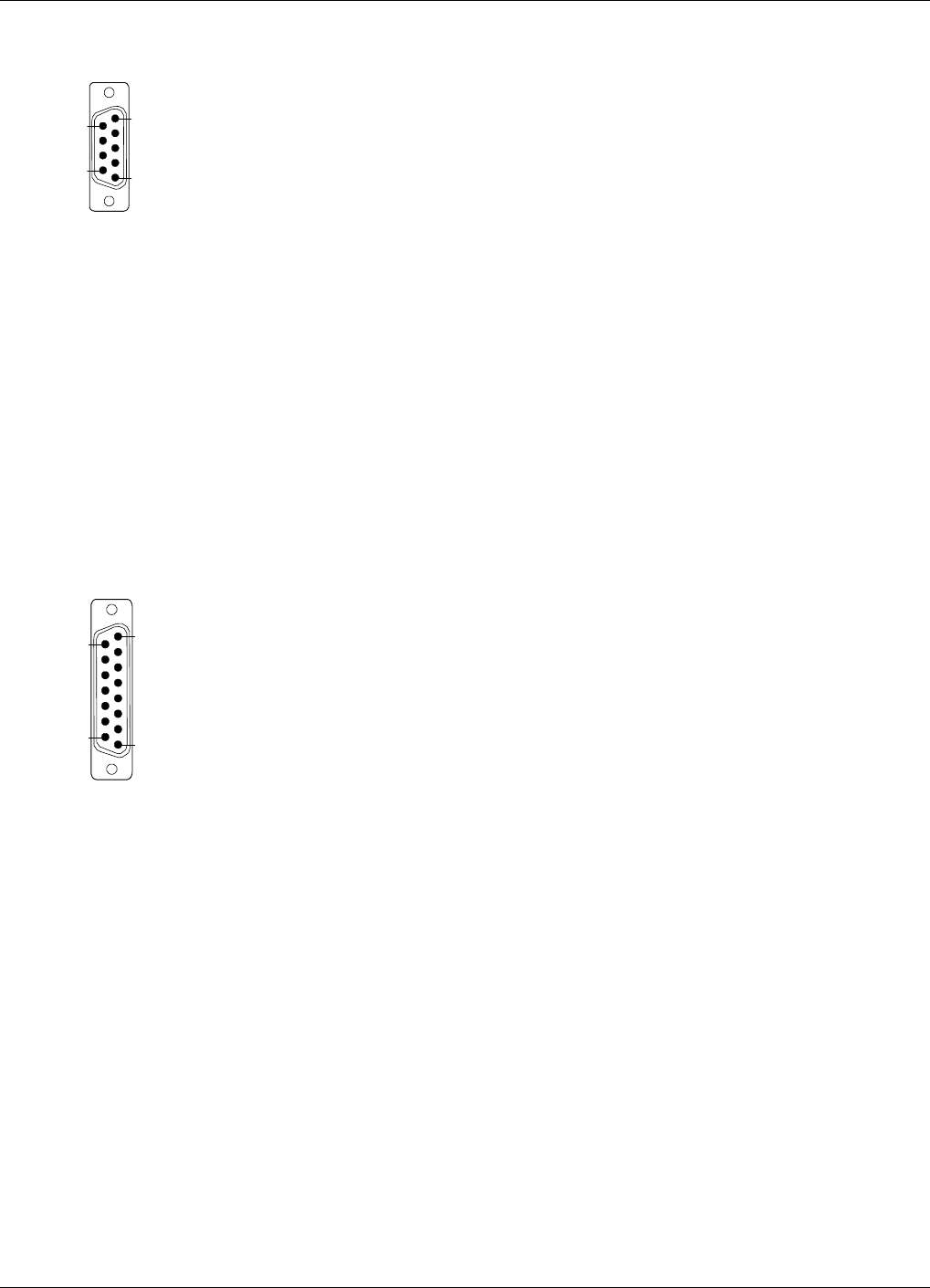
P32 Modem Port
Modem port P32 is a RS-232 port with V.24 interface used for remote
control of the repeater.
The connector is found on the DIA board to the left in the cabinet (see
Figure 3-8).
P32 is a 9 pole D-sub male connector.
P32 modem connector pinning
Pin 1 DCD
Pin 2 RXD
Pin 3 TXD
Pin 4 DTR
Pin 5 GND
Pin 6 DSR
Pin 7 RTS
Pin 8 RFS
Pin 9 RI
P33 Alarm Port
Alarm port P33 is used for external alarm sensors and alarm equipment.
The connector is found on the DIA board to the left in the cabinet (see
Figure 3-8).
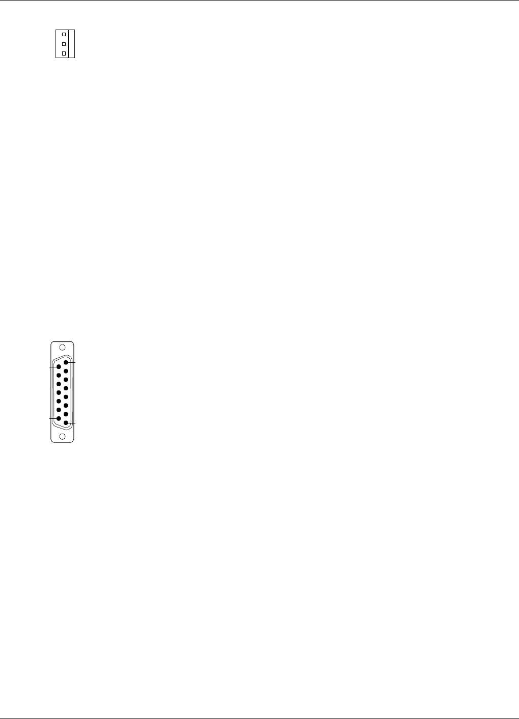
P33 is a 15 pole D-sub female connector.
The port has four alarm inputs, EAL1 - EAL4, and two alarm outputs.
Four alarm inputs
The inputs are low-level inputs (signal AI1 - AI4) with common ground
(AIC).
Use insulated switch or relay to initiate alarms (open switches in normal
operating mode, closed switches cause alarm).
The alarm switch connection can be toggled between being active open or
active closed. See the Alarm Configuration section in Chapter 11.
The alarm input voltage ratings, related to ground (AIC), are:
Vinmax = 5.5V
Vinmin =–0.5V
The alarm inputs are defined as follows:
Pin 14 AI1 External alarm input 1 - EAL1
Pin 15 AI2 External alarm input 2 - EAL2
Pin 7 AI3 External alarm input 3 - EAL3
Pin 8 AI4 External alarm input 4 - EAL4
Pin 6 AIC Ground
6
5
9
1
15 8
1
9
Installation AR Repeaters Allgon Systems AB
3 - 12 Rev. P1A 2000-09 User’s Manual VD203 66/EN
P28 - AI4 door switch alarm input
Normally, alarm input AI4 is used for repeater cover opening alarm
EAL4, which is arranged using a door switch (optional). Because of that,
AI4 and AIC are available also in the P28 connector, to which the door
switch is connected. The location of the connector in the cabinet is shown
in Figure 3-8.
The EAL4 door switch alarm is activated 10-30 seconds after the cover
has been opened.
Two alarm outputs
Both the alarm outputs are 1 pole closing and 1 pole opening relay
outputs insulated from each other.
Maximum ratings, related to ground or any other alarm terminal, are
50VAC/60VDC.
The alarm outputs are defined as follows:
Pin 9-1 AO1-AO8 Closed when operating, otherwise open
Pin 10-2 AO6-AO7 Open when operating, otherwise closed
Pin 11-3 AO2-AO5 Closed at alarm state, otherwise open
Pin 12-4 AO3-AO4 Open at alarm state, otherwise closed
P33 alarm connector pinning
Pin 1 AO8
Pin 2 AO7
Pin 3 AO5
Pin 4 AO4
Pin 5 Not used
Pin 6 AIC
Pin 7 AI3
Pin 8 AI4
Pin 9 AO1
Pin 10 AO6
Pin 11 AO2
Pin 12 AO3
Pin 13 Not used
Pin 14 AI1
Pin 15 AI2
1
3
15 8
1
9
Allgon Systems AB AR Repeaters Installation
User’s Manual VD203 66/EN Rev. P1A 2000-09 3 - 13

P34 Repeater to Repeater Link Port
The P34 port is used for Repeater to Repeater Link (R2R net), which is an
optional feature for the AR repeaters.
The connector is found on the DIA board to the left in the cabinet (see
Figure 3-8).
P34 is an 8 pole RJ45 modular female connector.
P34 Repeater to Repeater Link connector pinning
Pin 1 C/S
Pin 2 GND
Pin 3 D–
Pin 4 D+
Pin 5 D+
Pin 6 D–
Pin 7 GND
Pin 8 C/S
For further information about the Repeater to Repeater Link installation,
refer to the VD202 91/EN R2R, Repeater to Repeater Link Kit, Installation
Guide.
Installation AR Repeaters Allgon Systems AB
3 - 14 Rev. P1A 2000-09 User’s Manual VD203 66/EN
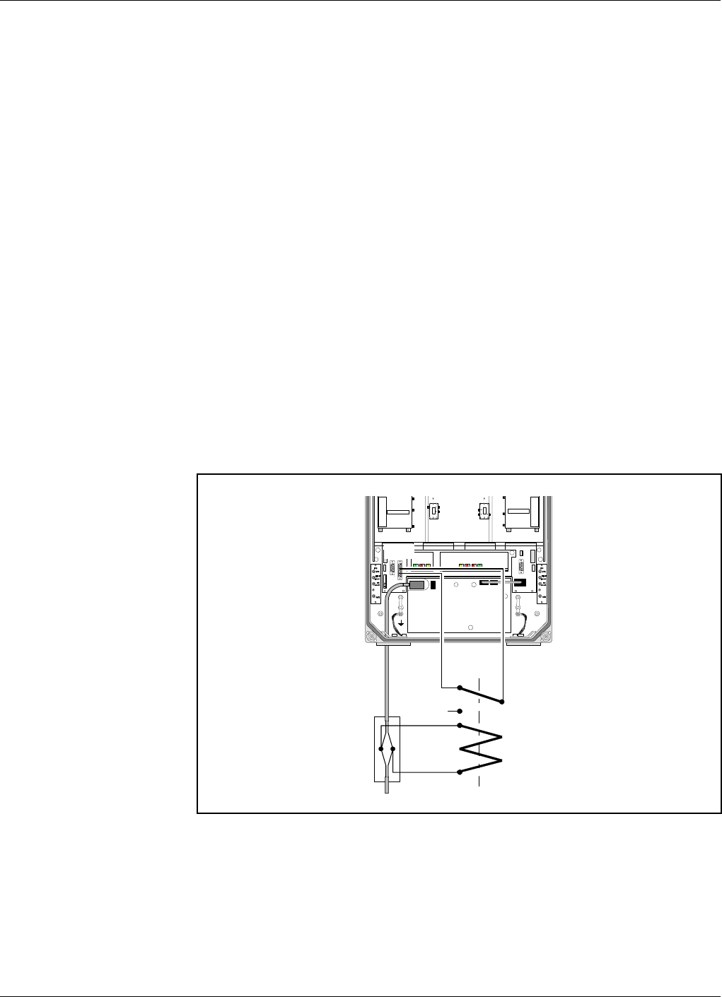
Mains Breakdown Relay
To be able to distinguish PSU faults from power failure, a mains
breakdown relay must be used on the repeater mains supply.
The mains breakdown relay is not included in the repeater. So, it has to
be mounted outside the repeater chassis. The relay intended for this
purpose must fulfil the following specifications:
Relay specification
Closing time: max. 30 milliseconds
Insulation coil/contact: min. 4KV
Mains connected relay must be in compliance with valid local regulations.
Connection
•Connect a currentless closed relay contact to pin AI1 and AIC on the
P33 alarm connector see Figure 3-9. Alarm is initiated by short
circuiting pin AI1 and AIC in the P33 connector. The P33 alarm
connector is detailed on page 3-12.
•Connect the relay coil. It must be supplied from the same fuse as the
repeater.
•After commissioning, select the Mains breakdown option in the
Alarm Configuration dialog box described in the Alarm Configuration
section in Chapter 11.
P33
P33:AI
C
P33:AI1
Figure 3-9. Mains breakdown relay connection
Allgon Systems AB AR Repeaters Installation
User’s Manual VD203 66/EN Rev. P1A 2000-09 3 - 15
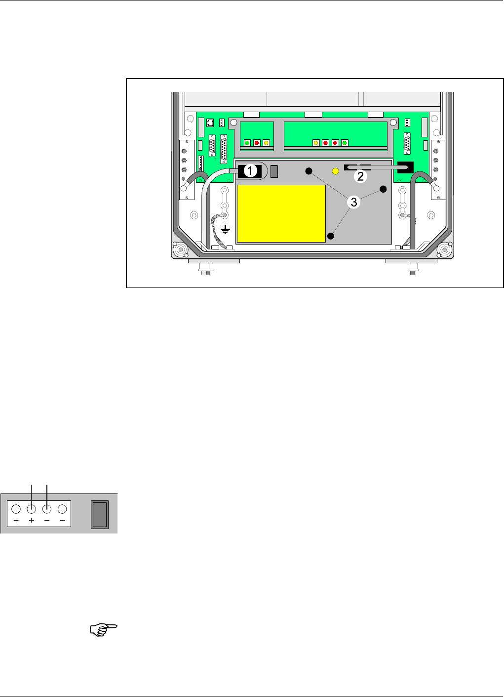
Installing 24 Volt or 48 Volt DC Power Supply Unit
You can replace the 220V AC PSU with a 24 Volt or 48 Volt DC PSU as
follows:
1. Switch the repeater off and remove the mains plug from the PSU
(’1’ in Figure 3-10).
2. Disconnect the two connectors (2) on the PSU.
3. Loosen the three fixing screws (3) using a 5mm Allen key.
4. Remove the PSU from the repeater.
5. Mount the 24/48 Volt DC PSU with the three fixing screws (3).
6. Connect the PSU to the DIA board (2).
7. Connect the DC power cable. The supplied cable should have a
radiation limiter. The cable shall be connected as follows:
The + pole shall be connected to one of the left terminals in the PSU
connector with the BROWN part of the DC cable.
The – pole shall be connected to one of the right terminals in the
PSU connector with the BLUE part of the DC cable.
8. Switch the repeater on.
9. The yellow LED on the PSU shall now be lit.
The DC Power Supply Unit must be galvanically separated from the mains
supply with an equipment fulfilling the IEC65 safety requirements.
MS
DPX
ANT
TEST
DC
-30 dB
-20 dB
MS
DPX
ANT
TEST
DC
-30 dB
-20 dB
Figure 3-10. Replacing the PSU
BROWN BLUE
Installation AR Repeaters Allgon Systems AB
3 - 16 Rev. P1A 2000-09 User’s Manual VD203 66/EN

4. Commissioning
Read carefully Chapter 1 Safety before commissioning the repeater.
Check all connections made during the installation. Also, ensure that
both the mains plugs for repeaters equipped with two power supply units
are connected to outlets supplied from the same fuse.
To fulfill the IP65 weather protective requirements, ensure that the cable
strain relief bushings are properly tightened. Also, ensure that the gaskets
at the cable inlets and on the cabinet are properly fitted and not damaged.
When the installation is checked, commission the repeater as described
below.
Allgon Systems AB AR Repeaters Commissioning
User’s Manual VD203 66/EN Rev. P1A 2000-09 4 - 1

Starting the Repeater
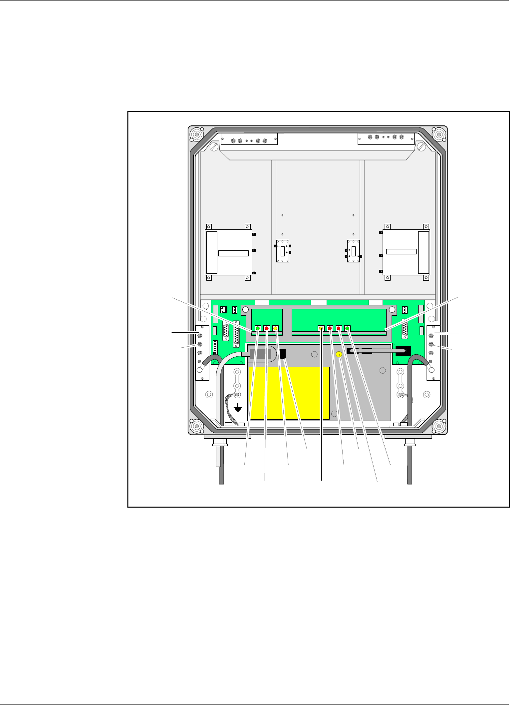
1. Turn the mains switch on (marked ’S’ in Figure 4-1).
2. Check the LED on the power supply unit (V). It must be lit with a
steady yellow light.
3. Check the four CU board LEDs (see Figure 4-1). A correct power
up is indicated as follows:
PWR
Yellow LED which is lit with a steady light after the mains is
switched on. Indicates present power.
BOOT
Red LED that is lit with a steady light when the system boots, i.e. for
10 - 15 seconds after the mains is switched on. Then, it flashes for
the next 5 - 10 seconds. After that, if no error is detected, the LED
is off.
ALARM
Red LED that flashes 15 - 20 seconds after the mains is switched on.
Then, it flashes for less serious alarms (ERROR) and is lit with a
steady light for fatal alarms (CRITICAL).
OPER
Green LED that lights up approx. 15 seconds after the mains is
switched on. It shows, with a steady light, that the repeater is ready
for operation.
4. Check the three ALI board LEDs (see Figure 4-1). The LEDs follow
the alarm relays. A correct power up is indicated as follows:
OPER
Green LED that has the same indication as the green LED on the CU
board (see above).
ALARM
Red LED that is lit with a steady light for ERROR and CRITICAL
alarms.
PWR
Yellow LED that has the same indication as the yellow LED on the
CU board (see above).
External indicators on the repeater front
Yellow
Operation LED that lights up approx. 15 seconds after the mains is
switched on. At steady light the repeater is ready for operation.
Red
Alarm LED that indicates ERROR alarms with flashing light and
CRITICAL alarms with steady light.
Commissioning AR Repeaters Allgon Systems AB
4 - 2 Rev. P1A 2000-09 User’s Manual VD203 66/EN
When the indicators show operational mode, the repeater can be
configured for operation by using a computer running OMT32. This is
further detailed in the OMT32, User’s Manual.
Indicators
Figure 4-1 shows the repeater indicators and the mains switch. There are
also two external indicators on the repeater front cover.
Repeater to Repeater Link
indicators Additional indicators are found in the repeater, if equipped with the
Repeater to Repeater Link feature. For information about these indicators,
refer to the VD202 91/EN R2R, Repeater to Repeater Link Kit, Installation
Guide.
MS
DPX
ANT
TEST
DC
-30 dB
-20 dB
MS
DPX
ANT
TEST
DC
-30 dB
-20 dB
OUT
LOW IN ATT +7V OUT1 OUT2
LNA
UL OUT
LOWIN+7V ATTOUT1 OUT2
LNA
DL
OPER
ALARM
PWR
PWR
BOOT
ALARM
OPER
CU
ALI
S
DC
TEST
-30 dB
MS
DC
TEST
-30 dB
BS
V
Figure 4-1. Indicators and mains switch
Allgon Systems AB AR Repeaters Commissioning
User’s Manual VD203 66/EN Rev. P1A 2000-09 4 - 3

Measuring the Output Power Level
Uplink and downlink output power test ports are found on the directional
couplers (DC) at the MS and BS antenna connectors. These test ports are
marked TEST –30dB (see Figure 4-1) and are intended for measuring
using e.g. a spectrum analyzer.
The coupling is –30dB approximately. There is no directivity in these test
ports, i.e. both uplink and downlink signal can be measured.
Voltage Supply Testpoints
A number of voltage supply testpoints are available in the repeater.
These testpoints are named U7A - U7F for the 7V supply voltages and
U26 for 26V, 13V or 10V supply voltage (depending on the repeater type).
A standard multi-meter can be used on these testpoints.
The testpoints are found on the DIA board in the repeater cabinet. The
testpoint positions on the DIA board is detailed in the Board and Unit
Descriptions section in Chapter 5.
If the repeater is equipped with a second PSU, e.g. for combined
channel/band selective operation, the same set of testpoints are also found
on the cover DIA board.
Repeater Configuration
The repeater is now ready to be configured in accordance with the site
conditions and system performance requirements. Pay especial attention
to the antenna isolation described in the OMT32, User’s Manual.
Commissioning AR Repeaters Allgon Systems AB
4 - 4 Rev. P1A 2000-09 User’s Manual VD203 66/EN

5. Functional Description
Allgon repeaters work as bi-directional on-frequency amplifiers.
A repeater receives, amplifies, and retransmits signals downlink and
uplink simultaneously, i.e. from the base station via the repeater to the
mobile stations and from the mobile stations via the repeater to the base
station.
The repeater is connected to a BS antenna, directed towards the base
station, and to a MS antenna directed towards the area to be covered.
These antennas are connected to the repeater with N type male
connectors.
To prevent instability due to poor antenna isolation, a built-in antenna
isolation supervision feature reduces the gain level automatically when
poor antenna isolation is detected.
The Allgon repeaters are controlled by powerful microprocessors.
Alarm and operational LEDs are visible on the repeater front.
The repeater works with convection cooling without fan.
Operational parameters such as gain, channel number, power levels, etc.
are set using a desktop or notebook and the Allgon OMT32, which
communicate, locally or remotely via modem, with the repeater. Remote
operation is performed using a telephone line or a built-in mobile phone
equipped with a data interface.
ALLGON System AB AR Repeaters Functional Description
User’s Manual VD203 66/EN Rev. P1A 2000-09 5 - 1

Repeater Design
The repeater is housed in a cast aluminium chassis that is waterproof,
class NEMA4/IP65, for outdoor use. The chassis has a design suited for
outdoor use as well as indoor use.
The chassis consists of a cabinet and a cover joined with hinges. The
cabinet contains the repeater circuitry. The cover can either be a thin
cover or a large cover. The latter consists of another cabinet which can
be used as an empty cover or be equipped as an independent repeater unit.
The cover has two external LEDs for operation and alarm indication.
The cabinet as well as a large cover can be equipped for channel selective
operation or band selective operation. A combined repeater is normally
equipped for channel selective operation in the cabinet and band selective
operation in the cover.
Different amplifier boards are used to get the various operations (see
below). The amplifier boards are individually shielded and located under
metal cover sheets which can be folded out.
CHA, Channel selective GSM amplifier board
Channel selective GSM repeaters can handle up to eight repeater channels
(four if the CU part number is K103/1). For every even number of
repeater channels, two CHA amplifier boards are required in the repeater,
one CHA board for uplink signaling and one board for downlink signaling.
Each repeater channel is allocated to a radio channel or switched off. In a
GSM type TDMA system (GSM, EGSM, DCS1800 or PCS1900), one
repeater channel can handle eight calls (sixteen if half-rate encoding is
used).
CSA, Channel selective CDMA amplifier board
Current CDMA repeaters can handle two CDMA repeater channels. For
every even number of repeater channels, two CSA amplifier boards and
two PA amplifier boards are required in the repeater, one pair of CSA/PA
boards for uplink signaling and one pair for downlink signaling. Each
repeater channel is allocated to a radio channel or switched off.
BSA, Band selective amplifier board
Band selective repeaters can handle one wide band repeater channel. The
band width is either fixed or adjustable (fixed for 900MHz repeaters only).
A band selective repeater channel requires two BSA boards and two PA
amplifier boards in the repeater. One pair of BSA/PA boards for uplink
signaling and one pair for downlink signaling.
BA, High power CDMA booster amplifier board
CDMA repeaters can be equipped with a high power booster amplifier
board that boosts the output gain with typically 6dB. A high power
CDMA repeater can operate with maximum 2 channels.
Functional Description AR Repeaters ALLGON System AB
5 - 2 Rev. P1A 2000-09 User’s Manual VD203 66/EN

Other units
In addition to the channel/band selective boards, the repeater contains:
•DIA Distribution board, which is a board on which all other boards and
units are connected to.
On the DIA board, there is a shielded metal frame in which the CU and
ALI boards are located.
There is a DIA board in the cabinet, and another board in the cover, if
equipped.
•CU Control Unit board, located in the frame on the DIA board.
There is one CU board in the cabinet, which controls the entire
repeater.
•ALI Alarm Interface board, located in the frame on the DIA board.
There is one ALI board in the cabinet which handles alarm and alarm
communication.
•DC Directional Coupler, located in shielded boxes which are formed as
recesses in the cabinet.
Two DC units in the cabinet are used as antenna signal directional
coupler.
•LNA Low Noise Amplifier, located in shielded boxes which are formed
as recesses in the cabinet.
Two LNA units in the cabinet are used as downlink and uplink low
noise amplifiers, and additional two LNA are used in the cover, if
equipped.
•DPX Duplex filter, located on the cover plate over the channel/band
selective boards.
•CMB Combiner unit, located on the cover plate over the channel/band
selective boards in channel selective repeaters with more than two
channels, and in combined repeaters.
•RCU unit (optional), see Chapter 6, Optionals.
•PSU Power Supply Unit, located downmost in the cabinet, and in the
cover, if equipped.
If the repeater is equipped with an optional Repeater to Repeater Link
feature, the following board is also included in the repeater (not valid to
channel selective CDMA repeaters):
•RIA Repeater to Repeater Interface Adapter, located in the frame on
the DIA board.
For further information about the Repeater to Repeater Link feature,
refer to the VD202 91/EN R2R, Repeater to Repeater Link Kit,
Installation Guide.
ALLGON System AB AR Repeaters Functional Description
User’s Manual VD203 66/EN Rev. P1A 2000-09 5 - 3
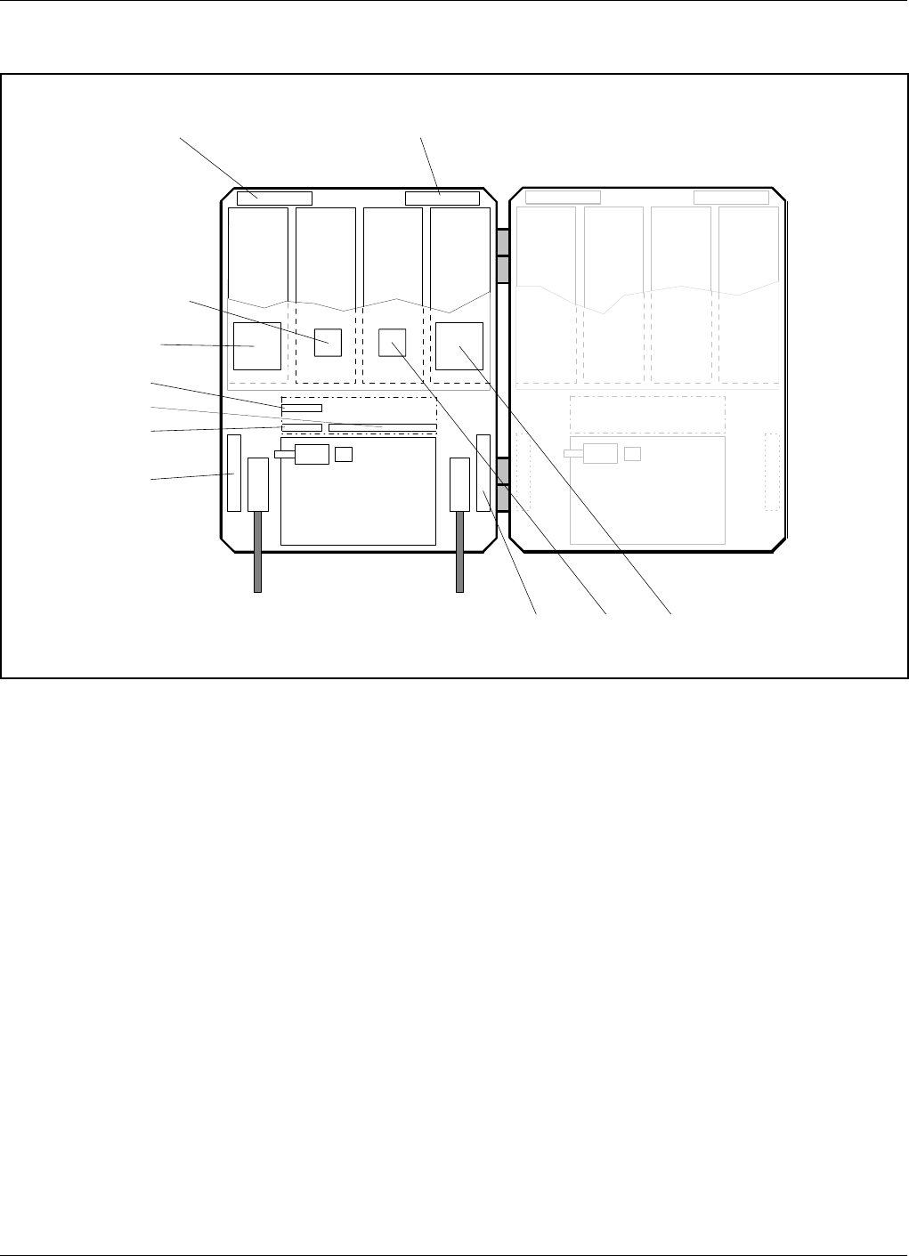
Channel Selective GSM Repeater
A cabinet (the left part in Figure 5-1) for a channel selective GSM
repeater can be equipped with four CHA channel boards, two downlink
boards (DL) with two internal channels each and two uplink boards (UL)
with two internal channels each. The described cabinet has a capacity of
four bi-directional GSM channels.
The cover (the right part in Figure 5-1) can be equipped as well, which
gives up to eight GSM channels. The cover board positions are shown in
the figure.
Channel selective GSM repeaters are used for GSM, DCS and PCS types
of TDMA systems.
Main units: ALI Alarm Interface board
CHA Channel Selective Amplifier board, GSM type
CMB Combiner unit
CU Control Unit board
DC Directional Coupler
DPX Duplex filter
LNA Low Noise Amplifier
PSU Power Supply Unit
RIA Repeater to Repeater Interface Adapter (optional)
123 4 567 8
CHA1
DL
(2 ch.)
MS
Mobile station
antenna
BS
Base station
antenna
CHA2
DL
(2 ch.)
CHA3
UL
(2 ch.)
CHA4
UL
(2 ch.)
LNA DL
Downlink
LNA UL
Uplink
CMB
Downlink
DPX
MS
CU
ALI
DC
MS
DC
BS CMB
Uplink DPX
BS
PSU
RIA
CHA5
DL
(2 ch.)
CHA6
DL
(2 ch.)
CHA7
UL
(2 ch.)
CHA8
UL
(2 ch.)
Figure 5-1. Channel selective GSM repeater
Functional Description AR Repeaters ALLGON System AB
5 - 4 Rev. P1A 2000-09 User’s Manual VD203 66/EN
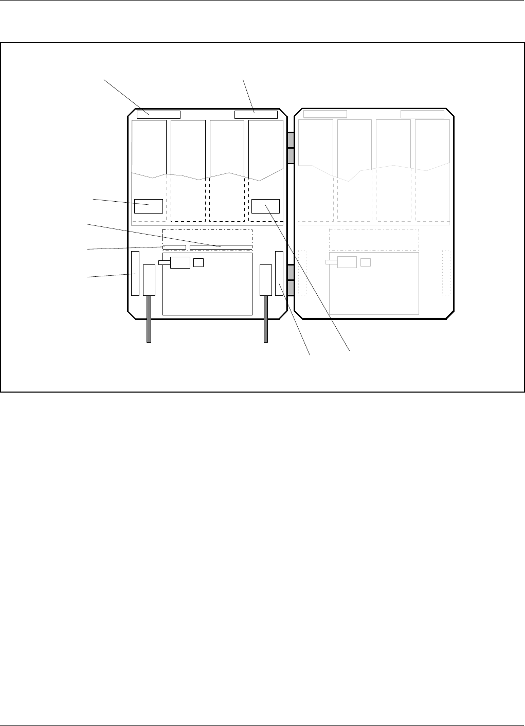
Channel Selective CDMA Repeater
A cabinet (the left part in Figure 5-2) for a channel selective CDMA
repeater can be equipped with two pair of CSA and PA boards, one pair
for downlink (DL) and one pair for uplink (UL). The described cabinet
has a capacity of two bi-directional CDMA carriers.
The cover (the right part in Figure 5-2) can be equipped as well. The
cover board positions are shown in the figure.
CSA boards are used for IS-95 or J-STD-008 types of CDMA systems.
Main units: ALI Alarm Interface board
CSA Channel Selective Amplifier board, CDMA type
CU Control Unit board
DC Directional Coupler
DPX Duplex filter
LNA Low Noise Amplifier
PA Power Amplifier board
PSU Power Supply Unit
123 4 567 8
CSA
DL
(2 carr.)
MS
Mobile station
antenna
BS
Base station
antenna
PA
DL CSA
UL
(2 carr.)
PA
UL
LNA DL
Downlink
LNA UL
Uplink
DPX
MS
DC
MS
CU
ALI
DC
BS DPX
BS
PSU
CSA
DL
(2 carr.)
PA
DL CSA
UL
(2 carr.)
PA
UL
Figure 5-2. Channel selective CDMA repeater
ALLGON System AB AR Repeaters Functional Description
User’s Manual VD203 66/EN Rev. P1A 2000-09 5 - 5
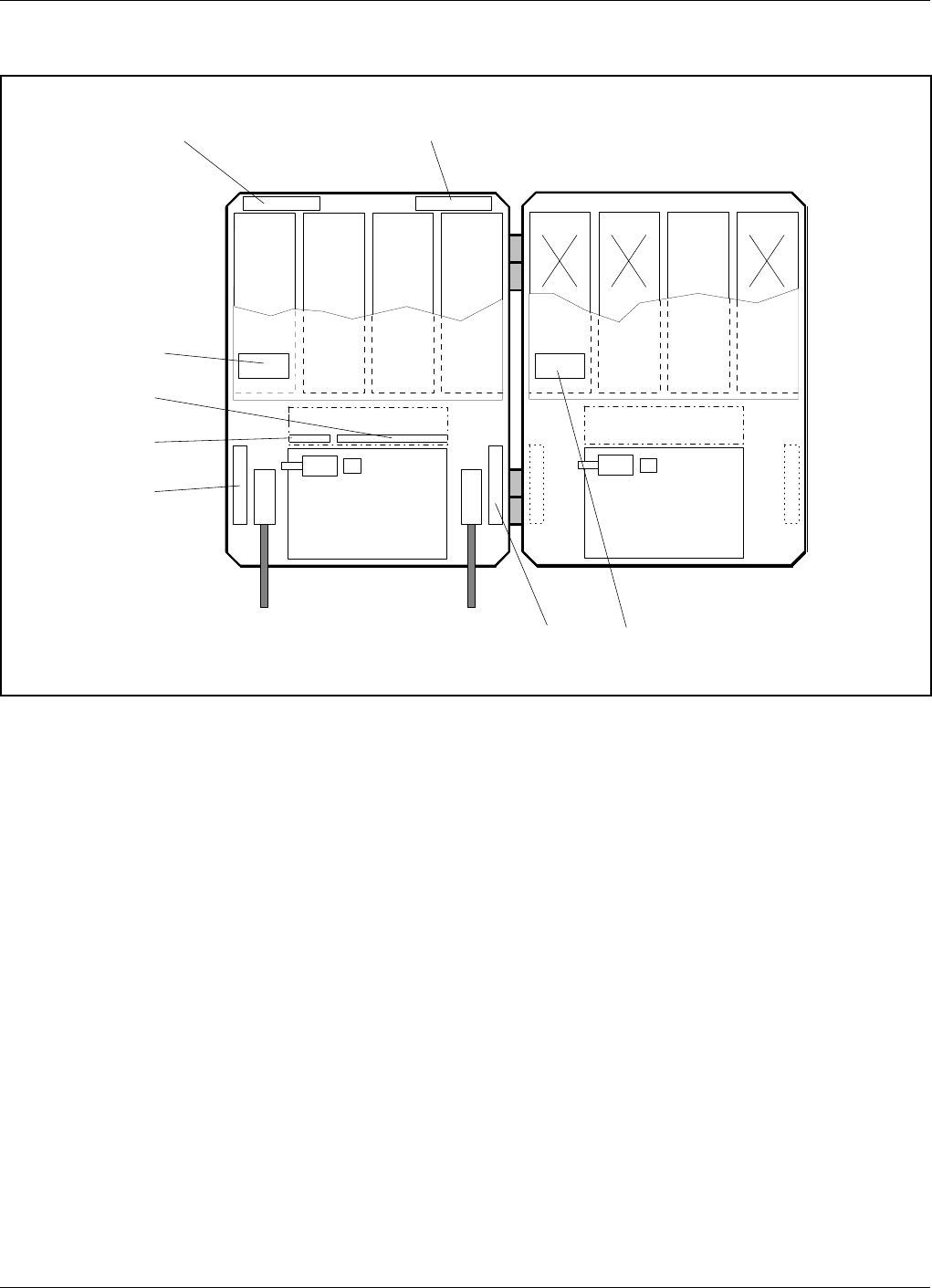
Channel Selective High Power CDMA Repeater
A cabinet (the left part in Figure 5-3) for a channel selective high power
CDMA repeater can be equipped with two pair of CSA and PA boards, one
pair for downlink (DL) and one pair for uplink (UL). The described
cabinet has a capacity of two bi-directional CDMA carriers.
The cover (the right part in Figure 5-3) is equipped with the BA board.
There is also a heat sink element on the outside of the cover, not shown
in Figure 5-3.
Note that this repeater type has opposed positions of the BS and MS
antenna inputs and DC units compared to all the other repeater types.
CSA boards are used for IS-95 or J-STD-008 types of CDMA systems.
Main units: ALI Alarm Interface board
BA Booster Amplifier board
CSA Channel Selective Amplifier board, CDMA type
CU Control Unit board
DC Directional Coupler
DPX Duplex filter
LNA Low Noise Amplifier
PA Power Amplifier board
PSU1,2 Power Supply Unit 1 and 2
123 4 567 8
CSA
DL
(2 carr.)
BS
Base station
antenna
MS
Mobile station
antenna
PA
DL CSA
UL
(2 carr.)
PA
UL
LNA DL
Downlink
LNA UL
Uplink
DPX
BS
DC
BS
CU
ALI
DC
MS DPX
MS
PSU1
BA
DL
PSU2
Figure 5-3. High power CDMA repeater
Functional Description AR Repeaters ALLGON System AB
5 - 6 Rev. P1A 2000-09 User’s Manual VD203 66/EN
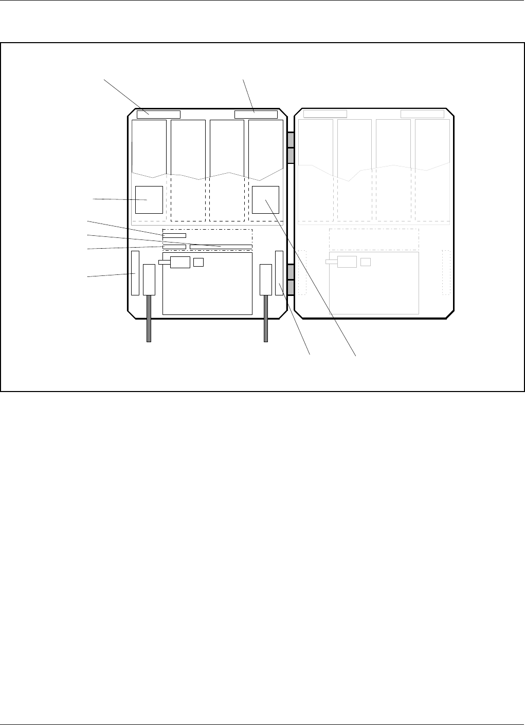
Band Selective Repeater
A cabinet (the left part in Figure 5-4) for a band selective repeater is
equipped with two pair of BSA and PA boards, one pair for downlink (DL)
and one pair for uplink (ULS). The described cabinet is equipped for
bi-directional band selective operation.
The cover (the right part in Figure 5-4) can be equipped as well. The
cover board positions are shown in the figure.
BSA boards are used for band selective systems either with a fixed band
width of 900MHz or an adjustable band width.
Main units: ALI Alarm Interface board
BSA Band Selective Amplifier board, fixed or adjustable band width
CU Control Unit board
DC Directional Coupler
DPX Duplex filter
LNA Low Noise Amplifier
PA Power Amplifier board
PSU Power Supply Unit
RIA Repeater to Repeater Interface Adapter (optional)
123 4 567 8
BSA
DL
MS
Mobile station
antenna
BS
Base station
antenna
PA
DL BSA
UL PA
UL
LNA DL
Downlink
LNA UL
Uplink
DPX
MS
DC
MS
CU
ALI
DC
BS DPX
BS
PSU
RIA
BSA
DL PA
DL BSA
UL PA
UL
Figure 5-4. Band selective repeater
ALLGON System AB AR Repeaters Functional Description
User’s Manual VD203 66/EN Rev. P1A 2000-09 5 - 7
Combined Repeater
Figure 5-5 shows an example of a combined channel selective and band
selective repeater. The channel selective part is located in the cabinet and
the band selective part in the cover.
This example has four bi-directional GSM channels and band selective
operation.
Any combinations of channel selective GSM part (page 5-4), channel
selective CDMA part (page 5-5) and band selective part (page 5-7) can be
mixed.
Main units: ALI Alarm Interface board
BSA Band Selective Amplifier board, fixed or adjustable band width
CHA Channel Selective Amplifier board, GSM type
CMB Combiner unit
CU Control Unit board
DC Directional Coupler
DPX Duplex filter
LNA Low Noise Amplifier
PA Power Amplifier board
PSU1,2 Power Supply Unit 1 and 2
RIA Repeater to Repeater Interface Adapter (optional)
123 4 567 8
CHA1
DL
(2 ch.)
MS
Mobile station
antenna
BS
Base station
antenna
CHA2
DL
(2 ch.)
CHA3
UL
(2 ch.)
CHA4
UL
(2 ch.)
LNA DL
Downlink
LNA UL
Uplink
CMB
Downlink
DPX
MS
DC
MS
CU
ALI
DC
BS CMB
Uplink DPX
BS
PSU1
BSA
DL PA
DL BSA
UL PA
UL
LNA UL
Uplink LNA DL
Downlink
PSU2
RIA
Figure 5-5. Combined repeater
Functional Description AR Repeaters ALLGON System AB
5 - 8 Rev. P1A 2000-09 User’s Manual VD203 66/EN

Block Diagram
The following block diagrams are found in this section:
•Channel selective GSM repeater, Figure 5-6 on page 5-10.
•Channel selective CDMA repeater, Figure 5-7 on page 5-12.
•Band selective repeater, Figure 5-8 on page 5-14.
The main signal paths for the repeater types are described under the
block diagrams.
Before the block diagrams are shown, the downlink and uplink signal
paths are described below.
Alarm is described on page 5-16.
Repeater setup is described on page 5-16.
Downlink Signal Path
The downlink signal path, i.e. from the base station through the repeater
to the mobile station, is described for channel selective GSM operation,
channel selective CDMA operation, and band selective operation under the
block diagrams on the following pages.
Uplink Signal Path
The uplink signal path, i.e. from the mobile station through the repeater
to the base station, is identical to the downlink path the other way round.
Only some levels and component values differ.
The high power CDMA repeater has, however, a booster amplifier in the
downlink path only.
ALLGON System AB AR Repeaters Functional Description
User’s Manual VD203 66/EN Rev. P1A 2000-09 5 - 9
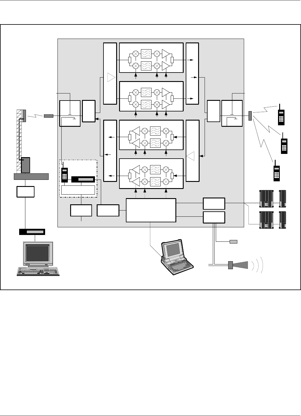
Channel Selective GSM Repeater
Figure 5-6 shows a block diagram of a channel selective repeater with four
bi-directional channels. This diagram is applicable to repeaters for the
GSM, DCS, PCN and GSM 1900 (PCS) systems.
Downlink signal path
The signal from the base station is received via the repeater BS antenna
and is then forwarded through a directional coupler (DC). The signal
passes a duplex filter (DPX), is amplified in a low noise amplifier (LNA),
and enters the channel boards (CHA), which have two parallel channels
each.
DC
BS
P31 P33
TEST -30 dB
DC
MS
TEST -30 dB
CHA1 - DL
CHA2 - DL
CHA3 - UL
CHA4 - UL
DPX
BS
LNA
DL CMB
DL
MS -20 dB
DPX
MS
ALI
RIA
CU
P34
ALLGON
ALLGON
ALL
ALL
RCU
P27 P32
PSU ALI
ANT OUT ANT HI
LO
HI
LO
IN
OUT1
OUT2
P101 P701
P101 P701
ANT OUT ANT
P101
P101
P701
P701
LNA
UL
IN
OUT1
OUT2
CMB
UL
MSC
CHANNEL
SELECTIVE
GSM
REPEATER
BS antenna
Base station
Telephone
line
Modem
Modem
Battery
External alarm sensors
MS antenna
R2R net
Figure 5-6. Block diagram, channel selective repeater
Functional Description AR Repeaters ALLGON System AB
5 - 10 Rev. P1A 2000-09 User’s Manual VD203 66/EN

The first mixer stage on the CHA amplifier board, which is controlled by
a synthesizer, converts the received frequency down to the IF frequency.
The signal is then filtered by SAW bandpass filters and, not shown in the
figure, amplified before it is fed to the second mixer stage for conversion
back to the original frequency.
The output signal from the mixer is then amplified in the power amplifier
and fed to a combiner, which combines the signals from the two channels
on the channel board.
The output signal passes a combiner (CMB), a duplex filter (DPX), and a
directional coupler (DC), before it is fed to the repeater MS antenna.
ALLGON System AB AR Repeaters Functional Description
User’s Manual VD203 66/EN Rev. P1A 2000-09 5 - 11
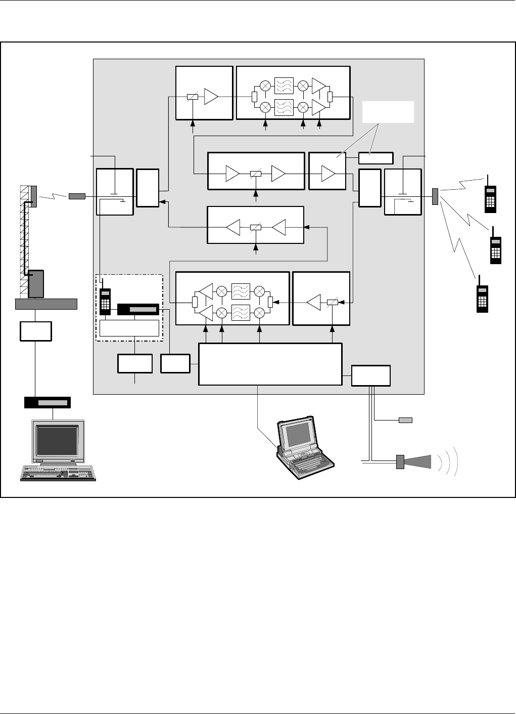
Channel Selective CDMA Repeater
Figure 5-7 shows a block diagram of a channel selective CDMA repeater.
This diagram is applicable only to repeaters for the CDMA system.
Downlink signal path
The signal from the base station is received via the repeater BS antenna
and is then forwarded through a directional coupler (DC). The signal
passes a duplex filter (DPX), is amplified in a low noise amplifier (LNA),
and enters the channel board (CSA), which has two parallel channels.
DC
BS
P32
P31 P33
TEST -30 dB
DC
MS
TEST -30 dB
PA - DL
LNA - DL
MS -20 dB PA - UL
LNA - UL
CSA - DL
DPX
MS
CSA - UL
ALI
CU
RCU
P27
ALI
PSU1
PSU2
DPX
BS
BA
ANT OUT HI
LO
ANT ANTOUT
ANT
HI
LO
IN OUT1 P101 P301
P4 P5 P3 P4
IN
OUT1
P101
P301
P4P5
MSC
CHANNEL
SELECTIVE
CDMA
REPEATER
BS antenna
Base station
Telephone
line
Modem
Modem
Battery
External alarm sensors
MS antenna
High power
CDMA only
Figure 5-7. Block diagram, CDMA repeater
Functional Description AR Repeaters ALLGON System AB
5 - 12 Rev. P1A 2000-09 User’s Manual VD203 66/EN

The first mixer stage on the CSA amplifier board, which is controlled by a
synthesizer, converts the received frequency down to the IF frequency.
The signal is then filtered by SAW bandpass filters and, not shown in the
figure, amplified before it is fed to the second mixer stage for conversion
back to the original frequency.
The following power amplifier is controlled by the CU. The output gain
can be reduced to avoid instability due to poor antenna isolation.
The output signal from the power amplifier is fed to a combiner, which
combines the signals from the two channels on the channel board.
A detector on the PA board measures continuously the output level. The
signal from this detector is used by the automatic gain control, AGC, to
supervise and, if necessary, reduce the output power to keep it under a
maximum level. The AGC gain control affects several of the amplification
stages.
BA in high power CDMA
repeaters only. In high power CDMA repeaters, a booster amplifier (BA) boosts the
output downlink signal by typically 6dB. The BA amplifier is powered by
a high power PSU2. Note that the booster amplifier (BA) is only present
in the downlink path, and only in high power CDMA repeaters.
The output signal passes a duplex filter (DPX) and a directional coupler
(DC) before it is fed to the repeater MS antenna.
ALLGON System AB AR Repeaters Functional Description
User’s Manual VD203 66/EN Rev. P1A 2000-09 5 - 13
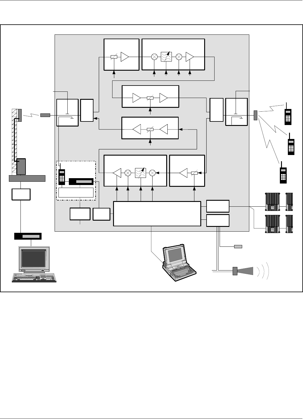
Band Selective Repeater
Figure 5-8 shows a block diagram of a band selective repeater. This
diagram is applicable to repeaters for e.g. NMT, TACS, ETACS, AMPS,
DAMPS and CDMA systems.
Downlink signal path
The signal from the base station is received via the repeater BS antenna
and is then forwarded through a directional coupler (DC). The signal
passes a duplex filter (DPX), is amplified in a low noise amplifier (LNA),
and enters the band selective amplifier board (BSA).
DC
BS
P32
P31 P33
TEST -30 dB
DC
MS
TEST -30 dB
BSA - DL
PA - DL
LNA - DL
MS -20 dB PA - UL
BSA - UL LNA - UL
DPX
MS
DPX
BS
ALI
RIA P34
CU
ALLGON
ALLGON
ALL
ALL
RCU
P27
PSU ALI
ANT OUT ANT HI
LO
ANTOUT
ANT
HI
LO
IN OUT1 P101 P301
P4 P5
IN
IN
OUT1
P301 P101
P4P5
MSC
BAND
SELECTIVE
REPEATER
BS antenna
Base station
Telephone
line
Modem
Modem
Battery
External alarm sensors
MS antenna
R2R net
Figure 5-8. Block diagram, band selective repeater
Functional Description AR Repeaters ALLGON System AB
5 - 14 Rev. P1A 2000-09 User’s Manual VD203 66/EN

The first mixer stage on the BSA amplifier board, which is controlled by a
synthesizer, converts the received frequency down to the IF frequency.
The signal is then filtered by SAW bandpass filters and, not shown in the
figure, amplified before it is fed to the second mixer stage for conversion
back to the original frequency.
The SAW filter can be either fixed or adjustable depending on the BSA
board used. If the BSA board has fixed band width, this SAW filter is
fixed and selected for the current band width. If the BSA board has
adjustable band width, the SAW filter combination can be software
changed from within OMT32 (or OMS) to cover various band widths.
The following power amplifier is controlled by the CU. The amplifier gain
will be reduced to avoid instability due to poor antenna isolation.
A detector on the PA board measures continuously the output level. The
signal from this detector is used by the automatic gain control, AGC, to
supervise and, if necessary, reduce the output power to keep it under a
maximum level. The AGC gain control affects several of the amplification
stages.
The output signal passes duplex filter (DPX) and a directional coupler
(DC) before it is fed to the repeater MS antenna.
RCU
The optional RCU Remote Communication Unit is located inside the
repeater (described in Chapter 6, Optionals).
Communication with the base station is performed by means of a built-in
mobile feature that has the antenna connected to the BS directional
coupler (DC). Data is transferred between the repeater and the built-in
RCU unit via the P32 modem port.
The RCU unit is powered via the P27 auxiliary port and the unit has a
battery with capacity to send a number of alarms if a mains power failure
occurs.
R2R
The Repeater to Repeater Link feature makes it possible to communicate
with a number of repeaters via one RCU unit in one of the repeaters in
an R2R net. Several RCU units can also be used in the same net.
The repeaters in the R2R net are connected to the P34 port.
The R2R feature is described in Chapter 6, Optionals.
ALLGON System AB AR Repeaters Functional Description
User’s Manual VD203 66/EN Rev. P1A 2000-09 5 - 15

Alarm
Alarm signals from external sensors are received by the ALI board, which
forwards the alarm signals to the CU board.
The software on the CU board is able to activate acoustic or visual alarm
or direct the alarm to the P33 alarm port to be forwarded, via the RCU
unit, to OMT32 (or OMS) located in an operation and maintenance
central.
Alarms can be configured from OMT32 (or from OMS).
Repeater Setup
The repeater parameters can be set locally by means of a desktop or
notebook loaded with the OMT32 software (or the OMS software). The
PC or notebook is connected to the CU via the P31 PC port (see
Figure 5-6, Figure 5-7 and Figure 5-8).
The repeater parameters can also be set remotely by means of a phone
(mobile or via a telephone line) and a modem connected to the CU board
via the P32 modem port (see Figure 5-6, Figure 5-7 and Figure 5-8).
Functional Description AR Repeaters ALLGON System AB
5 - 16 Rev. P1A 2000-09 User’s Manual VD203 66/EN
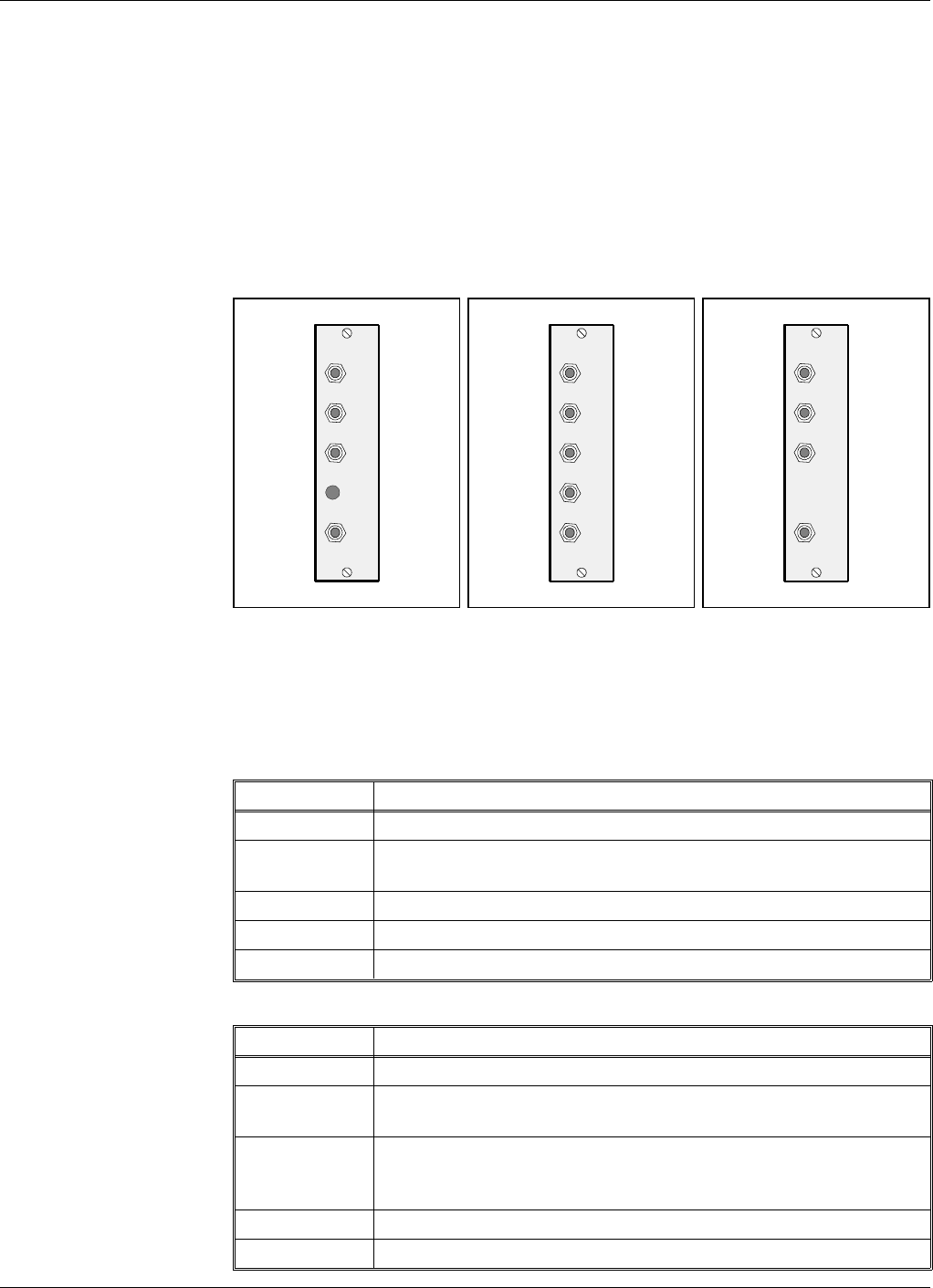
Board and Unit Descriptions
Cabling between boards and units is found on page 5-27.
DC - Directional Coupler
The BS and MS directional couplers, see Figure 5-9, are identical for all
repeaters except for the high power CDMA repeaters, which has BS and
MS directional couplers depiced in Figure 5-10 (BS) and Figure 5-11 (MS).
Connection
DC/MS:
Port Connected to
DPX ANT on the DPX/MS duplex filter.
TEST –30dB Test port for the downlink output signal. This port has
no directivity.
MS –20dB Not used.
MRX DC-BS on the MRX unit (high power CDMA only).
ANT MS antenna.
DC/BS:
Port Connected to
DPX ANT on the DPX/BS duplex filter.
TEST –30dB Test port for the uplink output signal. This port has no
directivity.
MS –20dB Mobile station antenna connection for remote control.
This port has at least 20dB directivity towards the
antenna.
MRX DC-MS on the MRX unit (high power CDMA only).
ANT BS antenna.
MS
DPX
ANT
TEST
DC
-30 dB
-20 dB
Figure 5-9. MS and
BS directional coupler
MRX
DPX
ANT
TEST
DC
-30 dB
MS
-20 dB
Figure 5-10. BS
directional coupler,
high power CDMA
MRX
DPX
ANT
TEST
DC
-30 dB
Figure 5-11. MS
directional coupler,
high power CDMA
ALLGON System AB AR Repeaters Functional Description
User’s Manual VD203 66/EN Rev. P1A 2000-09 5 - 17
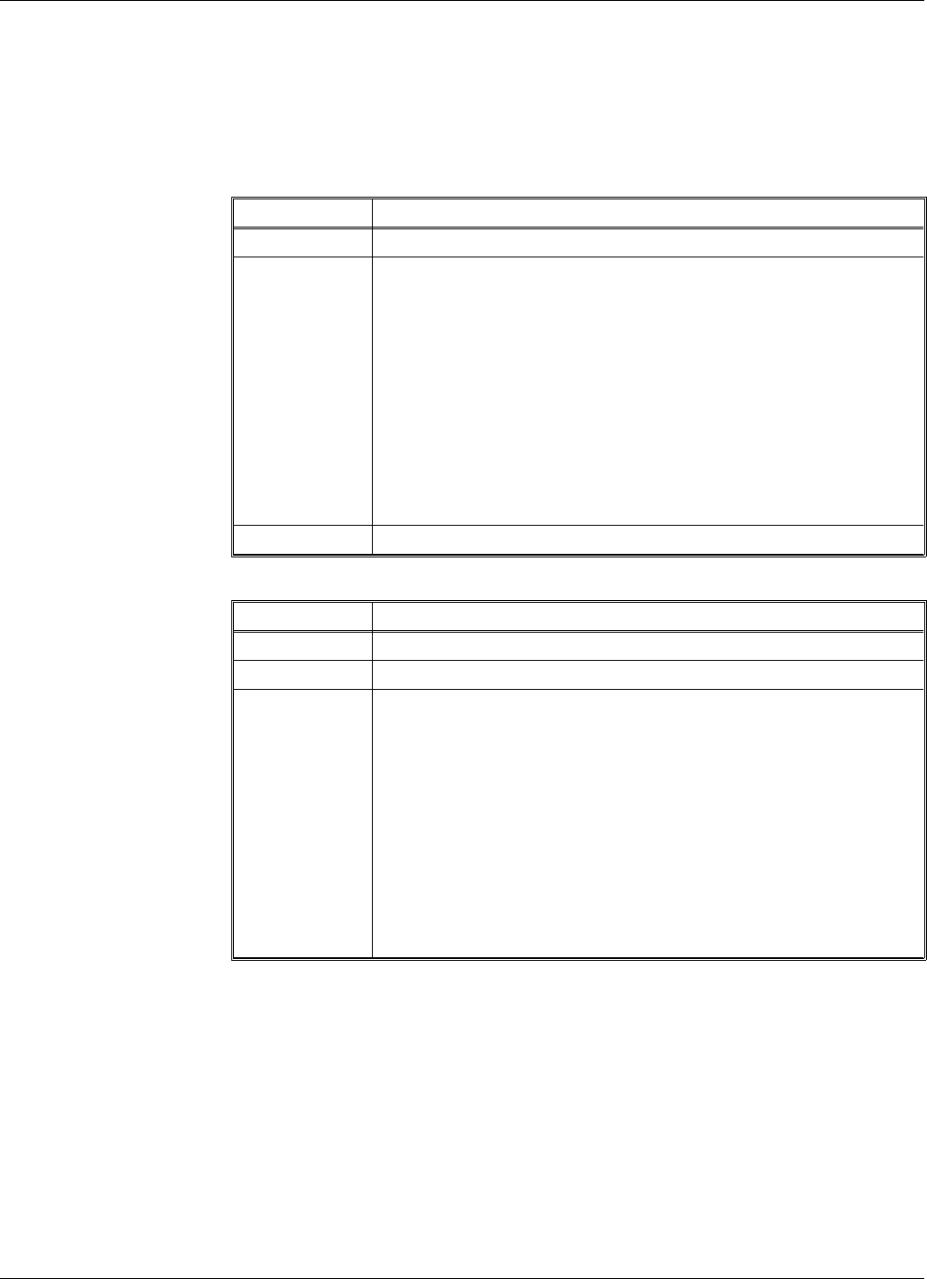
DPX - Duplex Filter
The DPX duplex filters on the BS and MS sides are identical.
Connection
DPX/MS:
Port Connected to
ANT DPX on the DC/MS directional coupler.
HI Channel selective GSM repeater:
Output on the CMB/DL combiner (at 4 channels),
P701 on the CHA1/DL channel board (at 2 channels).
Channel selective CDMA repeater:
P5 on the PA/DL board.
Channel selective high power CDMA repeater:
P4 on the BA board in the cover.
Band selective repeater:
P5 on the PA/DL board.
LO IN on the LNA/UL low noise amplifier.
DPX/BS:
Port Connected to
ANT DPX on the DC/BS directional coupler.
HI IN on the LNA/DL low noise amplifier.
LO Channel selective GSM repeater:
Output on the CMB/UL combiner (at 4 channels),
P701 on the CHA3/UL channel board (at 2 channels)
Channel selective CDMA repeater:
P5 on the PA/UL board.
Channel selective high power CDMA repeater:
P5 on the PA/UL board.
Band selective repeater:
P5 on the PA/UL board.
Functional Description AR Repeaters ALLGON System AB
5 - 18 Rev. P1A 2000-09 User’s Manual VD203 66/EN
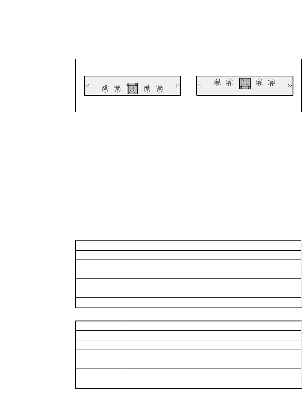
LNA - Low Noise Amplifier
The LNA low noise amplifiers are located in the outermost boxes at the
top of the cabinet and large cover (see Figure 5-1 to Figure 5-5 on
page 5-4 to 5-8). LNA/UL (uplink) is located to the left and LNA/DL
(downlink) to the right. All coaxial connectors are SMA type.
Signals from the duplex filter output is fed to the LNA input connector
IN. Output OUT1 and OUT2 feed the CHA boards of the same signal
direction. The signal level in these connectors are +20dB referred to the
antenna input. Another output, OUT LOW, is an expansion output for an
additional LNA amplifier, if the repeater is equipped in the cover part of
the chassis. The gain to this connector is +2dB.
The +7V input is used for 7V supply from the DIA board.
ATT is a control signal for a controllable attenuator in the LNA.
Connection
To the left in the cabinet LNA/UL:
Port Connected to
OUT LOW IN on the LNA/UL in the cover if equipped.
IN LO on the DPX/MS duplex filter.
ATT P23 on the DIA board.
+7V P23 on the DIA board.
OUT1 P101 on the CHA3/UL or CSA/UL or BSA/UL board.
OUT2 P101 on the CHA4/UL channel board.
To the right in the cabinet LNA/DL:
Port Connected to
OUT LOW IN on the LNA/DL in the cover if equipped.
IN HI on the DPX/BS duplex filter.
ATT P24 on the DIA board.
+7V P24 on the DIA board.
OUT1 P101 on the CHA1/DL or CSA/DL, or BSA/DL board.
OUT2 P101 on the CHA2/DL channel board.
Not used outputs do not need to be terminated.
OUT
LOW
IN+7V ATTOUT1 OUT2
LNA
DL
OUT
LOW IN ATT +7V OUT1 OUT2
LNA
UL
Figure 5-12. LNA low noise amplifier
ALLGON System AB AR Repeaters Functional Description
User’s Manual VD203 66/EN Rev. P1A 2000-09 5 - 19
CHA - Channel Amplifier Board for Channel Selective Operation
The cabinet can be equipped with four CHA Channel Amplifier boards.
These are numbered from left to right: CHA1 - CHA4. The board
positions CHA1 - CHA2 are used for downlink and CHA3 - CHA4 for
uplink (see Figure 5-1 on page 5-4). If the repeater is equipped with two
channels only, the board positions 1 and 3 are used.
The two internal channels on each CHA board are located to the left and
to the right on the board.
If a board is to be removed, the RFI filter at the board connector and the
two coaxial connectors must be removed prior to the board removal. No
heat compound is used on the heat sink body or on the chassis.
Coaxial connector P101 is the input of the CHA board fed from the LNA.
Coaxial connector P701 is the output of the board. The output signal is
fed to the duplex filter, either directly or via a CMB combiner, depending
on the repeater configuration.
Connection
Board #1 from left CHA1/DL:
Port Connected to
P101 OUT1 on the LNA/DL low noise amplifier.
P701 4 channels: Input on the CMB/DL combiner.
2 channels: HI on the DPX/MS duplex filter.
Board #2 from left CHA2/DL:
Port Connected to
P101 OUT2 on the LNA/DL low noise amplifier.
P701 Input on the CMB/DL combiner.
Board #3 from left CHA3/DL:
Port Connected to
P101 OUT1 on the LNA/UL low noise amplifier.
P701 4 channels: Input on the CMB/UL combiner.
2 channels: LO on the DPX/BS duplex filter.
Board #4 from left CHA4/DL:
Port Connected to
P101 OUT2 on the LNA/UL low noise amplifier.
P701 Input on the CMB/UL combiner.
Caution
BERYLLIUM OXIDE
The CHA Channel Amplifier board power transistors contain beryllium
oxide (BeO) that is poisonous. The power transistors are mounted with
two screws as opposed to other transistors. See Chapter 1, Safety.
Functional Description AR Repeaters ALLGON System AB
5 - 20 Rev. P1A 2000-09 User’s Manual VD203 66/EN
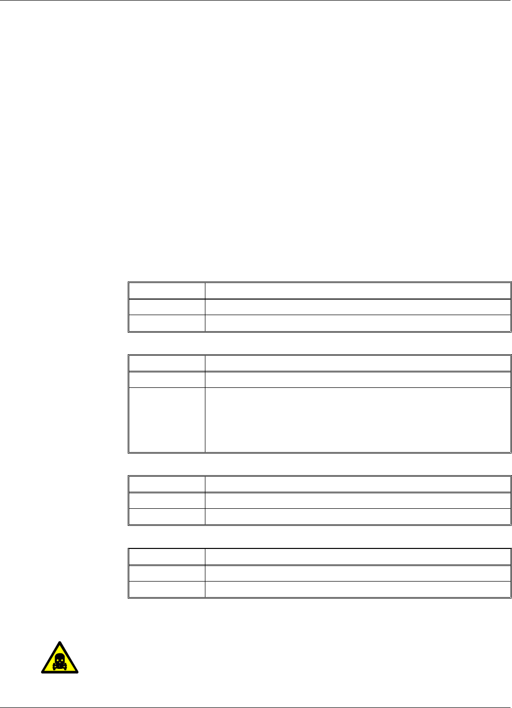
CSA and PA Boards for Channel Selective CDMA Operation
For channel selective CDMA operation, the cabinet is normally equipped
with two CSA and two PA boards. These are numbered from left to right.
Board position 1 is used for CSA downlink board, position 2 for PA
downlink board, position 3 for CSA uplink board, and position 4 for PA
uplink board (see Figure 5-2 on page 5-5).
If a board is to be removed, the RFI filter at the board connector, the two
coaxial connectors, and the flat conductor cable between the CSA board
and the PA board must be removed prior to the board removal. No heat
compound is used on the heat sink body or on the chassis.
Coaxial connector P101 is the input of the CSA board fed from the LNA.
Coaxial connector P301 is the output of the CSA board. The signal from
this output is fed to the PA board input P4. The PA board output P5 is
fed to the duplex filter of the same signal direction.
Connection
Board #1 from left CSA/DL:
Port Connected to
P101 OUT1 on the LNA/DL low noise amplifier.
P301 P4 on the PA/DL board.
Board #2 from left PA/DL:
Port Connected to
P4 P301 on the CSA/DL board.
P5 Channel selective high power CDMA repeater:
P3 on the BA board in the cover.
All other repeater types:
HI on the DPX/MS duplex filter.
Board #3 from left CSA/UL:
Port Connected to
P101 OUT1 on the LNA/UL low noise amplifier.
P301 P4 on the PA/UL board.
Board #4 from left PA/UL:
Port Connected to
P4 P301 on the CSA/UL board.
P5 LO on the DPX/BS duplex filter.
Caution
BERYLLIUM OXIDE
The PA Power Amplifier board power transistors contain beryllium oxide
(BeO) that is poisonous. The power transistors are mounted with two
screws as opposed to other transistors. See Chapter 1, Safety.
ALLGON System AB AR Repeaters Functional Description
User’s Manual VD203 66/EN Rev. P1A 2000-09 5 - 21
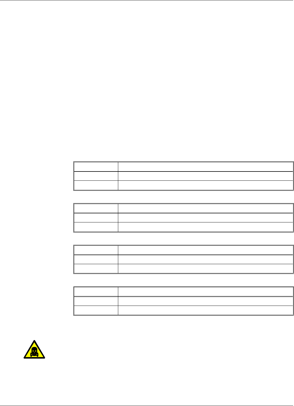
BSA and PA Boards for Band Selective Operation
For band selective operation, the cabinet is equipped with two BSA and
two PA boards. These are numbered from left to right. Board position 1
is used for BSA downlink board, position 2 for PA downlink board,
position 3 for BSA uplink board, and position 4 for PA downlink board
(see Figure 5-4 on page 5-7).
If a board is to be removed, the RFI filter at the board connector, the two
coaxial connectors, and the flat conductor cable between the BSA board
and the PA board must be removed prior to the board removal. No heat
compound is used on the heat sink body or on the chassis.
Coaxial connector P101 is the input of the BSA board fed from the LNA.
Coaxial connector P301 is the output of the BSA board. The signal from
this output is fed to the PA board input P4. The PA board output P5 is
fed to the duplex filter of the same signal direction.
Connection
Board #1 from left BSA/DL:
Port Connected to
P101 OUT1 on the LNA/DL low noise amplifier.
P301 P4 on the PA/DL board.
Board #2 from left PA/DL:
Port Connected to
P4 P301 on the BSA/DL board.
P5 HI on the DPX/MS duplex filter.
Board #3 from left BSA/UL:
Port Connected to
P101 OUT1 on the LNA/UL low noise amplifier.
P301 P4 on the PA/UL board.
Board #4 from left PA/UL:
Port Connected to
P4 P301 on the BSA/UL board.
P5 LO on the DPX/BS duplex filter.
Caution
BERYLLIUM OXIDE
The PA Power Amplifier board power transistors contain beryllium oxide
(BeO) that is poisonous. The power transistors are mounted with two
screws as opposed to other transistors. See Chapter 1, Safety.
Functional Description AR Repeaters ALLGON System AB
5 - 22 Rev. P1A 2000-09 User’s Manual VD203 66/EN
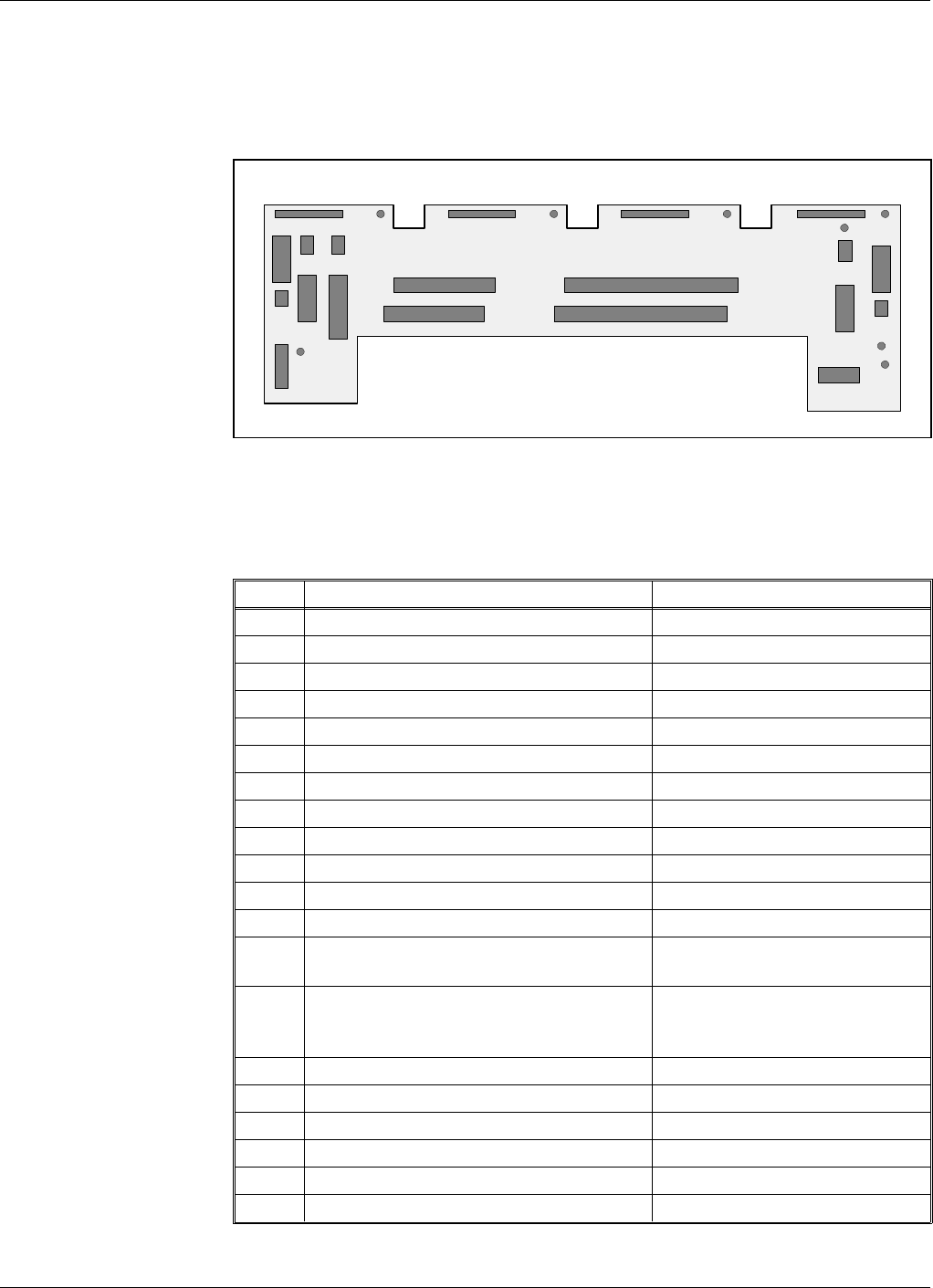
DIA Board
DIA is a distribution board for most of the boards, units and ports. The
DIA board is exclusively equipped with connectors. The connector types
are chosen to prevent unintentional mixing up.
Connection and connector types
Port Connected to Connector type
P2 CU board
P3 Not used
P4 ALI board
P5 Not used
P11 CHA1/DL or CSA/DL or BSA/DL 16 pole 1 line female
P12 CHA2/DL or PA/DL 16 pole 1 line female
P13 CHA3/UL or CSA/UL or BSA/UL 16 pole 1 line female
P14 CHA4/UL or PA/UL 16 pole 1 line female
P21 PSU - Power Supply Unit 10 pole 2 line male
P22 LED board in the cover 4 pole 1 line male
P23 LNA/UL 2 pole 1 line male
P24 LNA/DL 2 pole 1 line male
P25 Expansion output port to cover
circuitry if any. Only in cabinets. 16 pole 2 line male
P26 Expansion input port from the
cabinet. Used in equipped large
covers only.
16 pole 2 line male
*P27 AUX1 auxiliary connector 8 pole 1 line male
P28 Door switch (internal alarm) 3 pole 1 line male
P31 PC (serial RS-232) 9 pole D-sub female
P32 Modem (serial RS-232) 9 pole D-sub male
P33 External alarm 15 pole D-sub female
P34 Repeater to Repeater Link 8 pole RJ45 modular female
*Pin 2 and 3 on the P27 connector must be interconnected with a jumper
if the connector is not used.
P28
P33
P26
P32
P23
P27
P5 P3
P4 P2
P11 P12 P13 P14
P21
P31
P22 P25
P24
U7A U7B U7C U26
U7D
U7E
U7F
GND
P34
Figure 5-13. DIA board connectors and testpoints
ALLGON System AB AR Repeaters Functional Description
User’s Manual VD203 66/EN Rev. P1A 2000-09 5 - 23

Testpoints
Testpoint Voltage Purpose
U7A +7V DC CHA1/DL or CSA/DL or BSA/DL downlink
board supply voltage.
U7B +7V DC CHA2/DL or PA/DL downlink board supply
voltage.
U7C +7V DC CHA3/UL or CSA/UL or BSA/UL downlink
board supply voltage.
U7D +7V DC CHA4/UL or PA/UL downlink board supply
voltage.
U7E +7V DC LNA/UL and LNA/DL and P27 auxiliary port
supply voltage.
U7F +7V DC CU board and ALI board and RCU supply
voltage via the P27 auxiliary port jumper.
U26 +26V DC
or
+13V DC
or
+10V DC
Power amplifiers and P27 auxiliary port supply
voltage (26V, 13V or 10V depending on the
repeater type).
GND 0 Ground
DIA board part # and version
The DIA board part # is K105/1. Version R2A or higher (containing the
P34 connector) is required to use the optional Repeater to Repeater Link
feature.
Functional Description AR Repeaters ALLGON System AB
5 - 24 Rev. P1A 2000-09 User’s Manual VD203 66/EN

CU Control Unit Board
The CU board is the central board in the repeater, located in the repeater
cabinet. The CU board contains a microprocessor, main memory, flash
memory for the CU software, EEPROM memory for parameters, memory
for the event log and statistics, a REFO reference oscillator, ports for local
and remote communication, battery powered real-time clock, etc.
The CU board is used to supervise and control operational parameters
such as gain control, channel handling, etc. The CU takes care of alarms
and the event log, password and logon, and many other procedures.
The CU is also a control interface when using an OMT32/PC or OMS/PC,
locally or remotely via modem.
The CU software can be downloaded from an OMT32/PC or OMS/PC,
either locally or remotely.
The real-time clock on the CU board is used for alarm and for the event
log.
There are currently two CU board variants: K103/1 and K103/2.
CU board and CU software part #s
K103/1 CU board (old)
CU board K103/1 can be run with the SA102 01/2 CU software. This
board can store one version of CU software. The repeater will always
boot on this software version.
K103/2 CU board (current) CU board K103/2 can be run with either the old SA102 01/2 CU software
or the current SA102 02/1 or SA102 02/2 CU software. This board can
store two versions of CU software, located in segment 1 and segment 2 of
the flash memory as Application 1 and Application 2. The repeater will
boot on that software which is set as Primary (description of Primary
application is found in the OMT32, User’s Manual).
Compatibility for CU boards and CU software is detailed in the next
section.
Connection
The CU board is connected to the DIA board via the P2 port.
Caution
A lithium battery is permanently mounted on the CU board. Due to the
risk of explosion, this battery must not be removed from the board. In
case of battery malfunction, replace the CU board. The old CU board can
be sent to Allgon for repair.
ALLGON System AB AR Repeaters Functional Description
User’s Manual VD203 66/EN Rev. P1A 2000-09 5 - 25

Repeater CU Software and Hardware Compatibility
There are different versions of repeater CU software, which can be
combined with boards of various revisions. These have unique part
numbers and revision information. Below, you will find a table of
repeater software currently available in combination with CU board
revisions.
CU Software
Part # Latest
Software
Revision
Compatible
with
CU board
Comments
SA102 01/2 R2E K103/1
or
K103/2
For GSM channel selective
≤ 4 channels, band selective
800-900MHz fixed band
width only, and combi
(800/900MHz).
No traffic statistics.
SA102 02/1 R3A K103/2 For GSM, EGSM, DCS,
PCS channel selective
≤ 8 channels, band selective
800-900MHz fixed or
adjustable band width,
band selective 1800MHz or
1900MHz and combi.
Supports R2R link.
SA102 02/2 R2A K103/2 For 800/1900MHz CDMA
≤ 4 channels.
This information is updated 2000-10-01. As new versions of hardware
and software are released without prior noticing, contact your Allgon sales
representative if in doubt about the latest revision status.
For detailed information, refer to the release notes for the CU software to
be downloaded (normally found in the readme.txt file, which is supplied
with the program files).
Functional Description AR Repeaters ALLGON System AB
5 - 26 Rev. P1A 2000-09 User’s Manual VD203 66/EN

Cabling
On the following pages, you will find cabling information for the various
repeater types:
•Channel selective GSM repeater, 2 channels (page 5-28).
•Channel selective GSM repeater, 4 channels (page 5-29).
•Channel selective CDMA repeater (page 5-30).
•Channel selective high power CDMA repeater (page 5-31).
•Band selective repeater (page 5-32).
ALLGON System AB AR Repeaters Functional Description
User’s Manual VD203 66/EN Rev. P1A 2000-09 5 - 27
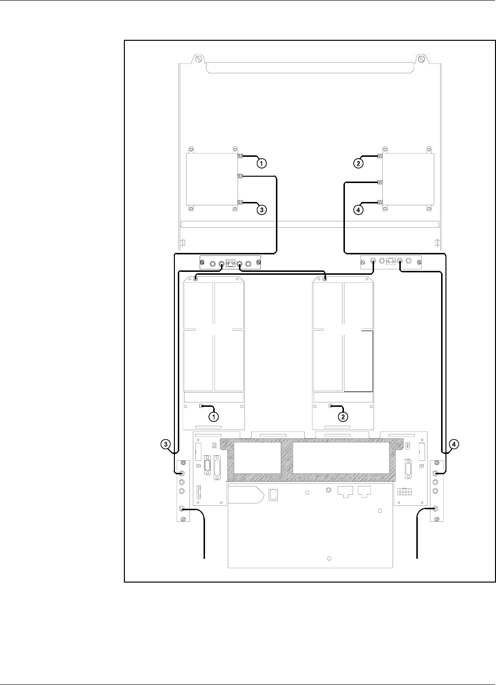
Channel Selective GSM Repeater, 2 Channels
Figure 5-14 shows a repeater equipped with the two channel boards
CHA1/DL and CHA3/UL for two bi-directional GSM channels.
DOOR
P28
1
3
1
P26
P23
LNA
UL
1
2
16
1
8
AUX1
P25
16
1
P24
DL
LNA
1
2
P31
PC
P22
LED
P21
PSU
1
10
116 161 161 116
1
0
LNA
UL
ATT +7V OUT1 OUT2
LOW
OUT IN
DC
OUT
TEST 1
MS
ANT
IN/OUT
MS P32 P33
MODEM
EXT LARM
BS
DC
OUT
TEST 1
MS
ANT
IN/OUT
LNA
DL OUT1 OUT2 +7V ATT IN OUT
LOW
DPX
MS DPX
BS
HI
ANT
LO HI
ANT
LO
P101 P101
P701 P701
LNA
UL
ATT +7V OUT1 OUT2
LOW
OUT IN
116 116
CHA1/DL CHA3/UL
BS
MS
Power Supply Unit
Figure 5-14. Cabling, GSM repeater - 2 ch.
Functional Description AR Repeaters ALLGON System AB
5 - 28 Rev. P1A 2000-09 User’s Manual VD203 66/EN
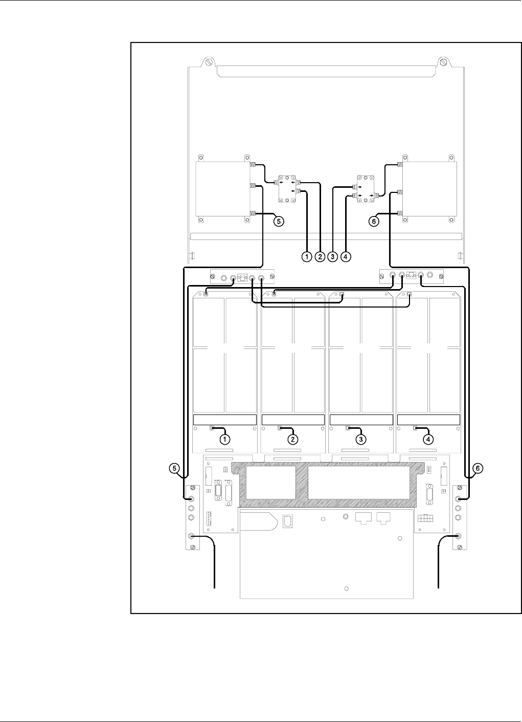
Channel Selective GSM Repeater, 4 Channels
Figure 5-15 shows a channel selective repeater equipped with the channel
boards CHA1/DL, CHA2/DL, CHA3/UL, and CHA4/UL for four
bi-directional GSM channels.
DOOR
P28
1
3
1
P26
P23
LNA
UL
1
2
16
1
8
AUX1
P25
16
1
P24
DL
LNA
1
2
P31
PC
P22
LED
P21
PSU
1
10
116 161 161 116
1
0
LNA
UL
ATT +7V OUT1 OUT2
LOW
OUT IN
DC
OUT
TEST 1
MS
ANT
IN/OUT
MS P32 P33
MODEM
EXT LARM
BS
DC
OUT
TEST 1
MS
ANT
IN/OUT
LNA
DL OUT1 OUT2 +7V ATT IN OUT
LOW
DPX
MS DPX
BS
HI
ANT
LO HI
ANT
LO
CMB
DL
CMB
UL
P101 P101 P101 P101
P701 P701 P701 P701
116116116116
CHA1/DL CHA2/DL CHA3/UL CHA4/UL
BSMS
Power Supply Unit
Figure 5-15. Cabling, GSM repeater - 4 ch.
ALLGON System AB AR Repeaters Functional Description
User’s Manual VD203 66/EN Rev. P1A 2000-09 5 - 29
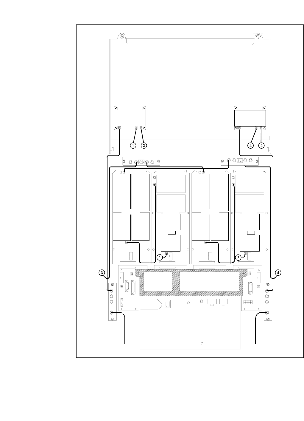
Channel Selective CDMA Repeater
Figure 5-16 shows a channel selective CDMA repeater equipped with two
CSA boards and two PA boards.
DOOR
P28
1
3
1
P26
P23
LNA
UL
1
2
16
1
8
AUX1
P25
16
1
P24
DL
LNA
1
2
P31
PC
P22
LED
P21
PSU
1
10
116 161 161 116
1
0
LNA
UL
ATT +7V OUT1 OUT2
LOW
OUT IN
DC
OUT
TEST 1
MS
ANT
IN/OUT
MS P32 P33
MODEM
EXT LARM
BS
DC
OUT
TEST 1
MS
ANT
IN/OUT
LNA
DL OUT1 OUT2 +7V ATT IN OUT
LOW
1
1
16
2
9
10
P301
P101
1
1
16
2
9
10
P5
P4
1
1
16
2
9
10
P301
P101
1
1
16
2
9
10
P5
P4
DPX
MS
LO
ANT HI
DPX
BS
LO
ANT HI
CSA/DL PA/DL CSA/UL PA/UL
BSMS
Power Supply Unit
Figure 5-16. Cabling, CDMA repeater - 2 ch.
Functional Description AR Repeaters ALLGON System AB
5 - 30 Rev. P1A 2000-09 User’s Manual VD203 66/EN
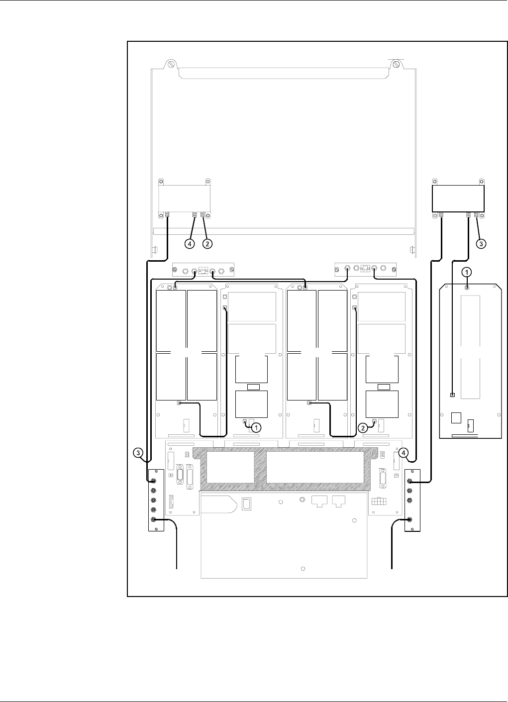
Channel Selective High Power CDMA Repeater
Figure 5-17 shows a channel selective high power CDMA repeater
equipped with two CSA boards, two PA boards and a BA board (in the
cover).
DOOR
P28
1
3
1
P26
P23
LNA
UL
1
2
16
1
8
AUX1
P25
16
1
P24
DL
LNA
1
2
P31
PC
P22
LED
P21
PSU
1
10
116 161 161 116
1
0
LNA
UL
ATT +7V OUT1 OUT2
LOW
OUT IN
DC
OUT
TEST 1
MS
ANT
IN/OUT
MS P32 P33
MODEM
EXT LARM
BS
DC
OUT
TEST 1
MS
ANT
IN/OUT
LNA
DL OUT1 OUT2 +7V ATT IN OUT
LOW
MRX
DPX
ANT
TEST
DC
-30 dB
MS
-20 dB
MRX
DPX
ANT
TEST
DC
-30 dB
BS
1
1
16
2
9
10
P301
P101
1
1
16
2
9
10
P5
P4
1
1
16
2
9
10
P301
P101
1
1
16
2
9
10
P5
P4
DPX
BS
LO
ANT HI
DPX
BS
LO
ANT HI
CSA/DL PA/DL CSA/UL PA/UL
BS MS
MS
1
1
16
2
9
10
P4
P3
BA/DL
Power Supply Unit
Figure 5-17. Cabling, high power CDMA repeater - 2 ch.
ALLGON System AB AR Repeaters Functional Description
User’s Manual VD203 66/EN Rev. P1A 2000-09 5 - 31
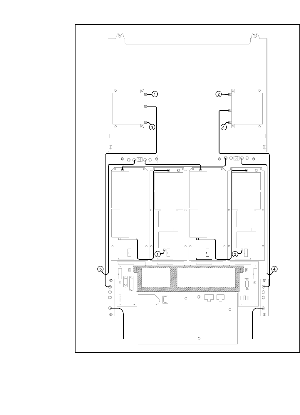
Band Selective Repeater
Figure 5-18 shows a band selective repeater equipped with two BSA
boards and two PA boards.
DOOR
P28
1
3
1
P26
P23
LNA
UL
1
2
16
1
8
AUX1
P25
16
1
P24
DL
LNA
1
2
P31
PC
P22
LED
P21
PSU
1
10
116 161 161 116
1
0
LNA
UL
ATT +7V OUT1 OUT2
LOW
OUT IN
DC
OUT
TEST 1
MS
ANT
IN/OUT
MS P32 P33
MODEM
EXT LARM
BS
DC
OUT
TEST 1
MS
ANT
IN/OUT
LNA
DL OUT1 OUT2 +7V ATT IN OUT
LOW
DPX
MS DPX
BS
HI
ANT
LO HI
ANT
LO
1
1
16
2
9
10
P301
P101
1
1
16
2
9
10
P5
P4
1
1
16
2
9
10
P301
P101
1
1
16
2
9
10
P5
P4
BSA/DL PA/DL BSA/UL PA/UL
BSMS
Power Supply Unit
Figure 5-18. Cabling, band selective repeater
Functional Description AR Repeaters ALLGON System AB
5 - 32 Rev. P1A 2000-09 User’s Manual VD203 66/EN

6. Optionals
This chapter describes the following optional accessories available for the
Allgon repeaters:
•RCU, Remote Control Unit for GSM 900, page 6-2.
•RCU, Remote Control Unit with PCMCIA Modem, page 6-4.
•OMS, Operation and Maintenance System, page 6-8.
•Traffic Statistics, page 6-8.
•Battery Backup, page 6-8.
•Fiber Optic Interface, page 6-8.
•7/16" Antenna Cable Connectors, page 6-8.
•R2R, Repeater To Repeater Link, page 6-9.
Allgon Systems AB AR Repeaters Optionals
User’s Manual VD203 66/EN Rev. P1A 2000-09 6 - 1
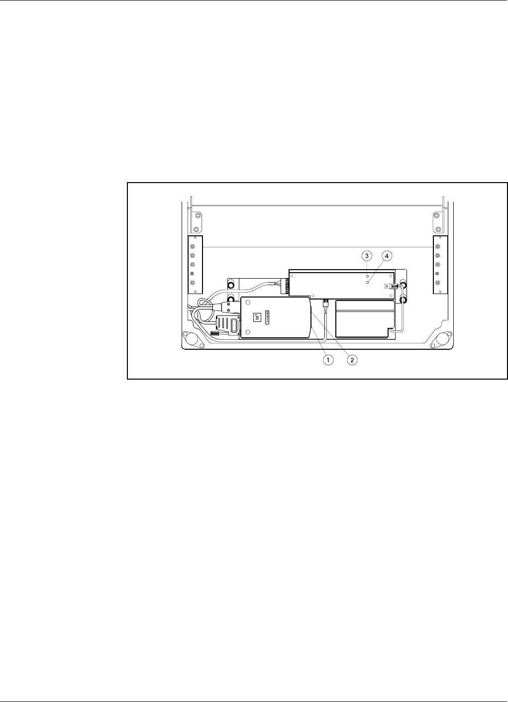
RCU, Remote Control Unit for GSM 900
As the mobile phone technology is developing very fast, this RCU may be
modified after issuing this manual. New types may also have been added.
For the latest details, please contact your local Allgon representative.
For remote control of Allgon repeaters in the GSM 900 system an RCU
Remote Control Unit is available as a kit. This kit contains an integrated
mobile phone/modem, power supply and power supply backup. A detailed
installation guide is also included in the RCU kit.
The RCU for the GSM system is mounted inside the repeater cabinet, in
front of the PSU (see Figure 6-1).
The RCU is connected to the P27, P32, and MS -20dB ports as described
in the Connection section in Chapter 3.
12volt 0.7Ah
MS
DPX
ANT
TEST
DC
-30 dB
-20 dB
MS
DPX
ANT
TEST
DC
-30 dB
-20 dB
Figure 6-1. RCU - GSM 900 type
Optionals AR Repeaters Allgon Systems AB
6 - 2 Rev. P1A 2000-09 User’s Manual VD203 66/EN

RCU kit items
The item numbers refer to the numbers in Figure 6-1.
1. The GSM board. Press a pencil or similar object on the small button
adjacent to the SIM board to release it.
2. LED indicator on the M1 phone/modem unit which shows three
operational modes:
Out: The unit is off
Slow flashing: Stand by
Fast flashing: Connection in progress
3. Green LED on the battery charger which is lit with a steady light
when the power supply is OK, either from the mains or from the
battery.
4. Yellow LED on the battery charger which is lit with a steady light
during battery charge from the mains.
Do not forget to put a jumper between pin 2 and 3 on the P27 connector if
you disconnect the RCU.
GSM subscriber conditions
•Data transmission, 9600 bps (baud)
•Transparent mode
•If the PIN code have to be disabled, use another phone.
If you get problems with the PIN code, please contact Allgon Technical
Support.
Power supply backup
If a power failure occurs, the backup battery has capacity to supply the
CU, ALI and phone/modem for 30 minutes at room temperature and a
limited number of call attempts.
The battery life is 1 - 2 years at normal indoor temperature. If the
operational temperature is higher, the battery life is shortened.
Power supply battery type
12V, 0.7A/20h, lead, sealed, including cable and JST VHR-2N connector.
Part # Allgon: PM291 09/1
Hitachi: HP0.7-12P (VHR-2N)
Yuasa: NP0.8-12
Allgon Systems AB AR Repeaters Optionals
User’s Manual VD203 66/EN Rev. P1A 2000-09 6 - 3

RCU, Remote Control Unit with PCMCIA Modem
As the mobile phone technology is developing very fast, this RCU may be
modified after issuing this manual. New types may also have been added.
For the latest details, please contact your local Allgon representative.
For remote control of Allgon repeaters in various systems, two PCMCIA
modem based RCU Remote Control Units are available as kits.
These are:
•RCU Kit for PCMCIA - Fixed Wire Line Connection
•RCU Kit for PCMCIA - Wireless Connection
These RCUs are basically two similars, but the Fixed Wire Line
Connection kit does not include accessories for a mobile phone.
Detailed installation guides are included in the RCU kits.
RCU Kit for PCMCIA - Fixed Wire Line Connection
This kit contains a PCMCIA card host, power supply, and power supply
backup.
Most Hayes compatible PCMCIA card modems (not included in the kit)
can be used.
RCU Kit for PCMCIA - Wireless Connection
This kit contains a PCMCIA card host, power supply, power supply
backup, mobile phone bracket, battery charger, charging cable, and mobile
phone antenna cable.
The following mobile phones have been tested together with a DC23 type
modem and are thus recommended by Allgon:
–Ericsson PH388 in DCS/PCN 1800MHz system
–Ericsson GH388 in GSM 1900MHz system
Power supply backup
If a power failure occurs, the included backup battery has capacity to
supply the CU, ALI and the modem. For the Wireless Connection type,
this is applicable provided the specified configuration of mobile phone and
PCMCIA modem is used.
The battery life is 1 - 2 years at normal indoor temperature. If the
operational temperature is higher, the battery life is shortened.
Optionals AR Repeaters Allgon Systems AB
6 - 4 Rev. P1A 2000-09 User’s Manual VD203 66/EN
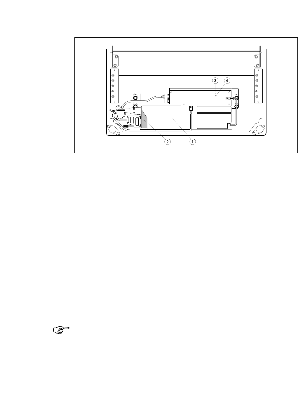
RCU for Fixed Wire Line Connection
The RCU for Fixed Wire Line Connection is mounted inside the repeater
cabinet, in front of the PSU (see Figure 6-2).
The RCU is connected to the P27 and P32 ports as described in the
Connection section in Chapter 3.
A free strain relief bushing at the bottom of the repeater is used for the
external telephone line cable.
RCU kit items - Fixed Wire Line Connection
The item numbers refer to the numbers in Figure 6-2.
1. PCMCIA modem card host.
2. PCMCIA modem card (not included in the kit).
3. Green LED on the battery charger which is lit with a steady light
when the power supply is OK, either from the mains or from the
battery.
4. Yellow LED on the battery charger which is lit with a steady light
during battery charge from the mains.
Do not forget to put a jumper between pin 2 and 3 on the P27 connector if
you disconnect the RCU.
12volt 0.7Ah
MS
DPX
ANT
TEST
DC
-30 dB
-20 dB
MS
DPX
ANT
TEST
DC
-30 dB
-20 dB
Figure 6-2. RCU - Fixed Wire Line PCMCIA type
Allgon Systems AB AR Repeaters Optionals
User’s Manual VD203 66/EN Rev. P1A 2000-09 6 - 5
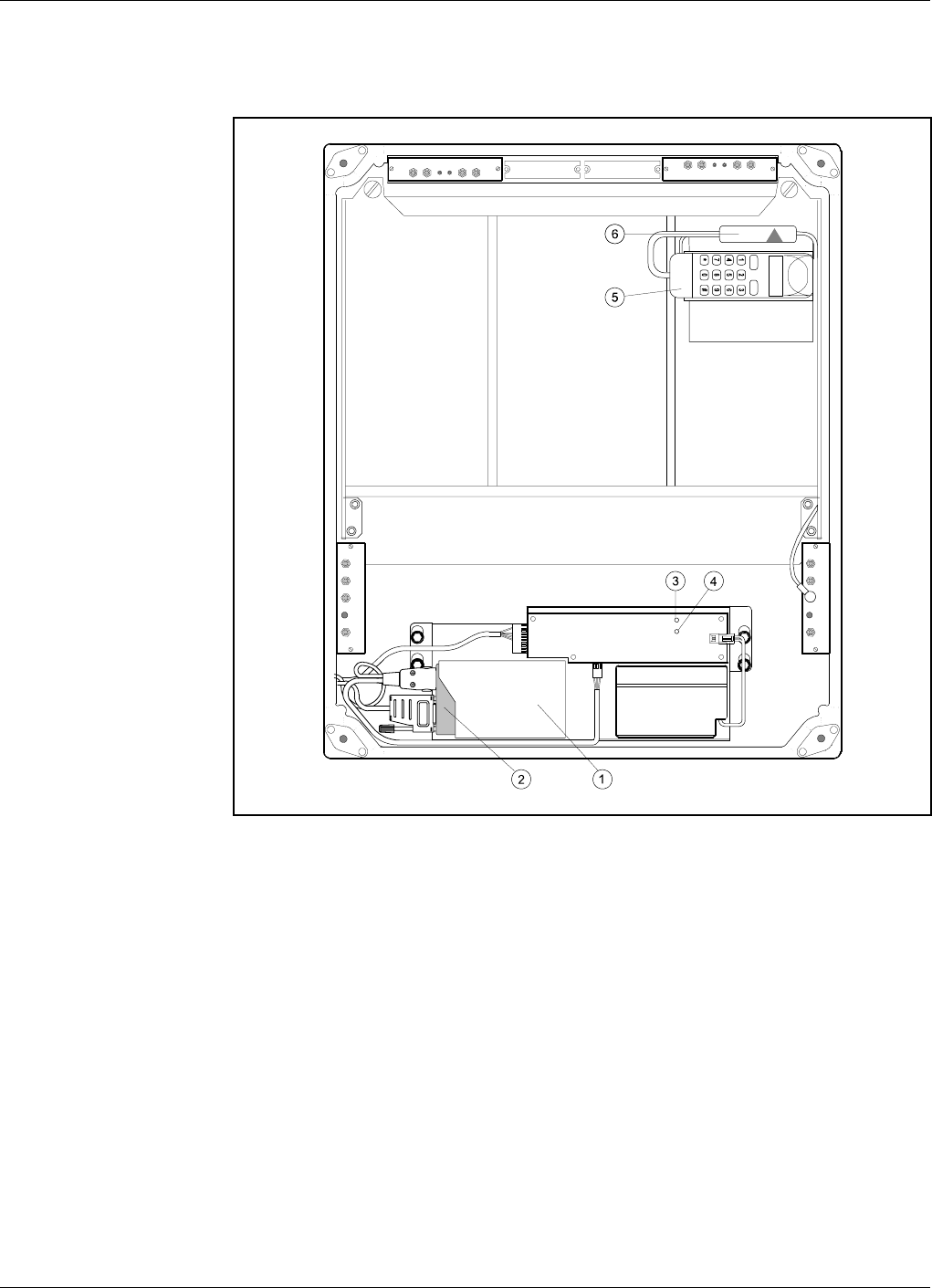
RCU for Wireless Connection
The RCU base unit for Wireless Connection is mounted inside the
repeater cabinet, in front of the PSU (see Figure 6-3).
The bracket for the mobile phone is mounted in the upper right corner of
the cabinet. The mobile phone is placed in the phone holder.
The RCU is connected to the P27 and P32 ports as described in the
Connection section in Chapter 3.
The mobile phone antenna is connected to the MS -20dB port on the BS
directional coupler (DC) located to the right in the cabinet.
The mobile battery charger is connected to the mobile phone.
12volt 0.7Ah
MS
DPX
ANT
TEST
DC
-30 dB
-20 dB
MS
DPX
ANT
TEST
DC
-30 dB
-20 dB
OUT
LOW IN ATT +7V OUT1 OUT2
LNA
UL OUT
LOW
IN+7V ATTOUT1 OUT2
LNA
DL
Figure 6-3. RCU - Wireless PCMCIA type
Optionals AR Repeaters Allgon Systems AB
6 - 6 Rev. P1A 2000-09 User’s Manual VD203 66/EN

RCU kit items - Wireless Connection
The item numbers refer to the numbers in Figure 6-3.
1. PCMCIA modem card host.
2. PCMCIA modem card (not included in the kit).
3. Green LED on the battery charger which is lit with a steady light
when the power supply is OK, either from the mains or from the
battery.
4. Yellow LED on the battery charger which is lit with a steady light
during battery charge from the mains.
5. Mobile phone (not included in the kit) and the phone holder.
6. Battery charger with cable to the mobile phone.
Do not forget to put a jumper between pin 2 and 3 on the P27 connector if
you disconnect the RCU.
Allgon Systems AB AR Repeaters Optionals
User’s Manual VD203 66/EN Rev. P1A 2000-09 6 - 7

OMS, Operation and Maintenance System
The OMS, Operation and Maintenance System is an Allgon software
package for controlling a large repeater fleet by using computers with
Windows NT in networks with a common database.
The OMS is capable of operating a large number of repeaters. Multiple
modems can be used for several incoming and outgoing parallel activities,
such as polling, radio parameter configuration, software downloading, etc.
OMS is an improved OMC, Operation and Maintenance Center. The latter
is replaced by the OMS and is no longer subject to further development.
Traffic Statistics
Traffic statistics is available for channel selective GSM 900, GSM 1900
and DCS/PCN 1800 repeaters, provided that the repeaters have the latest
CU software versions, the latest CU and CHA boards, and that an OMS is
used to poll and view the statistics.
Battery Backup
Battery backup can be arranged by completing the repeater with an
Allgon UPS (Uninterruptible Power Supply). The Allgon UPS has an
exterior similar to the repeater which means that it can preferably be
mounted adjacent to the repeater.
Fiber Optic Interface
A Fiber Optic Interface that includes transmitter, receiver, alarm board
and power supply is available for all the Allgon repeaters. The fiber optic
interface can be adapted for separate uplink and downlink fiber as well as
for bi-directional one-fiber distribution.
7/16" Antenna Cable Connectors
A 7/16" antenna cable kit is available for all the Allgon repeaters. This kit
includes 7/16" antenna connectors for uplink and downlink antennas
mounted on two repeater cable inlet flanges, and cables and connectors
for connection to the DC directional couplers inside the repeater.
Optionals AR Repeaters Allgon Systems AB
6 - 8 Rev. P1A 2000-09 User’s Manual VD203 66/EN
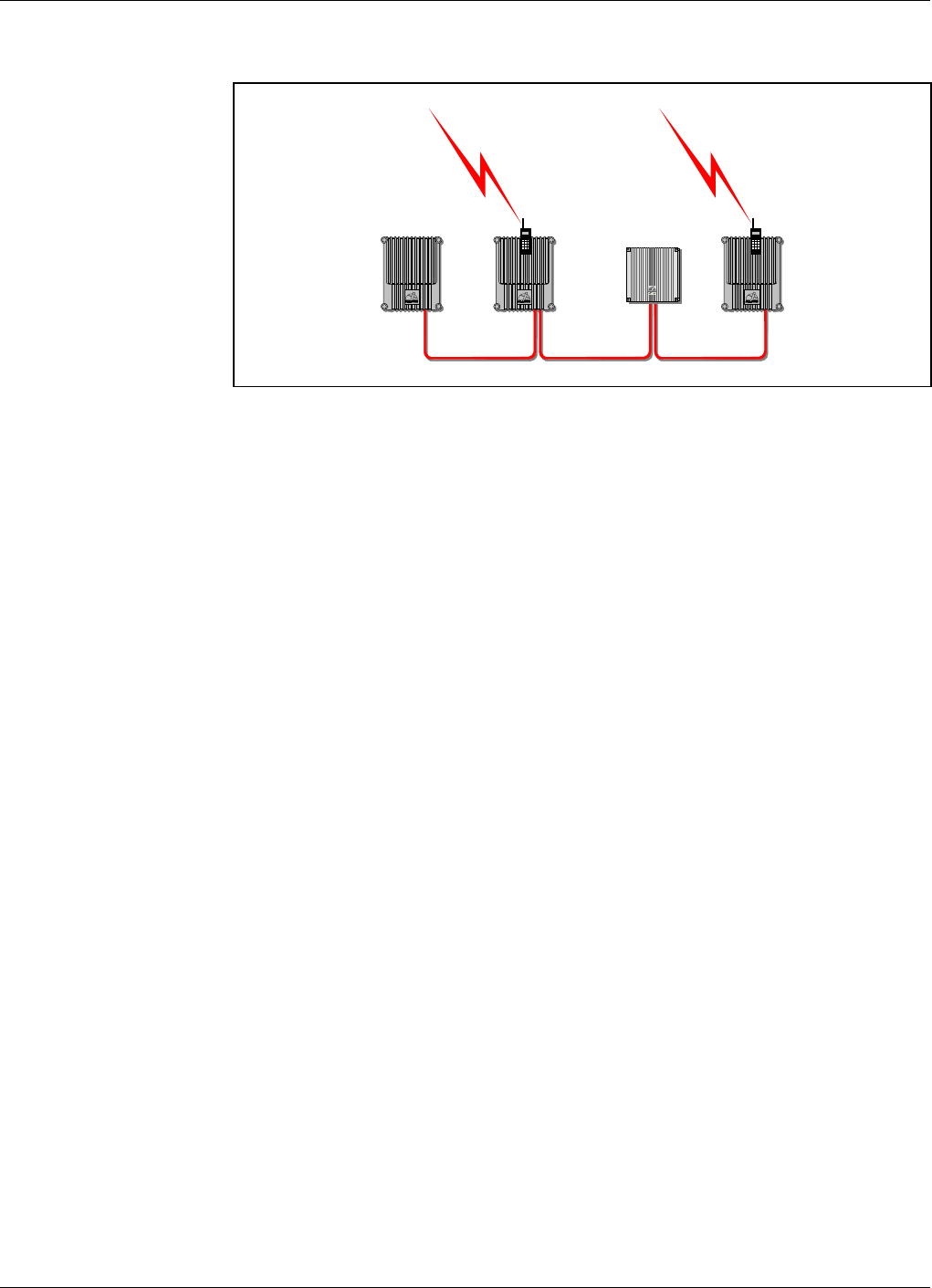
R2R, Repeater To Repeater Link
The Allgon Repeater to Repeater Link can be used in order to establish a
repeater network with up to 13 repeaters, one or several of which can
contain a phone line for communication with an OMT32 or an OMS.
All Allgon repeaters can be included in a R2R net (see Figure 6-4).
Channel selective repeaters, band selective repeaters, and Compact
repeaters can be mixed in the same net. For Compact repeaters, the R2R
Repeater to Repeater Link feature is standard and requires no extra
hardware or software.
AR Repeaters can either be equipped with this feature at the delivery
from Allgon, or be completed with a Repeater to Repeater Link Kit,
provided the repeaters meet the below requirements.
Requirements
To be able to use the Repeater to Repeater Link feature, the following DIA
board, CU board and CU software is required:
DIA board K105/1 version R2A or higher
CU board K103/2 version R1A or higher
CU software SA102 02/1 version R3A or higher
The version of the RIA board can be detected remotely by means of the
OMT32, see the OMT32, User’s Manual.
Further information and requirements are found in the R2R installation
document, R2R, Repeater to Repeater Link Kit, Installation Guide
(part # VD202 91/EN).
Figure 6-4. Repeater to Repeater Link
Allgon Systems AB AR Repeaters Optionals
User’s Manual VD203 66/EN Rev. P1A 2000-09 6 - 9

Installation
The R2R, Repeater to Repeater Link is installed as described in the
R2R, Repeater to Repeater Link Kit, Installation Guide.
At least one RCU unit (or telephone line with modem) is required for
remote communication.
Configuration
Configuration is described in the OMT32, User’s Manual.
Optionals AR Repeaters Allgon Systems AB
6 - 10 Rev. P1A 2000-09 User’s Manual VD203 66/EN

7. Repeater Alarms
This chapter contains a list of those alarms which are initiated in the
repeater and generated by the repeater control circuitry.
Critical, Error and Warning alarms can be sent automatically from a
repeater to an OMT32 and OMS and then be stored. These alarms can
then be viewed.
The alarm handling and facilities are described in the following manuals:
•OMT32, User’s Manual
•Advanced Repeater OMS, User’s Manual
The table starting on the following page contains those alarms that can be
generated by a Compact repeater.
Allgon Systems AB AR Repeaters Repeater Alarms
VD203 66/EN - User’s Manual Rev. P1A 2000-09 7 - 1

Alarm Reference List
The following table contains the internal repeater alarms which can occur
and be shown in the OMT32 and OMS alarm window (additional alarms
may have been added to the system after issuing this manual).
Alarm Text Alarm Unit Alarm Level Description
Antenna isolation BSA # UL/DL Warning Poor antenna isolation
Error Poor antenna isolation at lowest gain
Ceasing The cause of the alarm has ceased
Chan. # UL/DL Warning Poor antenna isolation
Error Poor antenna isolation at lowest gain
Ceasing The cause of the alarm has ceased
Alarm reset CU None Manual alarm reset
Battery backup fault External Error Battery backup fault
Ceasing The cause of the alarm has ceased
CU battery fault CU Warning CU RAM battery fault
Ceasing The cause of the alarm has ceased
Door open alarm 1) External Configurable Door open more than 30 seconds
Ceasing Door closed more than 30 seconds or the alarm is disabled
EEPROM error CU Error EEPROM read or write error
Ext REFO error CU Warning An external reference is lost (e.g. GPS reference)
External alarm 1 External Configurable External alarm input 1 active more than 1 second
Ceasing External alarm input 1 no longer active
External alarm 2 External Configurable External alarm input 2 active more than 1 second
Ceasing External alarm input 2 no longer active
External alarm 3 External Configurable External alarm input 3 active more than 1 second
Ceasing External alarm input 3 no longer active
External alarm 4 External Configurable External alarm input 4 active more than 1 second
Ceasing External alarm input 4 no longer active
Fiber Optical error External Configurable Fiber optic fault
Ceasing The cause of the alarm has ceased
Gain reduction Chan. # UL/DL Warning The gain is reduced below the limit
Ceasing The cause of the alarm has ceased
High temperature BSA #
CHA #
CSA #
Warning The board temperature is higher than 85°C
Error The board temperature is higher than 95°C
Ceasing The board temperature has fallen below 70°C
CU Warning The CU board temperature is higher than 90°C
Ceasing The CU board temperature has fallen below 90°C
Local bus error BSA # Error Communication bus error on BSA board
CHA # Error Communication bus error on CHA board
CSA # Error Communication bus error on CSA board
Log cleared CU None Log memory has been cleared
Log memory fault CU Error Log memory fault
Logon failed CU None Invalid repeater password
Low traffic activity RSSI Statistics Warning No signal strength was above the limit set
Ceasing The cause of the alarm has ceased
Mains breakdown 2) External Critical Power failure
Ceasing Mains power is up again
Mains bkd w backup External Error Mains breakdown - power from battery backup
Ceasing The cause of the alarm has ceased
Modem init failed Remote ctrl None Initiation string to modem not OK
Repeater Alarms AR Repeaters Allgon Systems AB
7 - 2 Rev. P1A 2000-09 VD203 66/EN - User’s Manual

Alarm Text Alarm Unit Alarm Level Description
No BCCH detected RSSI Statistics Warning Signal strength on the BCCH channel was below the limit set
Ceasing The cause of the alarm has ceased
No connection Remote ctrl None No connection at callback
Warning No connection at alarm calling
No modem found Remote ctrl None No modem found
Ceasing Modem found
No phone detected Remote ctrl Warning When using a PC-card modem together with the MS this
alarm indicates contact with the PC-card modem but not
with the MS. The MS may be turned off.
Ceasing The cause of the alarm has ceased
PA fault BSA # Error Low power amplifier gain
CHA # Error Low power amplifier gain
CSA # Error Low power amplifier gain
Param. R/W error BSA # Error EEPROM failure on the BSA board
CHA # Error EEPROM failure on the CHA board
CSA # Error EEPROM failure on the CSA board
Modem PIN failed Remote ctrl Warning The PIN code sent tp MS is incorrect
Ceasing The cause of the alarm has ceased
Power supply PSU1 Critical Power failure in PSU1 (in the cabinet)
Ceasing PSU1 works properly again
PSU2 Critical Power failure in PSU2 (in the cover)
Ceasing PSU2 works properly again
PSU overvoltage BSA # Critical The PA supply voltage is too high
REFO error CU Error Significant REFO drift or error detected by CU
Remote connection Remote ctrl None Remote connection to OMT32 via modem
Remote link timeout Remote ctrl Warning Time limit of 20 min. exceeded without extending timer
Repeater restart CU None Powering up by user or after power failure
Warning Software restart error 1st - 7th time
Error Software restart error 8th - 10th time
RF blocking Chan. # UL Error Constant CW signal >27dBm. PA off.
Ceasing The cause of the alarm has ceased
RTC restarted CU None The time is changed by the operator
Warning Date set to 1994-01-01
RTC error CU Error RTC does not operate properly
Startup error BSA # Error Hardware error on BSA board
CHA # Error Hardware error on CHA board
CSA # Error Hardware error on CSA board
SW load error CU Error Software load error
Unsupported PA type CSA # Error Mounted PA board ID is not expected by the BSA board
Synthesizer fault BSA # Error Synthesizer unlocked on the BSA board
CHA # Error Synthesizer unlocked on the CHA board
CSA # Error Synthesizer unlocked on the CSA board
Volt Reg. fault BSA # Error Missing DC voltage on the BSA board
CHA # Error Missing DC voltage on the CHA board
CSA # Error Missing DC voltage on the CSA board
Remarks
1) The Door open alarm requires an optional door switch described in the P33 Alarm Port section in Chapter 3.
2) The Mains breakdown alarm requires a relay not included in the repeater (see Mains Breakdown Relay in Chapter 3).
Chan. #, UL/DL Repeater channel number (1-4) at channel selective operation, uplink or downlink.
BSEL #, UL/DL Repeater channel number at band selective operation, uplink or downlink.
CHA # CHA board number at channel selective operation.
CSA # CSA board number at channel selective CDMA operation.
BSA # BSA board number at band selective operation.
Allgon Systems AB AR Repeaters Repeater Alarms
VD203 66/EN - User’s Manual Rev. P1A 2000-09 7 - 3

Index
A
Abbreviations ............................................................................................................... vi
AGC, Automatic Gain Control ....................................................................... 5-13, 5-15
Alarm ........................................................................................................................ 5-16
Alarm reference list ................................................................................................... 7-2
ALARM, red LED ...................................................................................................... 4-2
ALI, Alarm Interface board ............................... 5-3 - 5-8, 5-16, 5-23 - 5-24, 6-3 - 6-4
AMPS ................................................................................................................. 2-2, 5-14
Antenna cable connectors, 7/16" ............................................................................... 6-8
AUX1 auxiliary connector ....................................................................................... 5-23
B
BA, Booster Amplifier board ........................................ 5-2, 5-6, 5-13, 5-18, 5-21, 5-31
Battery backup ........................................................................................................... 6-8
Block diagram
band selective repeater ...................................................................................... 5-14
channel selective CDMA repeater ..................................................................... 5-12
channel selective GSM type repeater ............................................................... 5-10
BOOT, red LED ......................................................................................................... 4-2
BSA, Band Selective Amplifier board .............. 5-2, 5-7 - 5-8, 5-14, 5-22 - 5-24, 5-32
C
Cabling ...................................................................................................................... 5-27
band selective repeater ...................................................................................... 5-32
channel selective CDMA repeater ..................................................................... 5-30
channel selective GSM type repeater, 2 ch. ..................................................... 5-28
channel selective GSM type repeater, 4 ch. ..................................................... 5-29
channel selective high power CDMA repeater ................................................. 5-31
CDMA .................................................................................. 2-2, 5-12, 5-21, 5-30 - 5-31
CHA, Channel Amplifier board .................................. 5-2, 5-4, 5-8, 5-10, 5-18 - 5-20,
5-23 - 5-24, 5-28 - 5-29
CMB, Combiner unit .................................................... 5-3 - 5-4, 5-8, 5-11, 5-18, 5-20
Commissioning ........................................................................................................... 4-1
Connection .................................................................................................................. 3-7
donor antenna ....................................................................................................... 3-7
external alarm ....................................................................................................... 3-8
internal phone/modem unit ................................................................................. 3-8
mains ..................................................................................................................... 3-7
RCU ....................................................................................................................... 3-8
Repeater to Repeater Link .................................................................................. 3-9
service antenna ..................................................................................................... 3-7
telephone line ........................................................................................................ 3-8
Connection ports ...................................................................................................... 3-10
CSA, CDMA Segment Amplifier board ...................... 5-2, 5-5 - 5-6, 5-12, 5-19, 5-21,
5-23 - 5-24, 5-30 - 5-31
CU software
version ...................................................................................................... 5-25 - 5-26
CU software and hardware compatibility .............................................................. 5-26
CU, Control Unit board ......... 5-3 - 5-8, 5-13, 5-15 - 5-16, 5-23 - 5-26, 6-3 - 6-4, 6-8
Allgon Systems AB AR Repeaters Index
VD203 66/EN - User’s Manual Rev. P1A 2000-09 I - 1

D
DAMPS .............................................................................................................. 2-2, 5-14
DC, Directional Coupler ............. 3-8, 4-4, 5-3 - 5-8, 5-10 - 5-15, 5-17 - 5-18, 6-6, 6-8
DCS ..................................................................................................... 2-2, 5-10, 6-4, 6-8
DIA, Distribution board ....................................................... 3-10, 5-3, 5-19, 5-23, 5-25
Dimensions .................................................................................................................. 3-2
DLSee Downlink
Donor antenna .................................................................................. 2-4 - 2-5, 3-6 - 3-7
Door switch ..................................................................................................... 3-13, 5-23
Downlink ............................................................................. 5-9 - 5-10, 5-12, 5-14, 5-19
DPX, Duplex filter .................................................... 5-3 - 5-8, 5-10 - 5-15, 5-17 - 5-22
E
EAL1 .......................................................................................................................... 3-12
EAL2 .......................................................................................................................... 3-12
EAL3 .......................................................................................................................... 3-12
EAL4 ............................................................................................................... 3-12 - 3-13
ESD .............................................................................................................................. 1-2
ETACS ............................................................................................................... 2-2, 5-14
External alarm ............................................................................................................ 3-8
External alarm input ............................................................................................... 3-12
F
Fiber Optic Interface .................................................................................................. 6-8
Functional description ............................................................................................... 5-1
G
GSM ............................................................... 2-2, 5-10, 5-18, 5-28 - 5-29, 6-2, 6-4, 6-8
H
Hail .............................................................................................................................. 3-1
I
Indicators in the cabinet ............................................................................................ 4-3
Indicators on the repeater front ............................................................................... 4-2
Introduction ................................................................................................................ 2-1
L
LNA, Low Noise Amplifier .............................. 5-3 - 5-8, 5-10, 5-12, 5-14, 5-18 - 5-24
M
Mains breakdown relay ............................................................................................ 3-15
Mounting ............................................................................................................ 3-4 - 3-6
Mounting bracket .............................................................................................. 3-4 - 3-6
N
NMT .................................................................................................................. 2-2, 5-14
Index AR Repeaters Allgon Systems AB
I - 2 Rev. P1A 2000-09 VD203 66/EN - User’s Manual

O
OMS, Operation and Maintenance System ...................................................... 2-1, 6-8
OMT32, Operation and Maintenance Terminal ..................................................... 2-1
OPER, green LED ..................................................................................................... 4-2
Outdoor installation .................................................................................................. 3-1
Output power level .................................................................................................... 4-4
P
PA, Power Amplifier board . 5-2, 5-5 - 5-8, 5-13, 5-15, 5-18, 5-21 - 5-24, 5-30 - 5-32
PCMCIA ...................................................................................................... 6-4 - 6-5, 6-7
PCN ..................................................................................................... 2-2, 5-10, 6-4, 6-8
PCS .............................................................................................................................. 2-2
Ports
+7V ...................................................................................................................... 5-19
AI ..................................................................................................... 3-12 - 3-13, 3-15
ANT .......................................................................................................... 5-17 - 5-18
AO ........................................................................................................................ 3-13
ATT ...................................................................................................................... 5-19
DPX ........................................................................................................... 5-17 - 5-18
HI ..................................................................................................... 5-18, 5-20 - 5-22
IN .............................................................................................................. 5-18 - 5-19
LO ............................................................................................................. 5-18 - 5-22
MRX ..................................................................................................................... 5-17
MS -20dB ....................................................................................... 3-8, 5-17, 6-2, 6-6
OUT LOW ........................................................................................................... 5-19
OUT1 ........................................................................................................ 5-19 - 5-22
OUT2 ........................................................................................................ 5-19 - 5-20
P101 .......................................................................................................... 5-19 - 5-22
P11 ....................................................................................................................... 5-23
P12 ....................................................................................................................... 5-23
P13 ....................................................................................................................... 5-23
P14 ....................................................................................................................... 5-23
P2 ................................................................................................................ 5-23, 5-25
P21 ....................................................................................................................... 5-23
P22 ....................................................................................................................... 5-23
P23 .............................................................................................................. 5-19, 5-23
P24 .............................................................................................................. 5-19, 5-23
P25 Expansion .................................................................................................... 5-23
P26 Expansion .................................................................................................... 5-23
P27 Auxiliary ......................................... 3-8, 3-11, 5-15, 5-23 - 5-24, 6-2, 6-5 - 6-7
P28 Door switch ........................................................................................ 3-13, 5-23
P3 ................................................................................................................ 5-21, 5-23
P301 .......................................................................................................... 5-21 - 5-22
P31 PC ....................................................................................... 3-9, 3-11, 5-16, 5-23
P32 Modem ............................................ 3-8, 3-12, 5-15 - 5-16, 5-23, 6-2, 6-5 - 6-6
P33 Alarm ............................................................ 3-8, 3-12 - 3-13, 3-15, 5-16, 5-23
P34 Repeater to Repeater Link ...................................................... 3-14, 5-15, 5-23
P4 ..................................................................................................... 5-18, 5-21 - 5-23
P5 ..................................................................................................... 5-18, 5-21 - 5-23
P701 ............................................................................................................ 5-18, 5-20
TEST -30dB ................................................................................................. 4-4, 5-17
Power Supply Unit, 24 or 48 Volt DC ................................................................... 3-16
PSU, Power Supply Unit ........................................................................ 5-3 - 5-8, 5-23
PWR, yellow LED ...................................................................................................... 4-2
Allgon Systems AB AR Repeaters Index
VD203 66/EN - User’s Manual Rev. P1A 2000-09 I - 3

R
R2R, Repeater to Repeater Link .................................................... 3-14, 4-3, 5-15, 6-9
Rain .............................................................................................................................. 3-1
RCU, Remote Control Unit ............................................................................. 5-3, 5-15
RCU, Remote Control Unit for GSM 900 ................................................................ 6-2
RCU, Remote Control Unit with PCMCIA modem ................................................. 6-4
Repeater CU hardware version ............................................................................... 5-25
Repeater CU software version ................................................................................. 5-25
Repeater design .......................................................................................................... 5-2
Repeater setup .......................................................................................................... 5-16
Repeater to Repeater Link
See R2R, Repeater to Repeater Link
Repeater types
Band selective repeater, adjustable band width ................................................. 2-2
Band selective repeater, fixed band width .......................................................... 2-2
Channel selective CDMA repeater ....................................................................... 2-2
Channel selective GSM repeater .......................................................................... 2-2
Channel selective high power CDMA repeater .................................................. 2-2
Combined repeater ................................................................................................ 2-2
RFI filter ........................................................................................................ 5-20 - 5-22
RIA, Repeater to Repeater Interface adapter .......................................................... 5-3
S
Safety ........................................................................................................................... 1-1
beryllium oxide ...................................................................................................... 1-1
electric shock ......................................................................................................... 1-1
lithium battery ...................................................................................................... 1-1
polytetrafluoro ethylene ....................................................................................... 1-1
PTFE ...................................................................................................................... 1-1
Service antenna ................................................................................ 2-4 - 2-5, 3-6 - 3-7
Service limitations ...................................................................................................... 3-1
Shelter ......................................................................................................................... 3-1
Siting the repeater ..................................................................................................... 3-1
Snow ............................................................................................................................ 3-1
Static electricity .......................................................................................................... 1-2
Station ground .......................................................................................................... 3-10
Sunshine ...................................................................................................................... 3-1
Supply voltage ............................................................................................................. 4-4
T
TACS ................................................................................................................. 2-2, 5-14
Testpoints .......................................................................................................... 4-4, 5-24
Traffic statistics .......................................................................................................... 6-8
U
ULSee Uplink
Uplink ................................................................................................................ 5-9, 5-19
UPS .............................................................................................................................. 6-8
W
Warning signs ............................................................................................................. 1-2
Weights ........................................................................................................................ 3-2
Index AR Repeaters Allgon Systems AB
I - 4 Rev. P1A 2000-09 VD203 66/EN - User’s Manual

Questionnaire
The aim of this manual is to guide you when installing and operating the
Allgon repeaters, and to answer questions that may turn up. To ensure
that we provide appropriate information for these purposes, we would
appreciate your views and suggestions on how to improve the manual in
this direction. Please, fill out the following questionnaire and send it to
us.
1Have you read entire sections or do you use the manual to look up specific
information when needed?
q Read entire sections q Look up specific information
Comments:
2Do you think the information is easy to find and understand?
q Yes q No
Comments:
3Do you find any function of the Allgon repeater hard to understand, a
function which should be subjected to more detailed description?
q Yes q No
If yes, which one:
4Do you have any suggestions on how we can improve this manual?
Title (Mr/Ms/Other): Initial:
Surname: Job title:
Company: Address:
City: Country: Phone:
Thanks for your kind help. It’s very valuable to us.
Allgon Systems AB AR Repeaters Questionnaire
VD203 66/EN - User’s Manual Rev. P1A 2000-09 Q - 1

Allgon Systems AB
Customer Support Centre
SE-187 80 Täby
Sweden
If you prefer to send by mail, fold here and tape.
No envelope required.
If you prefer to send by fax, use this number: +46 8 540 834 80
POSTAGE
STAMP
Questionnaire AR Repeaters Allgon Systems AB
Q - 2 Rev. P1A 2000-09 VD203 66/EN - User’s Manual