Powerwave Technologies BDA1200 Bi-directional Amplifier, Model BDA1200 User Manual revised manual
Powerwave Technologies Inc. Bi-directional Amplifier, Model BDA1200 revised manual
UserManual.wiki
>
Powerwave Technologies
>
BDA1200 User Manual
>
revised manual
Contents
1.
Test and alignment spec for booster
2.
test and alignment spec for power amplifier
3.
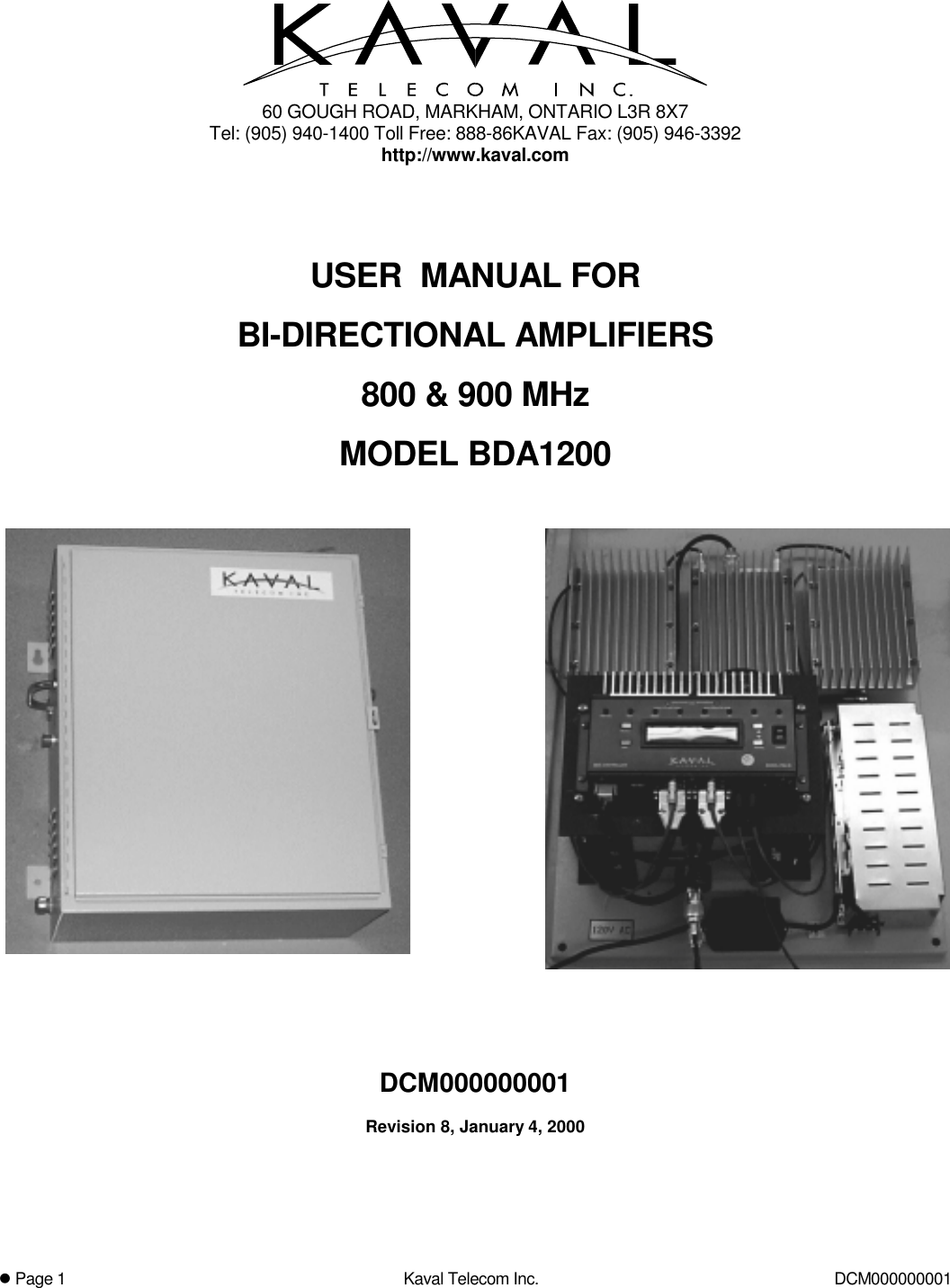
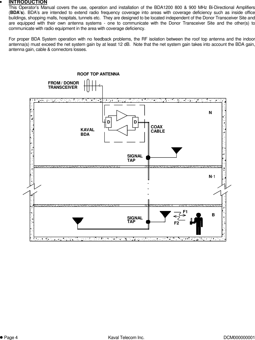
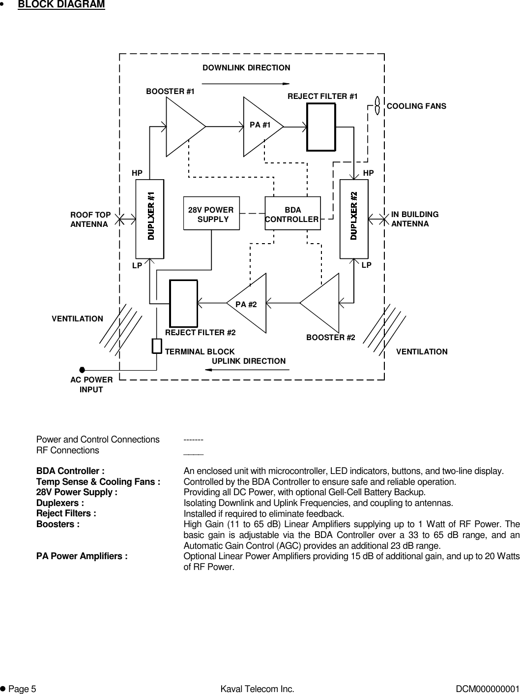
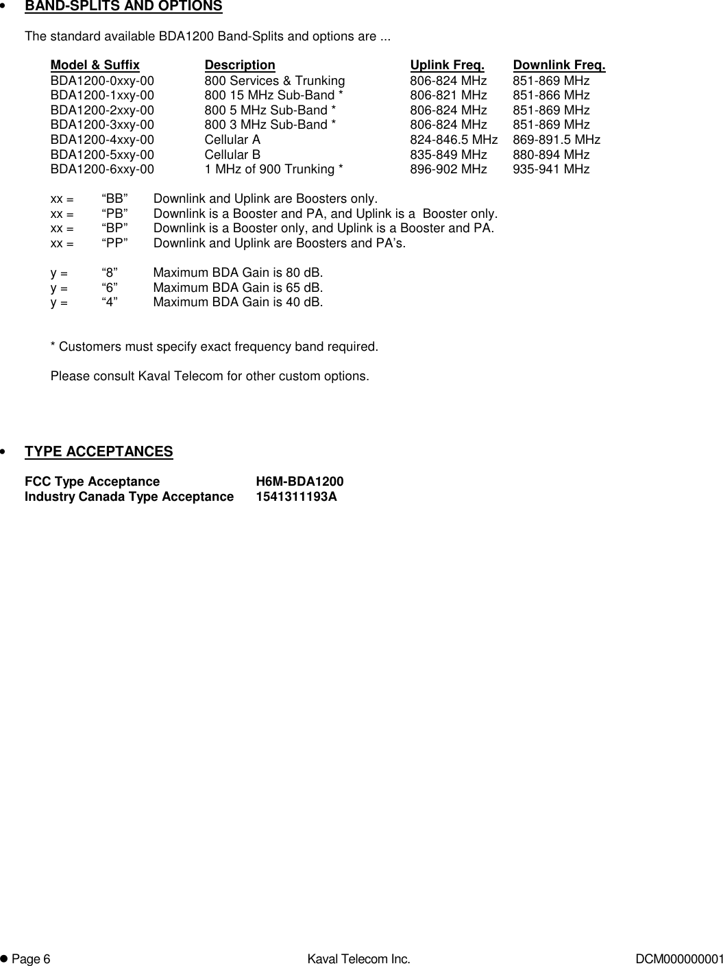
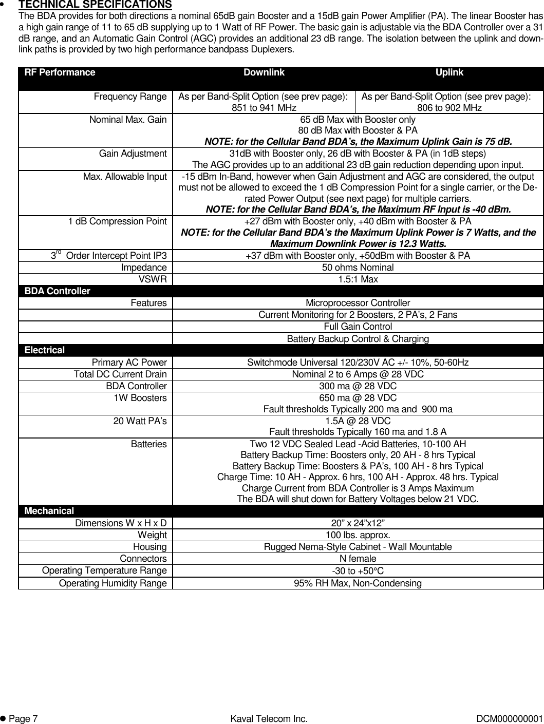
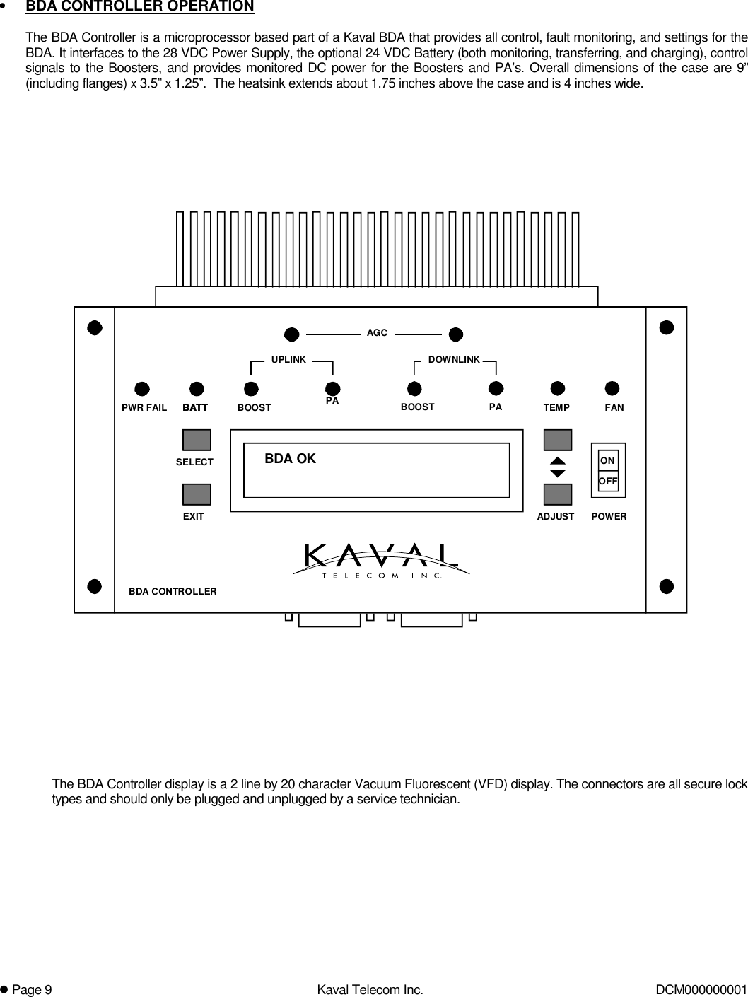
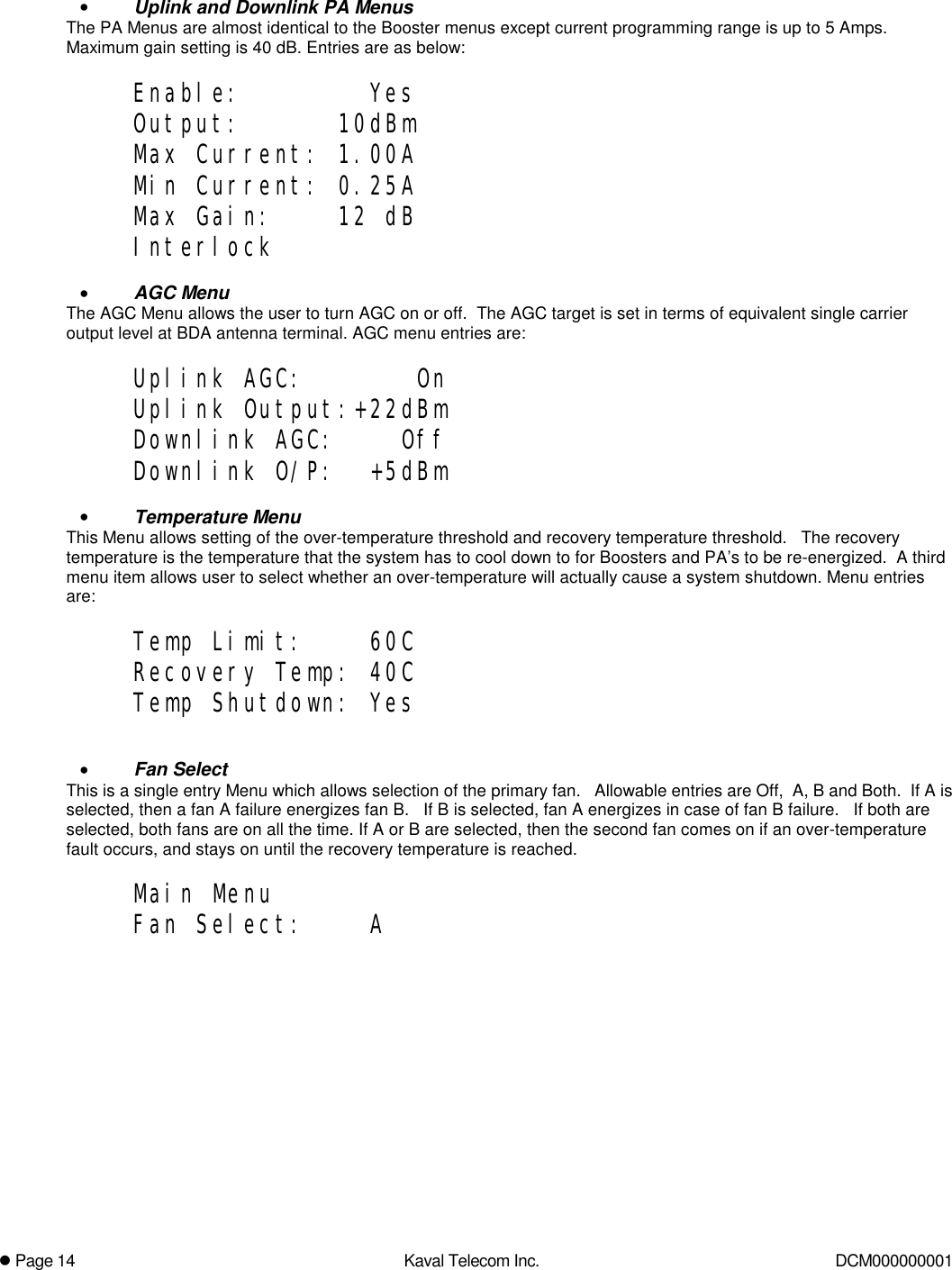
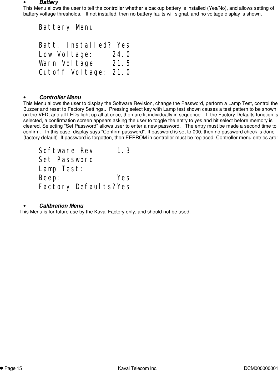
users manual
4.
test and alignment for booster
5.
test and alignment for power amplifier
6.
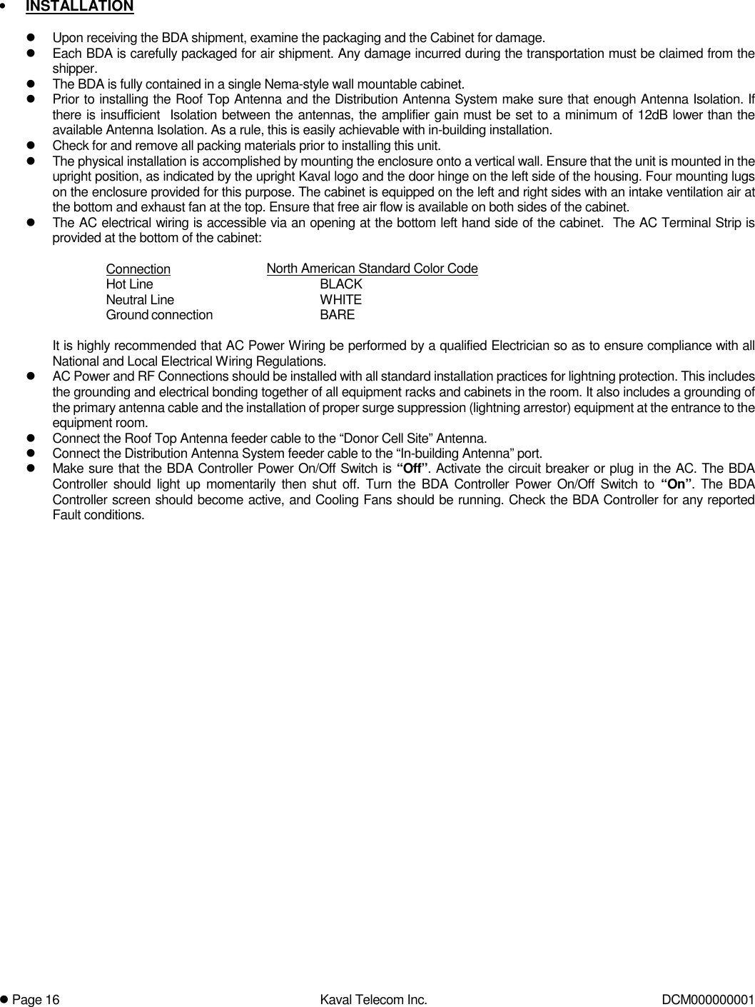
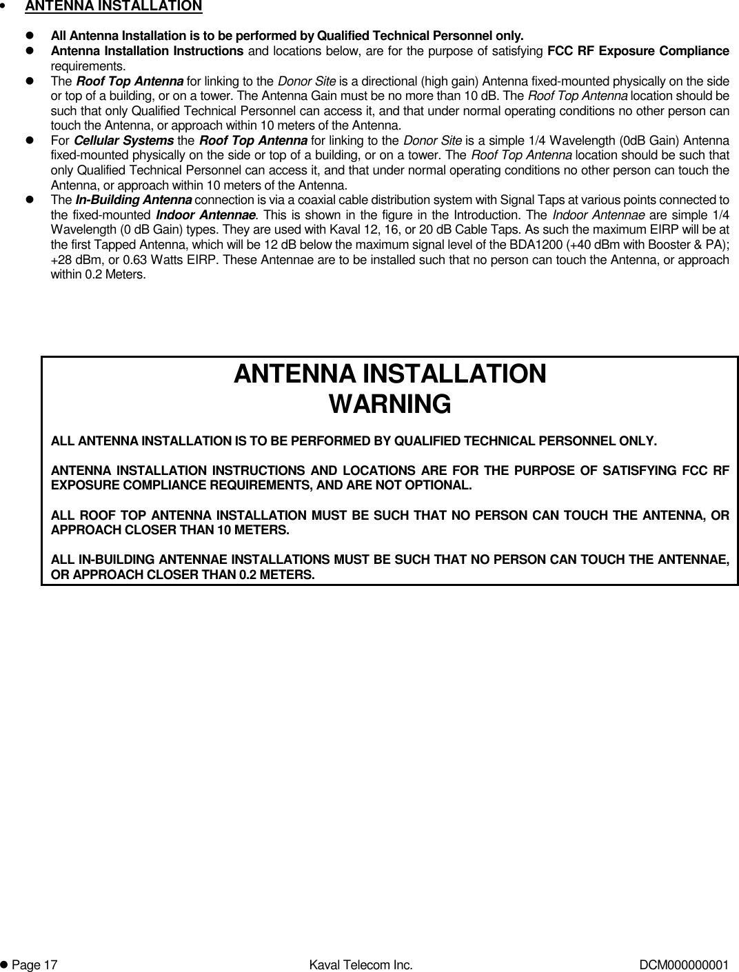
antenna installation
7.
Corrected page 17 of users maunal
8.
revised manual
revised manual
Navigation menu
Upload a User Manual
Namespaces
Wiki Guide
HTML
PDF
Info
Views
User Manual
Discussion / Help
Navigation