Powerwave Technologies BDA1300 BDA-1300 User Manual Users manual
Powerwave Technologies Inc. BDA-1300 Users manual
UserManual.wiki
>
Powerwave Technologies
>
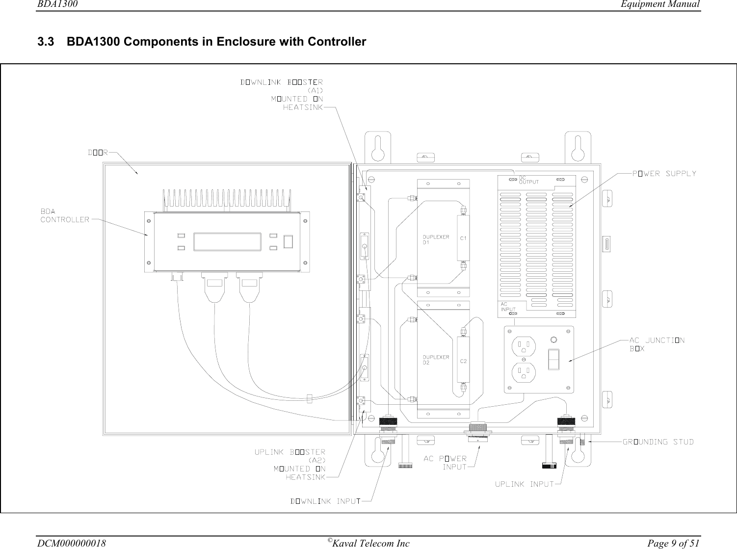
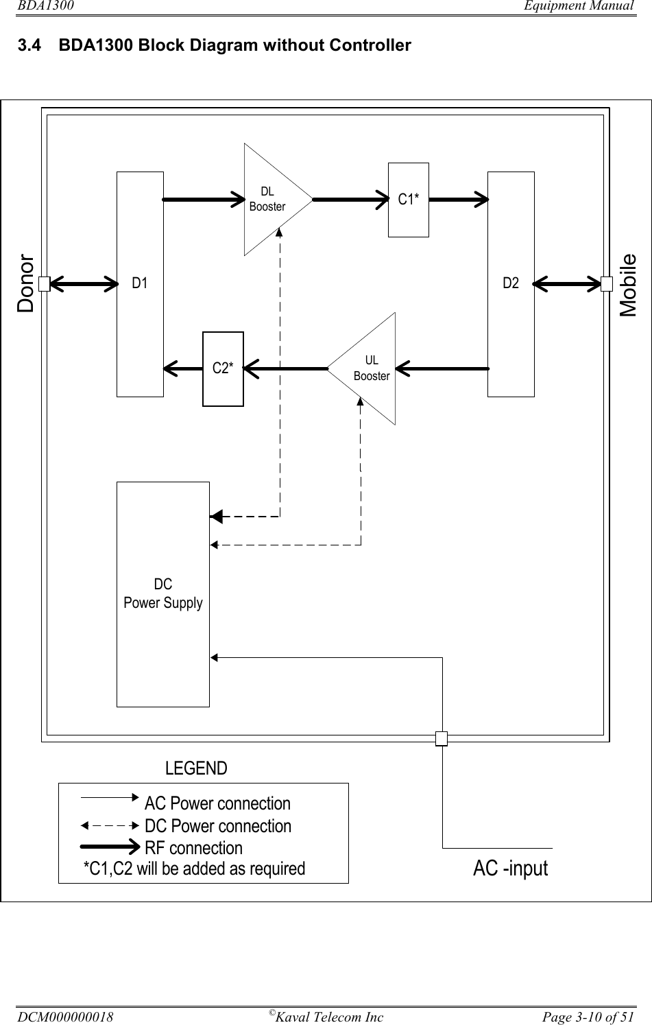
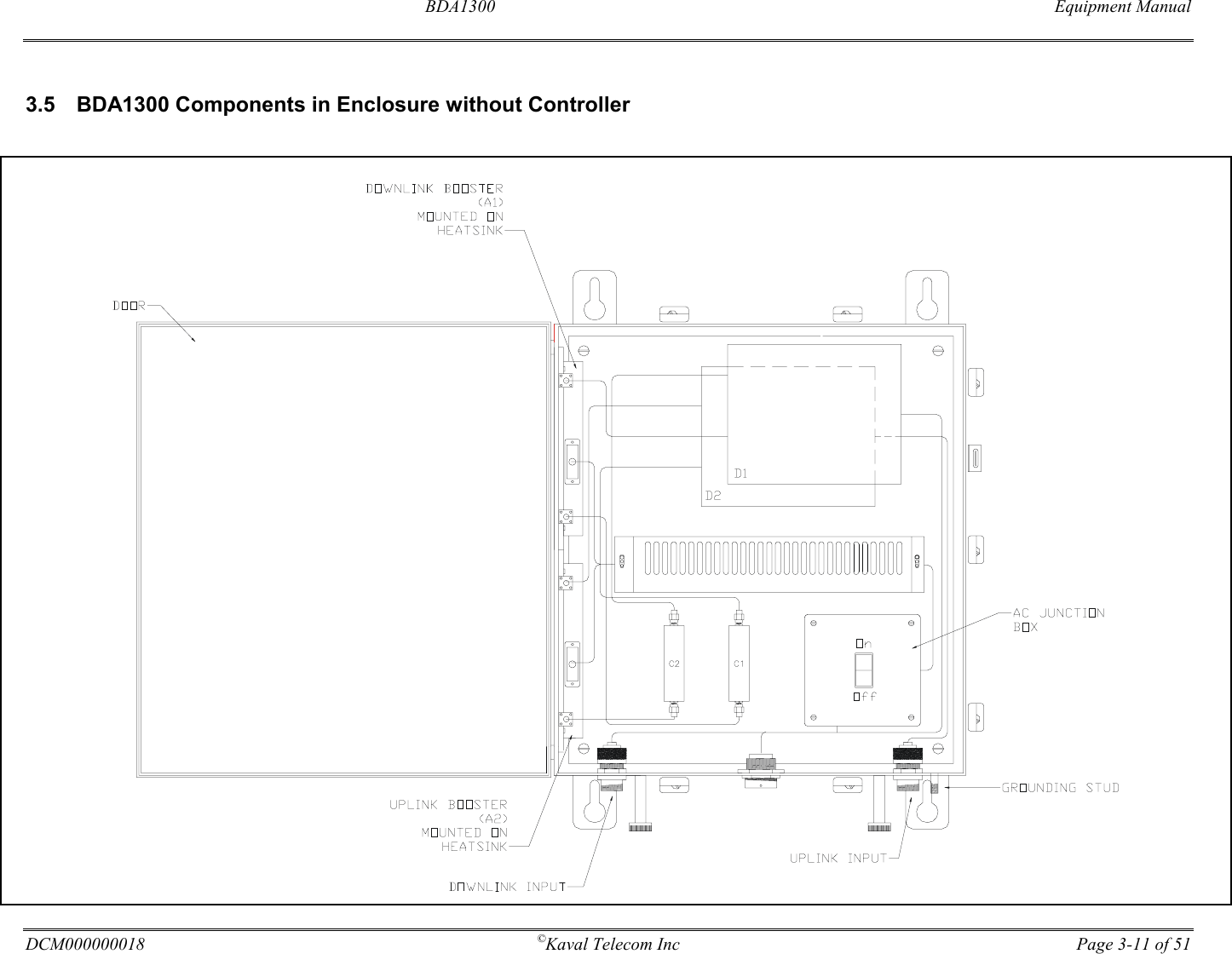
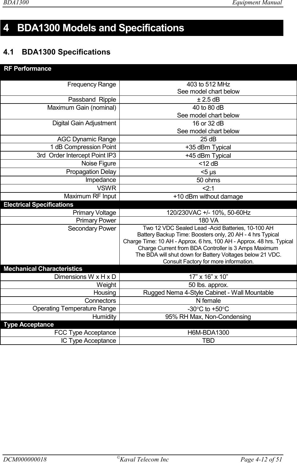
BDA1300 User Manual
Users manual
Navigation menu
Upload a User Manual
Namespaces
Wiki Guide
HTML
PDF
Info
Views
User Manual
Discussion / Help
Navigation