Powerwave Technologies BDA1300 BDA-1300 User Manual Users manual
Powerwave Technologies Inc. BDA-1300 Users manual
Users manual
Document Number: DCM000000018, Rev.0
Issue March 21, 2000
© Copyright 2000 Kaval Telecom Inc. All Rights Reserved
1.1 A-1200-0BB4-01
BDA1300
BI-DIRECTIONAL AMPLIFIER
UHF 403-512 MHz
EQUIPMENT MANUAL

DCM000000018
Kaval Telecom Inc. iii
Proprietary Statement
©2000 Kaval Telecom Inc. All rights reserved. No part of this publication, or any
software included with it may be reproduced, stored in a retrieval system, or
transmitted in any form or by any means, including photocopying, electronic,
mechanical, recording or otherwise, without the prior written permission of the
copyright holder.
This document contains proprietary information of Kaval Telecom Inc. The contents
are confidential and any disclosure to persons other than the officers, employees,
agents or subcontractors of the owner or licensee of this document, without the prior
written consent of Kaval Telecom Inc., is strictly prohibited.
Kaval Telecom Inc. provides this document as is, without any warranty of any
kind either expressed or implied including, but not limited to, the implied
warranties of merchantability and fitness of a particular purpose. Kaval Telecom
may make changes or improvements in the equipment, software, or
specifications described in this document at any time and without notice. These
changes will be incorporated in new releases of this document.
This document may contain technical inaccuracies or typographical errors. Kaval
Telecom Inc. waives responsibility for any labour, materials, or costs incurred by
any person or party as a result of using this document. Kaval Telecom Inc., and
any of its affiliates shall not be liable for any damages (including, but not limited
to, consequential, indirect or incidental, special damages or loss of profits or
date) even if they were foreseeable and Kaval Telecom has been informed of
their potential occurrence, arising out of or in connection with this document or its
use.
Kaval Telecom Inc.
60 Gough Road,
Markham. Ontario.
L3R 8X7
Tel : (905)940-1400
Fax : (905)940-1402
http://www.kaval.com/

DCM000000018
Kaval Telecom Inc. iv
TABLE OF CONTENTS
1 FCC NOTICE............................................................................................................................ V
2 INTRODUCTION TO BDA’S................................................................................................. 2-4
2.1 BDA LINE AMPLIFIER SYSTEM APPLICATION...................................................................................... 2-4
2.2 BDA LINE AMPLIFIER DIAGRAM ........................................................................................................ 2-4
2.3 BDA “OFF-THE-AIR” AMPLIFIER SYSTEM APPLICATION ...................................................................... 2-5
2.4 BDA “OFF-THE-AIR” DRAWING ........................................................................................................ 2-5
3 BDA1300 BI-DIRECTIONAL AMPLIFIER DESCRIPTION.................................................. 3-6
3.1 BDA1300 FUNCTIONAL DESCRIPTION .............................................................................................. 3-6
3.2 BDA1300 BLOCK DIAGRAM WITH CONTROLLER ................................................................................ 3-7
3.3 BDA1300 COMPONENTS IN ENCLOSURE WITH CONTROLLER ................................................................. 9
3.4 BDA1300 BLOCK DIAGRAM WITHOUT CONTROLLER ........................................................................ 3-10
3.5 BDA1300 COMPONENTS IN ENCLOSURE WITHOUT CONTROLLER ...................................................... 3-11
4 BDA1300 MODELS AND SPECIFICATIONS .................................................................... 4-12
4.1 BDA1300 SPECIFICATIONS ........................................................................................................... 4-12
4.2 BDA1300 SERIES MODEL CHART.................................................................................................. 4-13
4.3 POWER DE-RATING REQUIREMENTS............................................................................................... 4-14
4.4 AUTOMATIC GAIN CONTROL (AGC) ................................................................................................ 4-14
4.5 AGC THRESHOLD LEVEL SETTING.................................................................................................. 4-14
4.6 BDA PER CHANNEL POWER DE-RATING & AGC THRESHOLD SETTING............................................. 4-15
5 BDA ENCLOSURE INSTALLATION ................................................................................. 5-16
5.1 PREPARATION FOR THE INSTALLATION OF BDA ENCLOSURES ............................................................ 5-16
5.2 MOUNTING THE BDA ENCLOSURE .................................................................................................. 5-16
5.3 CONNECTING THE COAXIAL CABLES ................................................................................................ 5-16
5.4 BDA ENCLOSURE OUTLINE ........................................................................................................... 5-21
5.5 RF AND POWER CONNECTIONS......................................................................................................... 22
5.6 CONNECTING THE POWER CABLES .................................................................................................... 23
5.7 SECURING THE DOOR....................................................................................................................... 23
6 ANTENNA INSTALLATION .................................................................................................. 24
7 BDA CONTROLLER AND CONFIGURATION ..................................................................... 25
7.1 BDA1300 CONTROLLER OPERATION ................................................................................................ 25
7.2 BDA CONTROLLER DRAWING ........................................................................................................... 25
7.3 BDA CONTROLLER USER INTERFACE ............................................................................................... 26
7.4 CHECKING BDA STATUS .................................................................................................................. 27
7.5 SETTING BDA OPERATING PARAMETERS ........................................................................................... 27
7.6 BDA CONTROLLER FIELD SETTINGS PARAMETERS ............................................................................. 28
7.7 BDA CONTROLLER CONFIGURATION GUIDE ....................................................................................... 29
7.8 EXAMPLE - SETTING THE DOWNLINK GAIN .......................................................................................... 48
8 TROUBLESHOOTING AND MAINTENANCE ...................................................................... 49
8.1 MAINTENANCE & SAFETY.................................................................................................................. 49
8.2 MAINTENANCE PHILOSOPHY.............................................................................................................. 49
8.3 TROUBLESHOOTING PROCEDURE ...................................................................................................... 49
9 STANDARD WARRANTY ..................................................................................................... 52
10 PRODUCT SERVICE PROCEDURE ................................................................................. 53
11 ORDERING PARTS AND ACCESSORIES ....................................................................... 54
12 GLOSSARY........................................................................................................................55

DCM000000018
Kaval Telecom Inc. v
1 FCC NOTICE
NOTE:
This equipment has been tested and found to comply with the limits for a
Class A digital device, pursuant to Part 15 of the FCC Rules. These limits are
designed to provide reasonable protection against harmful interference when
the equipment is operated in a commercial environment. This equipment
generates, uses, and can radiate radio frequency energy and, if not installed
and used in accordance with the instruction manual, may cause harmful
interference to radio communications. Operation of this equipment in a
residential area is likely to cause harmful interference in which case the user
will be required to correct the interference at his own expense.
WARNING:
Changes or modifications not expressly approved by Kaval Telecom Inc.
could void the user’s authority to operate the equipment.
BDA1300 Equipment Manual
DCM000000018 ©Kaval Telecom Inc. Page 2-4 of 51
2 INTRODUCTION TO BDA’s
Bi-Directional Amplifiers (BDA’s) are radio frequency amplifiers that amplify signals in two
directions. There are two basic BDA Applications; Line Amplifiers and “Off-the-Air”...
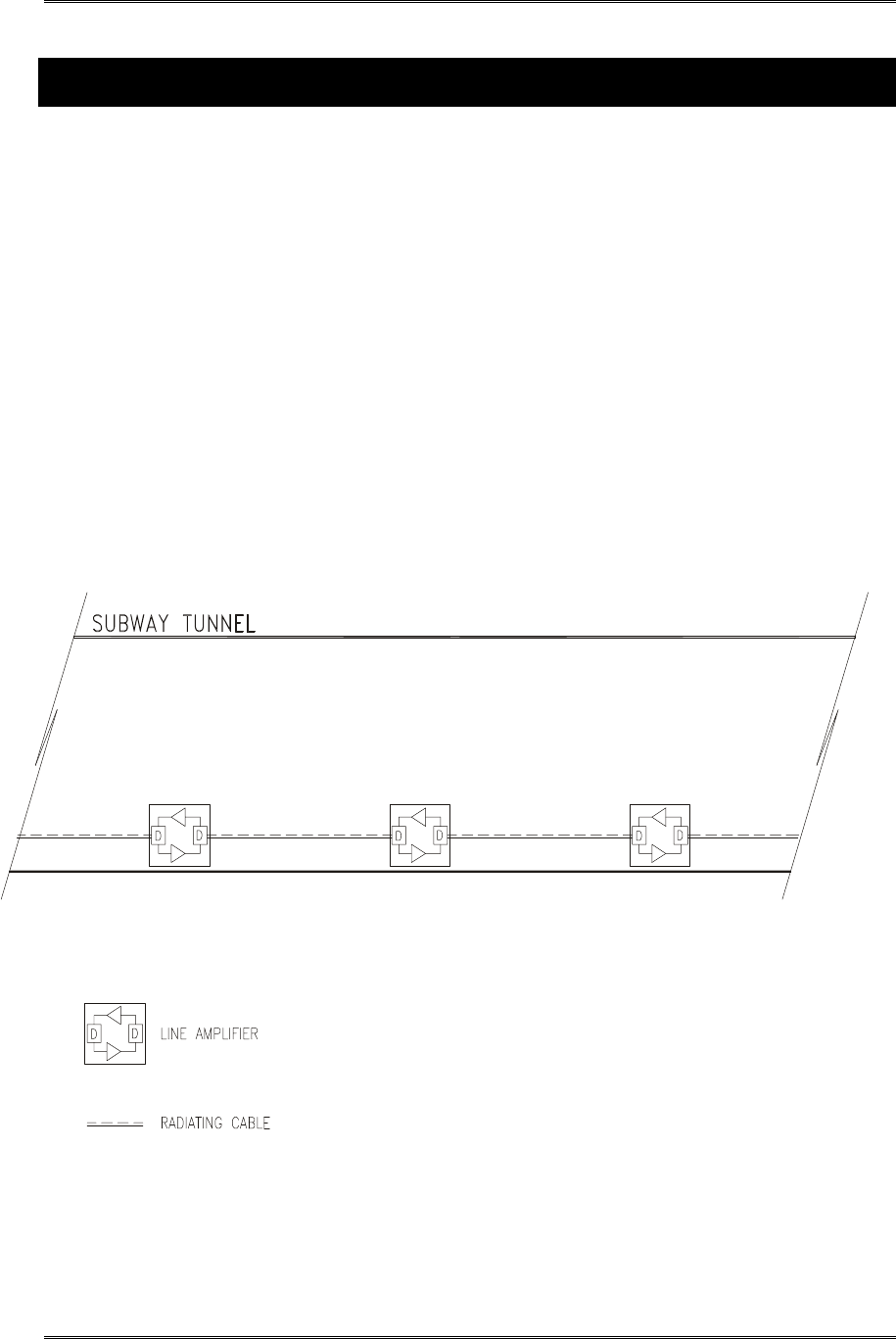
2.1 BDA Line Amplifier System Application
In-building RF distribution system usually takes on one of several forms including, but limited to,
radiating cable, distributed tapped radiators, or high power repeater antennas. For in-building RF
distribution system that requires some gain to compensate for the system loss, line amplifier is the best
device for the job. Line Amplifiers provides amplifications of RF signals to recover signal loss
contributed by radiating cable and other system components.
Figure 1-1 shows an example of a subway tunnel RF distribution system using Line Amplifiers. The
system consists of Line Amplifiers strategically inserted between radiating cables. As the RF signal
travelling along the radiating cable, it loses strength because some of its energy is converted into heat.
Line amplifiers recover the RF loss by amplifying the signal to the desired signal strength before
sending it down the next section of radiating cables. Hence, the in-building RF seamless coverage can
be maintained.
2.2 BDA Line Amplifier Diagram
BDA1300 Equipment Manual
DCM000000018 ©Kaval Telecom Inc. Page 2-5 of 51
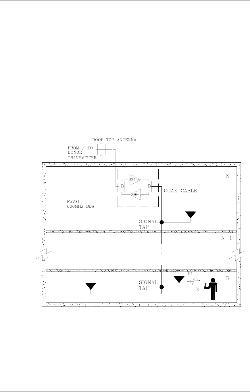
2.3 BDA “Off-the-Air” Amplifier System Application
The Bi-Directional Amplifier is intended to extend Cellular coverage into areas with coverage
deficiency such as inside office buildings, shopping malls, hospitals etc. It is designed to be
located independent of the donor site and must be equipped with its own antenna systems - one
to communicate with the donor site and the other(s) to communicate with portables in the shadow
zone.
A typical in-building coverage extension system is shown in Figure 1-2. The head-end subsystem,
namely Kaval bi-directional amplifier, is responsible for the amplification of both incoming “off-the-air”
downlink signal and outgoing uplink signals. The in-building distribution antenna system comprises of
Coaxial cable, Signal taps, splitters and antennas to extend coverage on every floor, basement and
underground parking garage.
2.4 BDA “Off-the-Air” Drawing
This distributed antenna system is based on Kaval’s patented “Tapped Radiator” RF signal
distribution approach. The technology makes use of coaxial cable with Signal Taps strategically
located and connected to Omni-directional ground plane antennas. This technology offers
flexibility in system design, installation and optimization. Once the RF cable backbone has been
installed, additional signal taps and antennas can quickly and easily be added to a live system,
without the need to take the system out of service. Hence, new coverage areas can be added, or
the system can easily be modified if the layout should change (e.g. modernization retrofits or
process modifications).

BDA1300 Equipment Manual
DCM000000018 ©Kaval Telecom Inc. Page 3-6 of 51
3 BDA1300 Bi-Directional Amplifier Description
3.1 BDA1300 Functional Description
The BDA1300 series Amplifier is a compact, yet flexible bi-directional amplifier. It is equipped with
a microprocessor based controller to provide a friendly user interface and to simplify set up and
operating procedures.
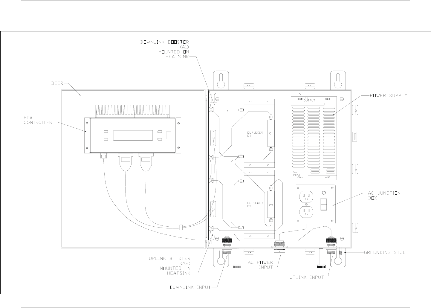
The BDA1300 consists of the following functions:
• 1 BDA Controller: Microprocessor based units that provides all control, fault
monitoring and settings for the BDA.
• 2 Duplexers D1, D2: Pass the Downlink frequency band to the mobile antenna and
the Uplink frequency band to the donor antenna and provide the isolation between
the Uplink and Downlink frequency bands.
• 2 Amplifiers A1, A2: Amplify the Uplink and Downlink signals.
• 2 Isolators C1, C2 (as required): Provide consistent matching for amplifier output.
• 1 Power Supply: Operates on 120/230VAC to provide 28V DC to amplifiers, BDA
Controller.
• BDA enclosure: Rugged Nema 4, 4x or 12 with heatsink attached to transfers heat
that dissipated from Amplifiers directly to the outside of the BDA enclosure.
• 1 AC Junction Box: This box consists of AC power switch, AC outlet and AC surge
protector.
BDA1300 Equipment Manual
DCM000000018 ©Kaval Telecom Inc. Page 3-7 of 51
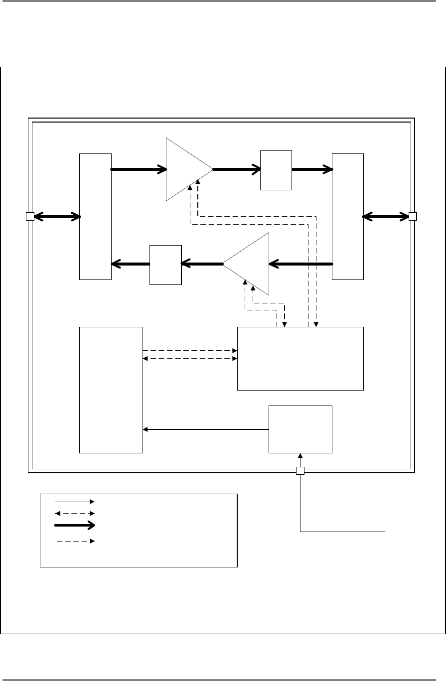
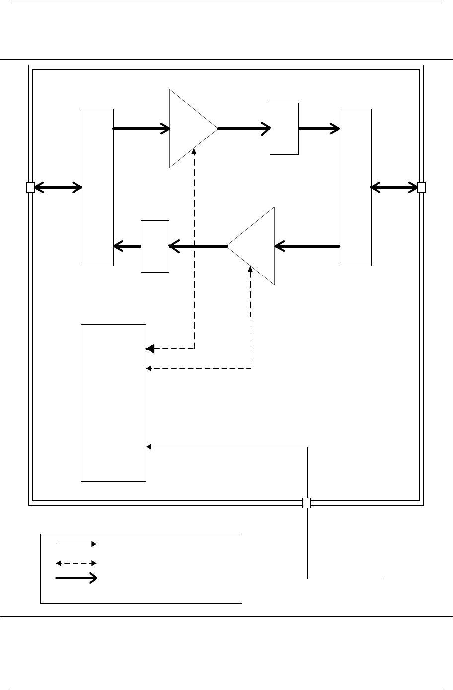
3.2 BDA1300 Block Diagram with Controller
D1 D2
DL
Booster
UL
Booster
DC
Power Supply
BDA Controller
AC
Junction Box
LEGEND
AC Power connection
DC Power connection
RF connection
Alarm & control connection
Donor
Mobile
AC -input
C1*
C2*
* C1, C2 will be added as required
BDA1300 Equipment Manual
DCM000000018
©Kaval Telecom Inc Page 9 of 51
3.3 BDA1300 Components in Enclosure with Controller
BDA1300 Equipment Manual
DCM000000018 ©
Kaval Telecom Inc Page 3-10 of 51
3.4 BDA1300 Block Diagram without Controller
D1 D2
DL
Booster
UL
Booster
DC
Power Supply
LEGEND
AC Power connection
DC Power connection
RF connection
Donor
Mobile
AC -input
C1*
C2*
*C1,C2 will be added as required
BDA1300 Equipment Manual
DCM000000018 ©Kaval Telecom Inc Page 3-11 of 51
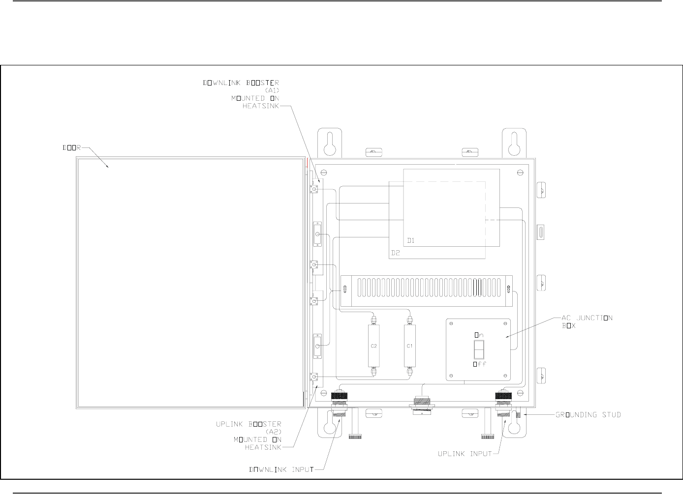
3.5 BDA1300 Components in Enclosure without Controller

BDA1300 Equipment Manual
DCM000000018 ©Kaval Telecom Inc Page 4-12 of 51
4 BDA1300 Models and Specifications
4.1 BDA1300 Specifications
RF Performance
Frequency Range 403 to 512 MHz
See model chart below
Passband Ripple ± 2.5 dB
Maximum Gain (nominal) 40 to 80 dB
See model chart below
Digital Gain Adjustment 16 or 32 dB
See model chart below
AGC Dynamic Range 25 dB
1 dB Compression Point +35 dBm Typical
3rd Order Intercept Point IP3 +45 dBm Typical
Noise Figure <12 dB
Propagation Delay <5 µs
Impedance 50 ohms
VSWR <2:1
Maximum RF Input +10 dBm without damage
Electrical Specifications
Primary Voltage 120/230VAC +/- 10%, 50-60Hz
Primary Power 180 VA
Secondary Power Two 12 VDC Sealed Lead -Acid Batteries, 10-100 AH
Battery Backup Time: Boosters only, 20 AH - 4 hrs Typical
Charge Time: 10 AH - Approx. 6 hrs, 100 AH - Approx. 48 hrs. Typical
Charge Current from BDA Controller is 3 Amps Maximum
The BDA will shut down for Battery Voltages below 21 VDC.
Consult Factory for more information.
Mechanical Characteristics
Dimensions W x H x D 17” x 16” x 10”
Weight 50 lbs. approx.
Housing Rugged Nema 4-Style Cabinet - Wall Mountable
Connectors N female
Operating Temperature Range -30°C to +50°C
Humidity 95% RH Max, Non-Condensing
Type Acceptance
FCC Type Acceptance H6M-BDA1300
IC Type Acceptance TBD

BDA1300 Equipment Manual
DCM000000018 ©Kaval Telecom Inc Page 4-13 of 51
4.2 BDA1300 Series Model Chart
Model Frequency (MHz) Maximum Gain IP3 (dBm)
DL UL (dB)
Digital Gain
Adjustment (dB) DL UL
BDA1300-xBB4-A TBD TBD 40 16 45 45
BDA1300-xBB7-A TBD TBD 70 32 45 45
BDA1300-xBB8-A TBD TBD 80 32 45 45

BDA1300 Equipment Manual
DCM000000018 ©Kaval Telecom Inc Page 4-14 of 51
4.3 Power De-Rating Requirements
BDA’s will amplify all signals that fall within their Pass-Band range. The output power will be “shared”
between all channels being amplified. Another multiple channel effect is Intermodulation signals
produced from non-linear effects between the intended channel signals. These intermodulation may
cause interference to receiving equipment.
In order to minimize Intermodulation signals, Power de-rating must be applied. In the USA there are
FCC Intermodulation Specifications published in the EIA Standard PN2009. The tables 2.2 shows the
maximum per channel Output Levels allowed as a function of the number of channel.
Note that depending on the actual amplifier input levels, the gain of the BDA may need to be reduced to
comply with the above regulations.
4.4 Automatic Gain Control (AGC)
Both Downlink and Uplink paths are equipped with AGC. The Amplifier based AGC has a dynamic
attenuation range that ensures that a field set (adjustable) nominal composite output power is not
exceeded. The AGC gain varies dynamically to maintain this composite power level by limiting strong
signal levels which could cause excessive intermodulation.
For example, if the AGC limit is set for +25 dBm and the gain of the unit is set for 40dB , then the AGC
circuit will begin to attenuate composite incoming signals at +25dBm – 40dBm = -15dB (composite
power input). The AGC circuit will maintain this composite power limit even if the input signals
increased. This composite level would be maintained by reducing the gain from 40 dB. For every 1dB
increase in input signal there would be a 1dB decrease in the gain.
The BDA Controller is used to set the AGC composite power threshold level. The AGC setting is a
value ranging from 0 to 255.
4.5 AGC Threshold level Setting
BDA’s may be shipped with an AGC setting chart specific to that unit.
This includes a 5 dB insertion loss for the internal Duplexers. Consult the Factory for more information.
The AGC Threshold level (in dBm) for the number of channels to be amplified is shown on the next
page. This AGC threshold should be set to ensure intermodulation products do not exceed –13dBm.
This table also shows the de-rated power per channel for the number of channels to be amplified.
BDA Controller
AGC Setting #
Composite Power Level
Setting
(+/- 1 dB)
240 +30 dBm
160 +25 dBm
118 +20 dBm
94 +15 dBm
77 +10 dBm

BDA1300 Equipment Manual
DCM000000018 ©Kaval Telecom Inc Page 4-15 of 51
4.6 BDA Per Channel Power De-Rating & AGC Threshold Setting
(for maximum level of 3rd order IMD products of –13 dBm)
No. of
Channels
Max. de-rated
Po/Channel, (dBm)
Composite Power
(dBm)
IP3=+45
2 25.4 28.4
3 22.6 27.4
4 20.7 26.7
5 19.2 26.2
6 18.0 25.8
7 17.0 25.5
8 16.2 25.2
9 15.4 24.9
10 14.7 24.7
11 14.1 24.5
12 13.6 24.4
13 13.1 24.2
14 12.6 24.1
15 12.2 24.0
16 11.8 23.8
17 11.4 23.7
18 11.1 23.6
19 10.7 23.5
20 10.4 23.4
21 10.1 23.4
22 9.8 23.3
23 9.6 23.2
24 9.3 23.1
25 9.1 23.1
26 8.8 23.0
27 8.6 22.9
28 8.4 22.9
29 8.2 22.8
30 8.0 22.8
31 7.8 22.7
32 7.6 22.7
64 3.6 21.7
Note: Above levels are established with AGC disabled. De-ratings are based
on values calculated using EIA standard PN2009. Actual Amplifier
performance may exceed the above criteria.

BDA1300 Equipment Manual
DCM000000018 ©Kaval Telecom Inc Page 5-16 of 51
5 BDA Enclosure Installation
5.1 Preparation for the installation of BDA enclosures
a. Equipment and hardware required
• Each BDA is carefully packaged for air shipment. Any damage incurred during the transportation must be
claimed from the shipper.
• Make sure the following necessary equipment and hardware are available and undamaged.
• 1 BDA enclosure (supplied by Kaval)
• 2 50-ohm jumper cables (not supplied by Kaval)
• 1 12’ AC power cord (not supplied by Kaval)
• AC Outlet is nearby (not supplied by Kaval)
• Padlocks, optional (not supplied by Kaval)
• Mounting hardware such as: Four washers and four bolts (not supplied by Kaval)
b. Preparing the installation site
• Make sure the mounting area is large enough to accommodate the installation of the BDA enclosure
(17”Wx16”Hx10”D) and free air flow is available on both sides of the cabinet.
• RF cables must be in place and labeled clearly as “Donor Cell Site” and “In-building”.
5.2 Mounting the BDA Enclosure
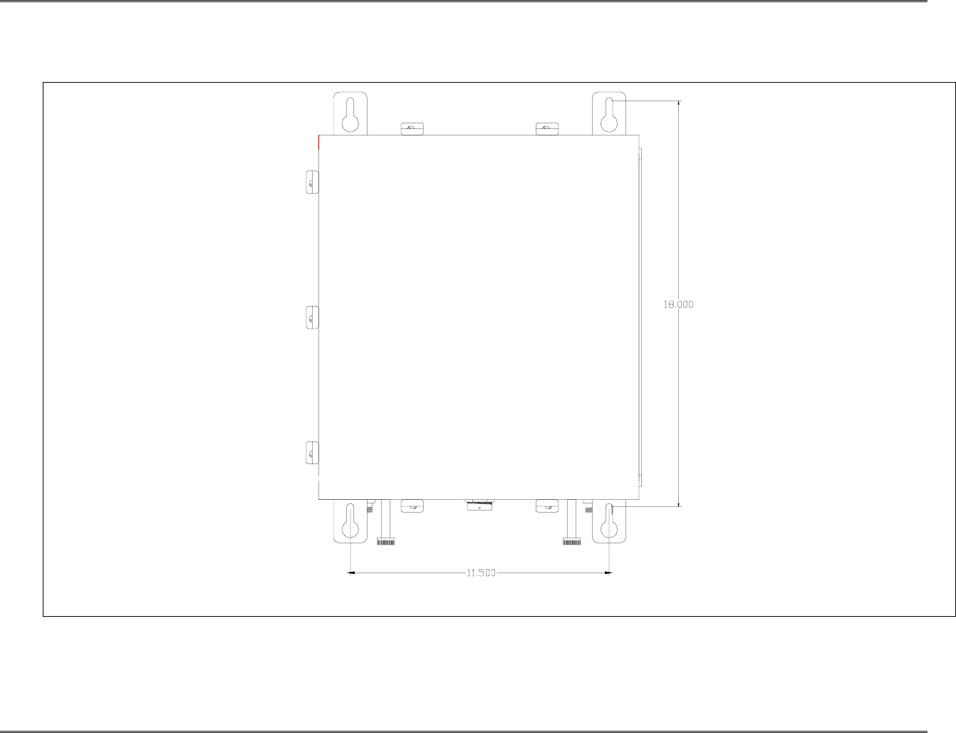
The physical installation is accomplished by mounting the enclosure onto a vertical wall. Ensure that the unit is
mounted in the upright position, as indicated by the upright Kaval logo and the door hinge on the left side of the
housing. Using four mounting lugs on the enclosure (see figure 3.1) as a template insert four bolts to the wall.
Make sure the bolts are capable of supporting at least 70 lbs. BDA Enclosure can be mounted as described
below:
1. Raise the BDA enclosure so that the BDA enclosure is about 1” to 3” away from the bolts so that one can
see the bolts through the larger diameter of the keyhole slots, see figure 3-1.
2. Move the BDA enclosure closer to the wall so those four keyhole type slots are hooked onto the bolts.
3. Slide the BDA enclosure down until all bolts fit well in the narrow part of the keyhole slots.
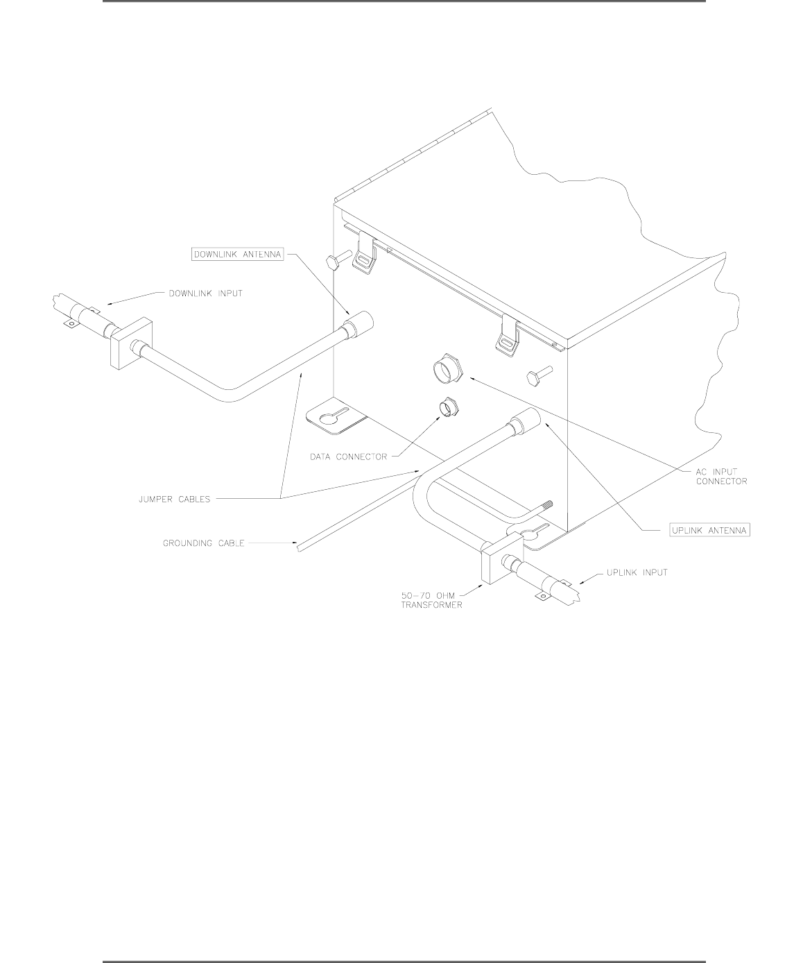
5.3 Connecting the Coaxial cables
Connectors of the BDA are located on the bottom of the BDA enclosure (see figure 3-2). RF cables can be
connected to these connectors using jumper cables as follows.
1. Connect one end of the first jumper cable to the BDA connector marked “Downlink Antenna.”
2. Connect the other end of the first jumper cable to the connector marked “Donor Cell Site” antenna.
3. Connect one end of the second jumper cable to the BDA connector marked “Uplink Antenna.”
4. Connect the other end of the second jumper cable to connector marked “In-building” cable.
BDA1300 Equipment Manual
DCM000000018
Kaval Telecom Inc. Page 5-21 of 51
5.4 BDA Enclosure Outline
BDA1300 Equipment Manual
DCM000000018
Kaval Telecom Inc. Page 22 of 51
5.5 RF and Power Connections

BDA1300 Equipment Manual
DCM000000018
Kaval Telecom Inc. Page 23 of 51
5.6 Connecting the Power Cables
AC Power and RF Connections should be installed with all standard installation practices for lightning
protection. This includes the grounding and electrical bonding together of all equipment racks and
cabinets in the room. It also includes a grounding of the primary antenna cable and the installation of
proper surge suppression (lightning arrestor) equipment at the entrance to the equipment room. It is
highly recommended that AC Power Wiring be performed by a qualified Electrician so as to ensure
compliance with all National and Local Electrical Wiring Regulations. Connecting power cables can be
done as follows:
1. Locate the AC on/off switch inside the BDA enclosure. Turn the switch to the OFF position.
2. The BDA enclosure can be grounded by connecting a No. 6 copper grounding wire to the
grounding stud located on the bottom of the BDA enclosure.
3. Connect the eight-pin connector on the power cable to the AC INPUT connector located on the
bottom of the BDA enclosure.
4. Turn the Power supply switch and the controller switch to the ON position. The light on the power
supply switch should be luminous and the controller display should say “BDA: OK”.
5. Set BDA operating parameters.
5.7 Securing the Door
The final step in installation BDA enclosure is to secure the door by fastening all the clamps and
attaching padlock as follows:
1. Close the door and fastening all seven clamps.
2. Attach padlock to BDA enclosure door as required.

BDA1300 Equipment Manual
DCM000000018
Kaval Telecom Inc. Page 24 of 51
6 Antenna Installation
! All Antenna Installation is to be performed by Qualified Technical Personnel only.
! Antenna Installation Instructions and locations below, are for the purpose of satisfying FCC
RF Exposure Compliance requirements.
! The Roof Top Antenna for linking to the Donor Site is a directional (high gain) Antenna fixed-
mounted physically on the side or top of a building, or on a tower. The Antenna Gain must be
no more than 10 dB. The Roof Top Antenna location should be such that only Qualified
Technical Personnel can access it, and that under normal operating conditions no other
person can touch the Antenna, or approach within 10 meters of the Antenna.
! The In-Building Antenna connection is via a coaxial cable distribution system with Signal
Taps at various points connected to the fixed-mounted Indoor Antennae. This is shown in the
figure in the Introduction. The Indoor Antennae are simple 1/4 Wavelength (0 dB Gain) types.
They are used with Kaval 12, 16, or 20 dB Cable Taps. As such the maximum EIRP will be at
the first Tapped Antenna, which will be 12 dB below the maximum signal level of the BDA1300
+25 dBm, or 0.32 Watts EIRP. These Antennae are to be installed such that no person can
touch the Antenna, or approach within 0.2 Meters.
ANTENNA INSTALLATION
WARNING
ALL ANTENNA INSTALLATION IS TO BE PERFORMED BY QUALIFIED TECHNICAL
PERSONNEL ONLY.
ANTENNA INSTALLATION INSTRUCTIONS AND LOCATIONS ARE FOR THE PURPOSE
OF SATISFYING FCC RF EXPOSURE COMPLIANCE REQUIREMENTS, AND ARE NOT
OPTIONAL.
ALL ROOF TOP ANTENNA INSTALLATION MUST BE SUCH THAT NO PERSON CAN
TOUCH THE ANTENNA, OR APPROACH CLOSER THAN 10 METERS.
ALL IN-BUILDING ANTENNAE INSTALLATIONS MUST BE SUCH THAT NO PERSON
CAN TOUCH THE ANTENNAE, OR APPROACH CLOSER THAN 0.2 METERS.
BDA1300 Equipment Manual
DCM000000018
Kaval Telecom Inc. Page 25 of 51
7 BDA Controller and Configuration
Kaval’s BDA’s can be configured very easily without the use of any tool via the BDA Controller. The
BDA must be powered up before setting the BDA operating parameters. The operating parameters are
set to specific defaults at the Kaval factory. All controller settings are recorded in the BDA Controller
Settings As-built list. The customer may also reset these parameters to optimize BDA performance in
the operating condition.
7.1 BDA1300 Controller Operation
The BDA Controller is a microprocessor based part of a Kaval BDA that provides password protected,
keypad entry of all system parameters including digital gain control, module fault monitoring, and
battery backup control. It interfaces to the 28 VDC Power Supply, the optional 24 VDC Battery (both
monitoring, transferring, and charging), control signals to the amplifiers, and provides monitored DC
power for the amplifiers.
The BDA Controller display is a 2 line by 20 character Vacuum Fluorescent (VFD) display. The
connectors are all secure lock type and should only be plugged and unplugged with power off.
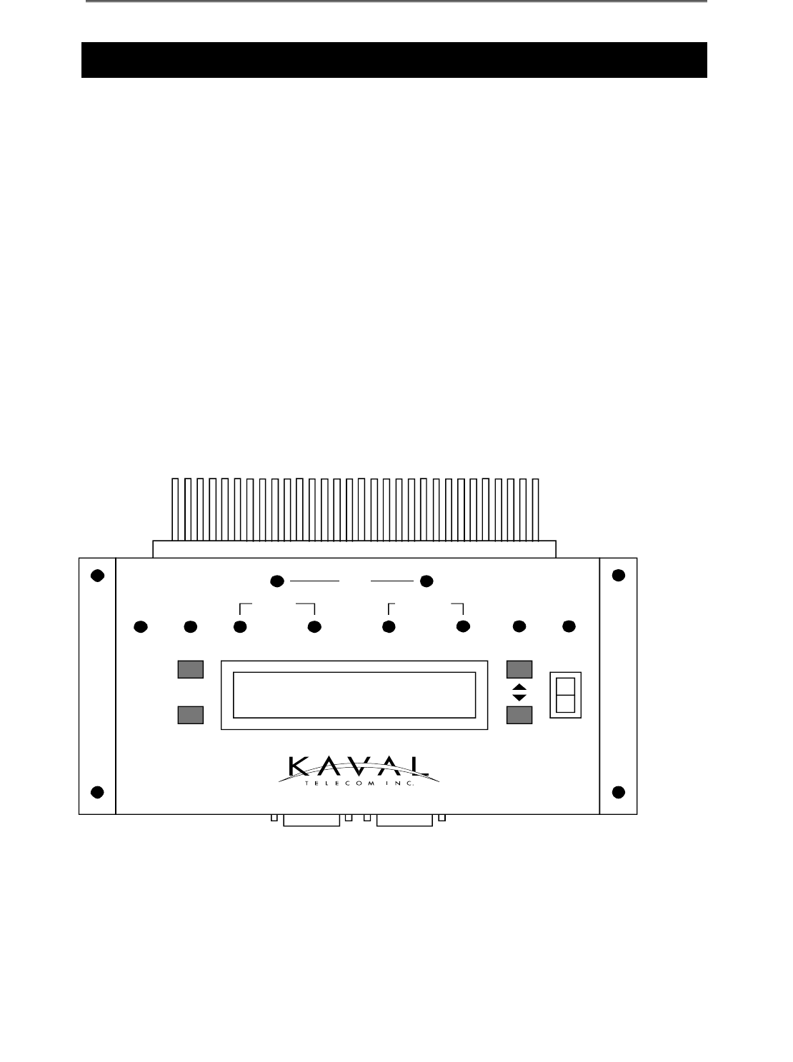
7.2 BDA Controller Drawing
BDA OK
BATT PA
AGC
BOOST PA
DOWNLINKUPLINK
BDA CONTROLLER
PWR FAIL TEMP FAN
ON
OFF
POWEREXIT
SELECT
ADJUST
BATT BOOST

BDA1300 Equipment Manual
DCM000000018
Kaval Telecom Inc. Page 26 of 51
7.3 BDA Controller User Interface
LED and Audible Indicators:
LED and audible indicators are used to enhance the user interface of the BDA. 10 LEDs
and buzzer are described below:
PWR FAIL Lights if primary power fails, and the system is on Battery Backup.
BATT Lights when the battery (if installed) voltage drops below 24 VDC which
roughly indicates 50% of backup capacity remaining. This may occur as
a result of normal discharge in a backup situation, battery exceeding its
useful life, or a battery failure such as water loss or shorted cell.
In addition, while running on battery backup, if the battery drops below 22
VDC, the LED will begin to blink indicating that self-shutdown is
imminent. If the battery drops below 21 VDC the BDA will shut down
completely to protect the Battery from damaging deep discharge.
UPLINK BOOST Lights if the Uplink Amplifier is enabled and has an overcurrent,
undercurrent, or internal fault.
UPLINK PA Lights if the Uplink PA (Power Amplifier) is enabled and has an
overcurrent, undercurrent, or internal fault.
DNLINK BOOST Lights if the Downlink Amplifier is enabled and has an overcurrent,
undercurrent, or internal fault.
DNLINK PA Lights if the Downlink PA is enabled and has an overcurrent,
undercurrent, or internal fault .
UPLINK AGC Lights to indicate that an Input Signal of sufficient strength is present to
cause the AGC circuit (if enabled) to act to reduce gain. The level at
which AGC action occurs is not a fixed signal level. It depends upon the
user setting for output level target. When lower targets are set, the AGC
will begin to act at lower input levels. When AGC is disabled, the LED
does nothing. If the Input Signal exceeds the AGC ability to reduce gain,
an overload condition exists, and the AGC LED blinks rapidly.
DNLINK AGC Operates the same as the Uplink AGC LED, but for the Downlink.
TEMP Lights when the BDA system temperature, as detected by a digital
sensor in the controller, exceeds the user programmed high temperature
threshold.
FAN Lights when the Cooling Fan(s) (if enabled) have an overcurrent or
undercurrent condition.
BUZZER The Buzzer sounds briefly during button presses for audible feedback.
When a User Function requires a confirmation, a short beep is emitted.
During a Fault Condition, a long periodic beep is sounded (this can be
disabled). When the Battery is about to be depleted when on Battery
Backup Power, the Buzzer will sound continuously.

BDA1300 Equipment Manual
DCM000000018
Kaval Telecom Inc. Page 27 of 51
Functions:
BDA system parameters can be set using the four button BDA controller keypad.
Description for the keypad buttons are listed below:
ON/OFF Power Switch for turning the BDA operation on and off. Note that this
only controls the BDA Controller, Amplifiers, PA’s, and Fans; the DC
Power Supply is still operating where BDA controller is switched off.
SELECT This Button is used to enter the Main Function Menu and Submenus,
and where applicable to confirm a Function selection chosen with the
Adjust Buttons.
EXIT This Button is used to cancel any Function changes, reverting to
previous settings. If a Fault has occurred and its Status is displayed,
pressing the Exit Button clears the fault.
ADJUST These buttons Scroll up and down between Status, Function, and Menu
display items. They also adjust programmable numeric values up and
down.
7.4 Checking BDA Status
Use ADJUST button to scroll through the Status menu such as Master status, current Monitor status
and Thermal Monitor Status. The controller should display “BDA OK” otherwise it would display “Fault!”
and the appropriate fault descriptions.
7.5 Setting BDA Operating Parameters
Before allowing the operator to change operating parameters, at the Main Menu, the controller will ask
the operator to enter a three-digit Password. The controller will skip the Password section if the field
password is set to ‘0000’ (disabled).
To enter the password, the operator uses the ADJUST button to scroll up or down for the desired
number, then depress the SELECT button to accept the number. The cursor will move to the next digit.
For the password to be valid, all three digits password must be entered correctly, one at a time, starting
from left to right.
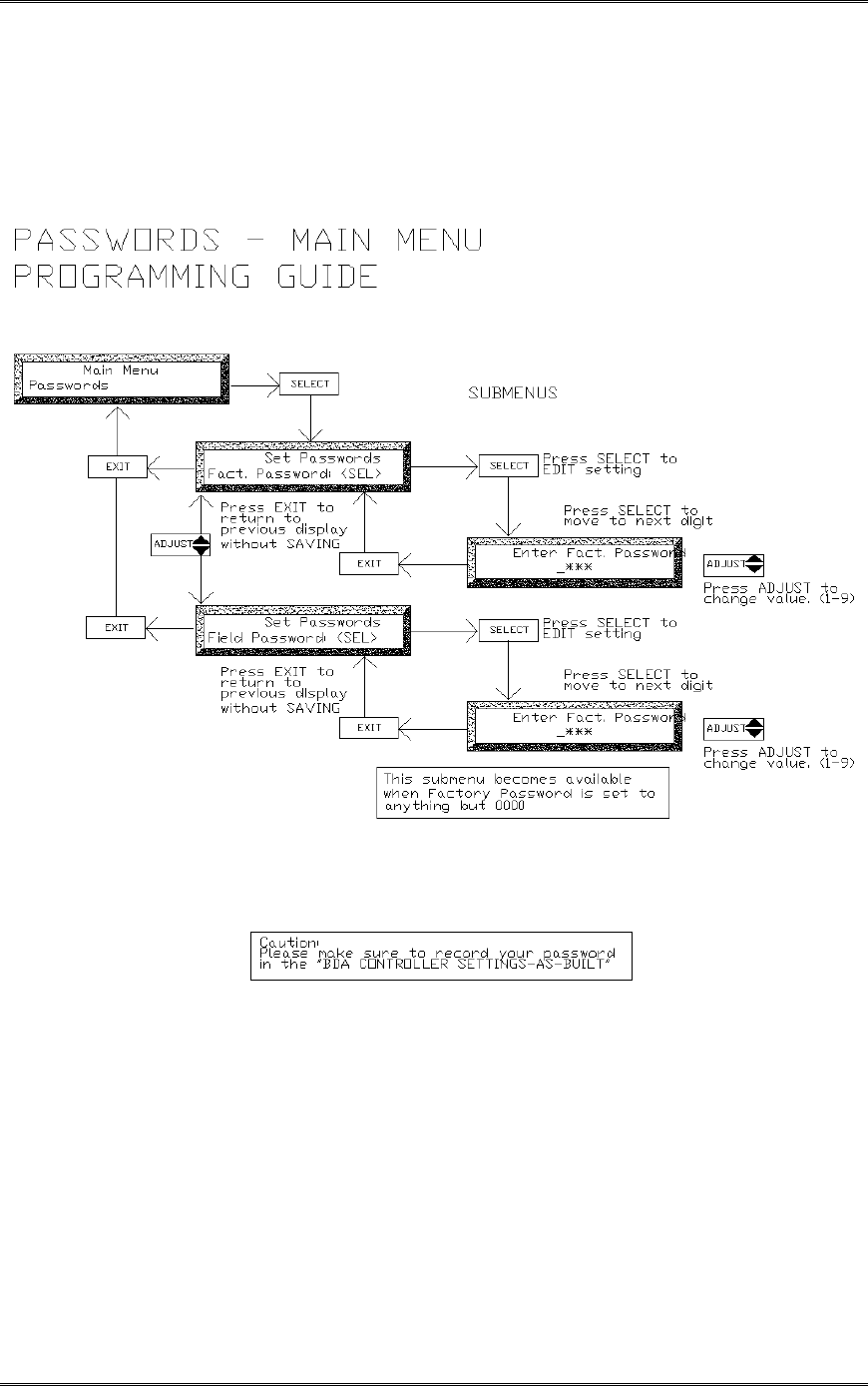
Note: Always write down the new password!
If BDA password is lost, the Network administrator must
contact Kaval to clear the Password.
BDA functions such as Gain, AGC, Battery, Temperature, Fans and Controller can be set through the
Menu. However, only certain parameters should be modified in the field. All other parameters have
been factory set based on the model configuration of the BDA and MUST NOT be modified. The chart
below shows the BDA parameters which may require modification in the field (based on each specific
BDA application).

BDA1300 Equipment Manual
DCM000000018
Kaval Telecom Inc. Page 28 of 51
CAUTION: The operator should not reset any other parameters.
To set these parameters please follow the programming guide for each parameter. The programming
guide shows the menus and key entries required to modify each parameter. The programming guides
for each parameter and an example are included at the end of this section.
Please note that it is recommended that any field-modified parameters be recorded on the “BDA
CONTROLLER SETTINGS - As-Built” sheet provided with the BDA. This As-built document should be
available for reference should the controller require replacement.
7.6 BDA Controller Field Settings Parameters
AS-Built
Reference
BDA Parameter Descriptions
1A Uplink Gain Set the overall Uplink gain of the BDA.
Refer to FIELD SETTINGS – MAIN MENU PROGRAMMING GUIDE
1B Downlink Gain Set the overall Downlink gain of the BDA.
Refer to FIELD SETTINGS – MAIN MENU PROGRAMMING GUIDE
1C Uplink AGC Set AGC based on number of channel for Uplink. The AGC setting is
from 0 to 255.
Refer to Table 2.1 for desired AGC level and FIELD SETTINGS – MAIN
MENU PROGRAMMING GUIDE to set AGC parameter value
1D Downlink AGC Set AGC based on number of channel for Downlink. The AGC setting is
from 0 to 255.
Refer to Table 2.1 for desired AGC level and FIELD SETTINGS – MAIN
MENU PROGRAMMING GUIDE to set AGC parameter value
1E Backup Power This parameter can be set to either SUPPLY or BATTERY.
Refer to FIELD SETTINGS – MAIN MENU PROGRAMMING GUIDE
1F Beep Audio indicator – not available on this model
2B Password New password can be set through the Controller main menu. If BDA
password is lost, contact network manager.
Refer to CONTROLLER – MAIN MENU PROGRAMMING GUIDE
8A Temp Shutdown If set to “Yes”, BDA will shutdown once the BDA reaches the
Temperature limit setting (not recommended in the Public safety
applications).
Refer to TEMPERATURE – MAIN MENU PROGRAMMING GUIDE
8B Temp Limit Alarm warning will issued once the BDA reach this Maximum operating
temperature setting.
Refer to TEMPERATURE – MAIN MENU PROGRAMMING GUIDE
8C Recovery Temp
After shutting itself down, BDA will turn back on when it reaches this
recovery temperature setting.
Refer to TEMPERATURE – MAIN MENU PROGRAMMING GUIDE

BDA1300 Equipment Manual
DCM000000018
Kaval Telecom Inc. Page 29 of 51
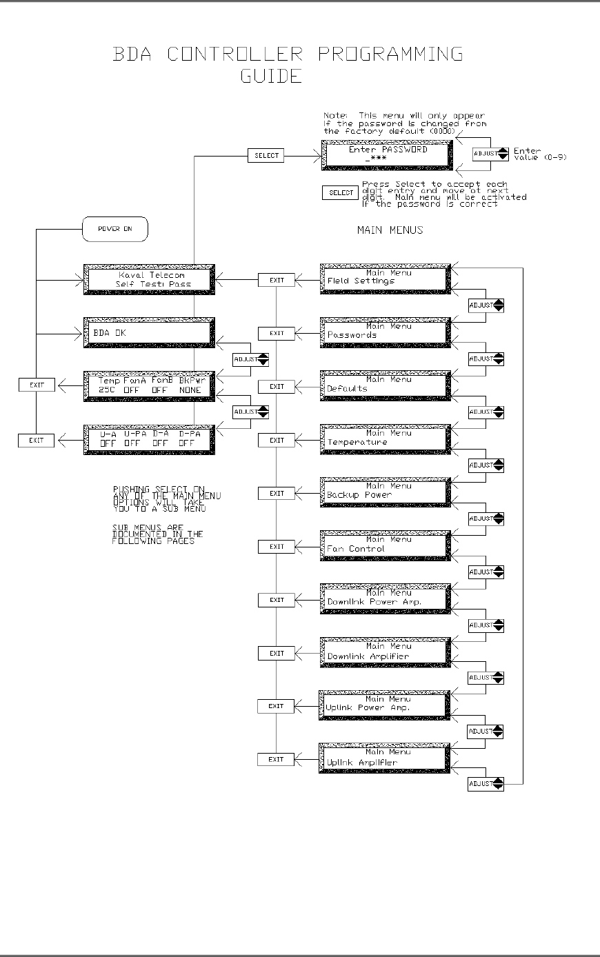
7.7 BDA Controller Configuration Guide
NOTE: Refer to the CONFIGURATION GUIDE diagrams at the end of this
section to navigate throughout all menus.
There are four levels of displays in the BDA controller:
• Level 1 - Status menus
• Level 2 - Main menus
• Level 3,4 - Submenus
Status Menus
When the BDA is first turned on, the controller performs a self-diagnostic check. If the unit passes this
test, “PASS” will be momentarily displayed, which then changes to “BDA OK” as shown below.
BDA OK
This display is always present under normal operating conditions.
The BDA Controller has 2 other status displays, which can be viewed by pressing the Adjust
Buttons. The screens are:
1. Amplifier Current Monitor Status
2. Temperature, Fan, and Backup Power Status
Amplifier Current Monitor Status
This Screen displays the current drawn by each Amplifier and PA in the system. The top row
shows abbreviated names for the amplifiers as follows:
U-A is the abbreviation for Uplink Amplifier
U-PA is the abbreviation for Uplink Power amplifier
D-A is the abbreviation for Downlink Amplifier
D-PA is the abbreviation for Downlink Power amplifier
The bottom row shows the current being drawn by each amplifier (in Amps) or the status of the
amplifier. Each amplifier will display one of 4 possible statuses as follows:
X.XX – Current consumption (in Amps) of amplifier (displayed under normal operation
conditions)
OVER - Displayed if amplifier is consuming excessive current
Undr - Displayed if amplifier is consuming insufficient current
NONE - Displayed if amplifier has not been program installed
The display below shows a sample CURRENT MONITOR STATUS
U-A U-PA D-A D-PA
0.65 Over 0.65 Off
Temperature, Fan, and Backup Power Status
This Screen shows the current ambient temperature of the BDA, the status of Fan A &B, and the
status of the Backup Power (if installed). Temperature readout is in degrees Celsius. If an over-
temperature condition exists, temperature will flash. Each fan has an indication of On, Off or Fail.

BDA1300 Equipment Manual
DCM000000018
Kaval Telecom Inc. Page 30 of 51
Backup Power voltage is displayed in volts to a resolution of 10 mV. If Backup Power is not
installed, display says “None”.
Temp FanA FanB BkPWR
53C ON Fail None
Fault Conditions
When a Fault occurs, the associated fault LED will light and the display will show a text message
identifying the specific fault(s) condition.
The display below shows a sample fault for an amplifier drawing excessive current. The fault
LED for the associated amplifier is also lit.
Fault!
Overtemperature
The following list shows all possible fault displays:
Main Up Amp. Overcur Up PA Overcurrent
Back Up Amp. Overcur Dn PA Overcurrent
Main Dn Amp. Overcur Up PA Undercurrent
Back Dn Amp. Overcur Dn PA Undercurr
Main Dn Amp. Undrcur Fan A Fail
Back Dn Amp. Undrcur Fan B Fail
Main Dn Amp. Undrcur Overtemperature
Back Dn Amp. Undrcur Imminent Shutdown
Backup Power Low Primary Power Fail
Main Menus
The Main Menu is entered by pressing the Select Button from any Status Display. If the Field
Password is set to anything but ‘0000’ (default), then a Password Entry Screen appears. The
Adjust Buttons are used to scroll to the desired password digit value. Pressing SELECT will enter
the digit and move the cursor to the next digit. When the third digit is entered, and the Password
is correct, the Main Menu becomes available and is displayed. If an incorrect Password is
entered, then the message “Wrong Password” appears for a few seconds and the user must start
again. If the Password is set to 0000 (disabled) the Main Menu is available immediately. The
display below shows the password entry dialog.
Enter PASSWORD
4***
Main Menu entries are used to group Functions by category. The User SELECTS the desired
category and a submenu appears listing available Functions. While in the Main Menu, the top row
of the display shows “Main Menu”, and the bottom row shows the Main menu name (e.g., “Field
Settings”). The main menu categories are accessed by scrolling up or down using the ADJUST
buttons. When the desired main menu category is displayed, pressing SELECT will access the
submenus within the main menu category. When in the submenu the first row of the displays the
main menu category name (e.g., “Field Settings”) and the bottom row displays the submenu
name (e.g., “SYSTEM LOSS: XdB”). The following list shows all available MAIN MENUS

BDA1300 Equipment Manual
DCM000000018
Kaval Telecom Inc. Page 31 of 51
MAIN MENUS
Field Settings
Passwords
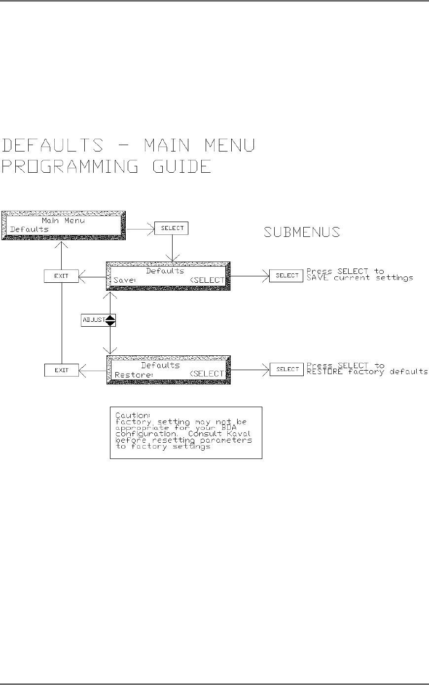
Defaults
Temperature
Backup Power
Fan Control
Downlink Power Amp.
Downlink Amplifier
Uplink Power Amp.
Uplink Amplifier
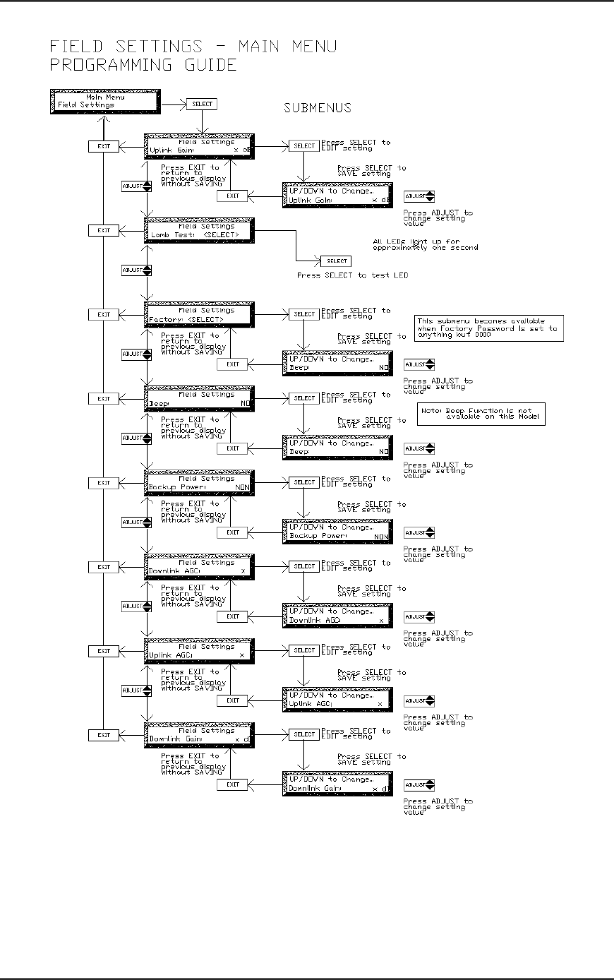
Field Settings Main Menu
The Field Settings main menu allows adjustment of the following submenu items:
Uplink Gain
Downlink Gain
Uplink AGC
Downlink AGC
Backup Power
Beep
Lamp Test
Factory (display only when the factory password is set)
Passwords Main Menu
This Menu allows the factory password settings. Once the password is set to anything but 0000
(default), only the Field Settings main menu is available for adjustment. A password submenu
called Factory will be available in the Field Settings. User will have access to all the main menus
when a correct Factory password is entered.
A second password level called Field Password will be available once the factory password is set
to anything but 0000 (default). When this Field Password is set to anything but 0000 (disabled),
user cannot access any Main Menu without entering the correct Field Password.
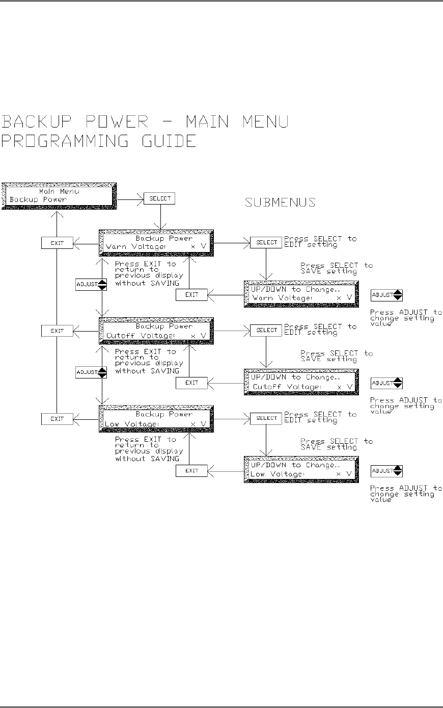
Backup Power Main Menu
This Menu allows the user to configure the BDA for backup power functionality.
If a battery is select in the Field Settings as backup power then this main menu category must be
programmed as follows:
Low Voltage: 24.0 (indicates voltage at which Warning is displayed)
Warn Voltage: 21.5 (voltage level at which imminent BDA shutdown is displayed as an
alarm)
Cutoff Voltage: 21.0 (voltage level at which battery back up is discontinued to prevent
battery damage)
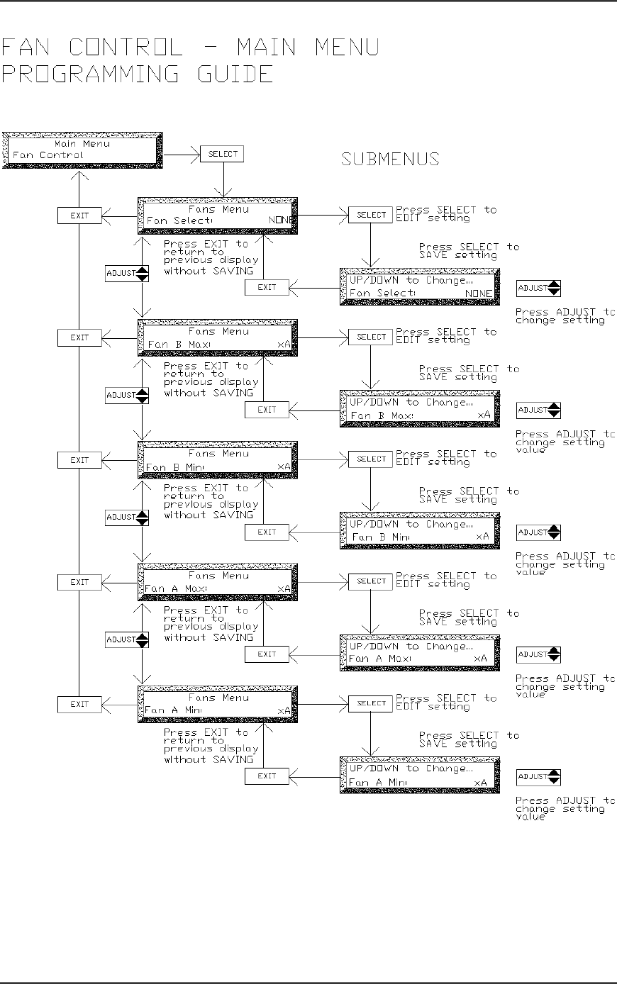
Fan Control Main Menu
This menu has been programmed by the factory, based on the BDA configuration and
should not be accessed or modified.
This menu is used to configure the BDA cooling fans (if installed). Entry submenus include:
Fan Select: selects BDA fan configuration (available entries are NONE, A, B, BOTH)
Fan B min: indicates Fan B minimum operating current
Fan B max: indicates Fan B maximum operating current
Fan A min: indicates Fan A minimum operating current
Fan A max: indicates Fan A maximum operating current
If Fan A is selected then Fan B functions as a hot-switchover backup for Fan A

BDA1300 Equipment Manual
DCM000000018
Kaval Telecom Inc. Page 32 of 51
If an overtemperature condition occurs, then both fans will engage until the temperature drops
below a pre-set recovery limit.
If BOTH are selected then both fans operate under normal conditions
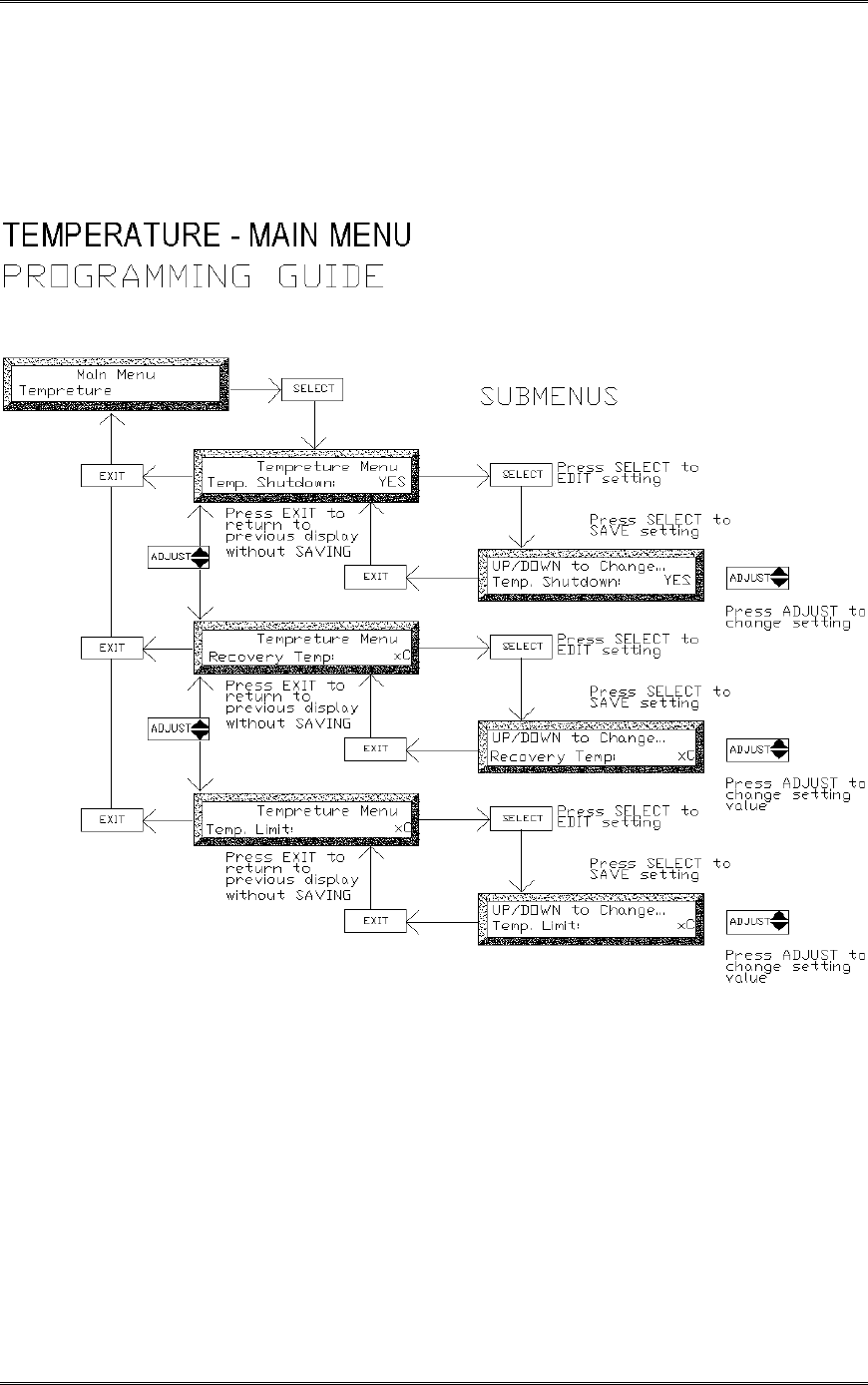
Temperature Main Menu
This menu allows the user to define the acceptable operating temperature of the BDA. Note that
the BDA will operate normally in temperatures of –30 C to + 50C (ambient temperature external
to BDA), however, the user may wish to monitor the ambient temperature inside the BDA as an
indicator of external conditions and take appropriate action if the temperature rises above a
preset limit. The menu setting include:
Temp Limit: 60C (indicates the temperature at which the BDA will shut itself down)
Recovery Temp: 40C (indicates the temperature at which the BDA will re-start itself)
Temp Shutdown: Yes (enables automatic BDA shutdown if temp. limit, is exceeded)
If an over-temperature condition occurs and FANS are installed and enabled, then both fans will
engage until the temperature drops below a pre-set recovery temperature limit.
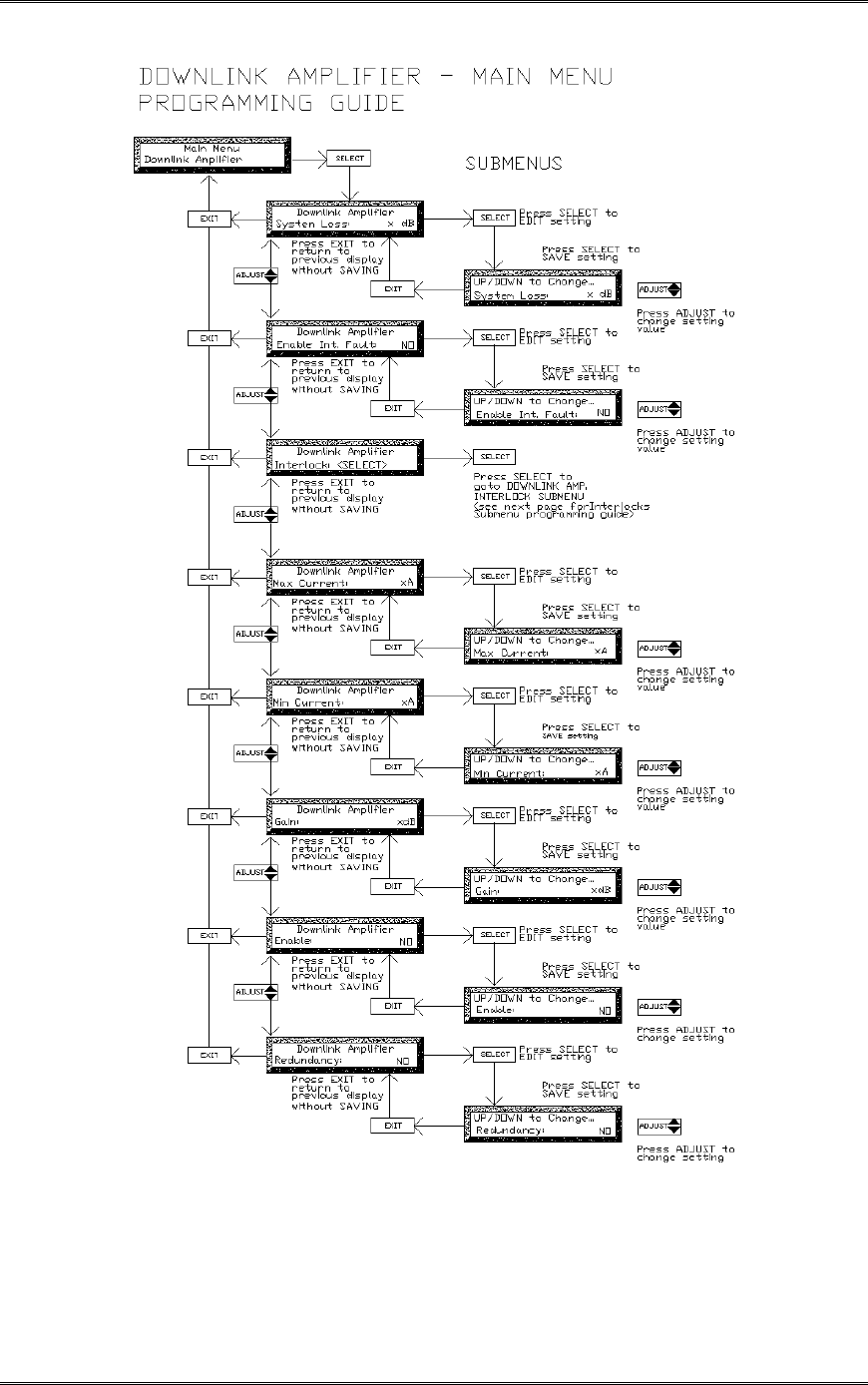
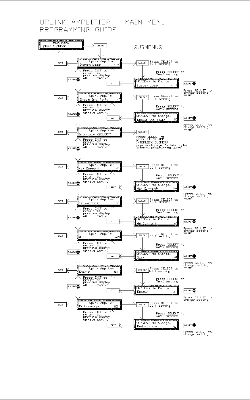
Uplink & Downlink Amplifier Main Menus
These menus have been programmed by the factory, based on the BDA configuration and
should not be accessed or modified.
Submenu entries include:
System Loss: (indicates insertion loss of the duplexers)
Enable Int Fault: (not used)
Interlock (indicates action to be taken by other amplifiers if this amplifier fails)
Min Current (indicates minimum normal operating current in Amps)
Max Current: (indicates maximum normal operating current in Amps)
Gain: (indicates amplifier max gain configuration in dB)
Enable: (enables/disables amplifier)
Redundancy: (enables/disables power stage redundancy feature)
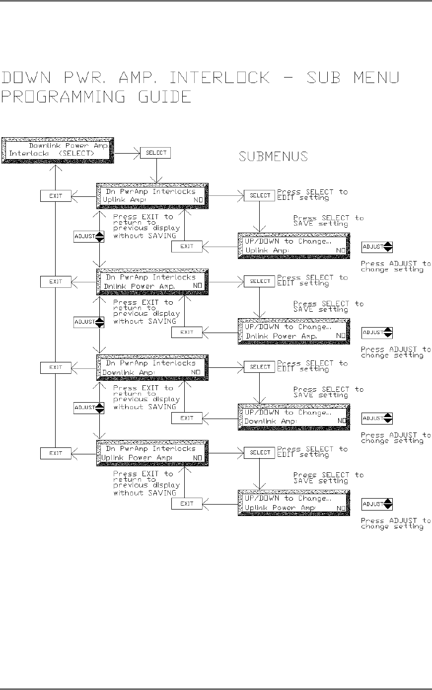
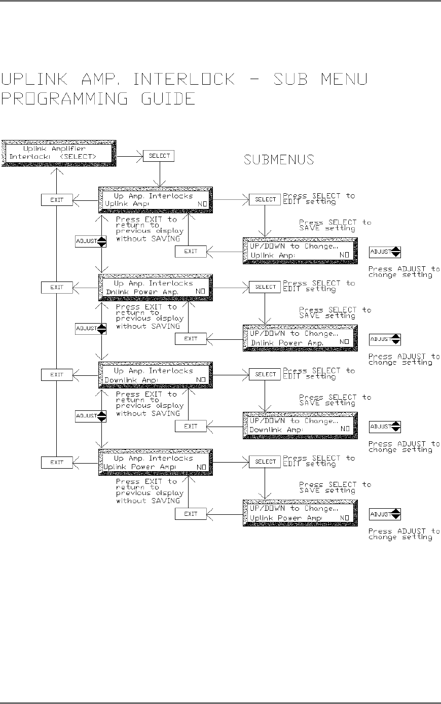
Interlock Submenu
The Interlock entry, if selected, calls up another submenu that allows the user to select what
modules are disabled if the Amplifier has a fault. This submenu includes:
Uplink Amplifier: (disables amplifier in event that the subject amplifier has a fault)
Downlink PA: (disables amplifier in event that the subject amplifier has a fault)
Downlink Amplifier: (disables amplifier in event that the subject amplifier has a fault)
Uplink PA: (disables amplifier in event that the subject amplifier has a fault)
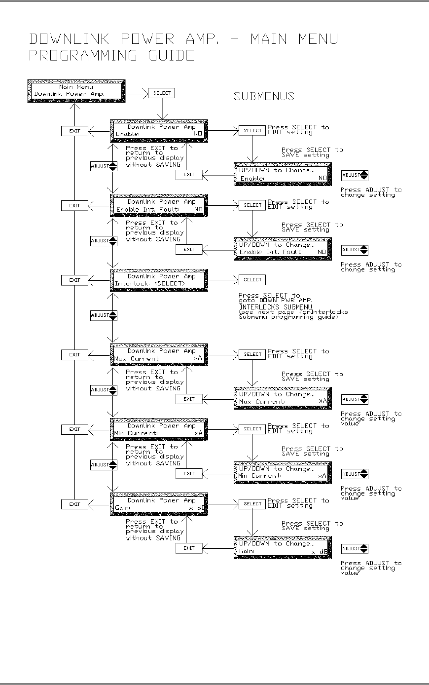
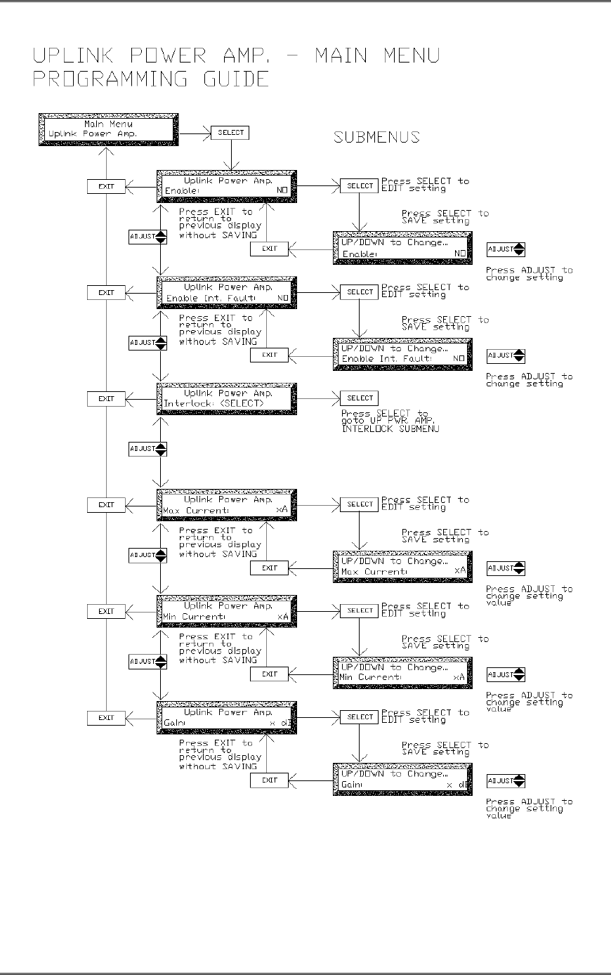
Uplink and Downlink Power Amp. Main Menus
These menus have been programmed by the factory, based on the BDA configuration and
should not be accessed or modified.
Submenu entries include:
Enable: (enables/disables amplifier)
Enable Int Fault: (not used)
Interlock (indicates action to be taken by other amplifiers if this amplifier fails)
Max Current: (indicates maximum normal operating current in Amps)
Min Current (indicates minimum normal operating current in Amps)
Gain: (indicates amplifier max gain configuration in dB)
BDA1300 Equipment Manual
DCM000000018
Kaval Telecom Inc. Page 33 of 51
BDA1300 Equipment Manual
DCM000000018
Kaval Telecom Inc. Page 34 of 51
BDA1300 Equipment Manual
DCM000000018
Kaval Telecom Inc. Page 35 of 51
BDA1300 Equipment Manual
DCM000000018
Kaval Telecom Inc. Page 36 of 51
BDA1300 Equipment Manual
DCM000000018
Kaval Telecom Inc. Page 37 of 51
BDA1300 Equipment Manual
DCM000000018
Kaval Telecom Inc. Page 38 of 51
BDA1300 Equipment Manual
DCM000000018
Kaval Telecom Inc. Page 39 of 51
BDA1300 Equipment Manual
DCM000000018
Kaval Telecom Inc. Page 40 of 51
BDA1300 Equipment Manual
DCM000000018
Kaval Telecom Inc. Page 41 of 51
BDA1300 Equipment Manual
DCM000000018
Kaval Telecom Inc. Page 42 of 51

BDA1300 Equipment Manual
DCM000000018
Kaval Telecom Inc. Page 43 of 51
BDA1300 Equipment Manual
DCM000000018
Kaval Telecom Inc. Page 44 of 51

BDA1300 Equipment Manual
DCM000000018
Kaval Telecom Inc. Page 45 of 51
BDA1300 Equipment Manual
DCM000000018
Kaval Telecom Inc. Page 46 of 51
BDA1300 Equipment Manual
DCM000000018
Kaval Telecom Inc. Page 47 of 51

BDA1300 Equipment Manual
DCM000000018
Kaval Telecom Inc. Page 48 of 51
7.8 Example - Setting the Downlink Gain
Below is an example of setting the BDA Downlink Gain. Setting for other parameters can be done
in a similar fashion.
1. From Master Status press SELECT to get to the Field Settings Menu. The controller will
ask for the password if the field password was not 0000 (disabled). Use the ADJUST
button to select a digit and presses the SELECT button to enter that digit and move to the
next digit. The controller will display the Field Settings Main Menu once all three digits
were entered correctly.
2. Press SELECT to get into Field Settings submenu, displaying the first entry: “Uplink Gain”
.
3. Use the ADJUST the " button to scroll up to “Downlink Gain”.
4. Press SELECT to edit this parameter.
5. Use ADJUST " # to change the “Downlink Gain” to the desired x dB value. Then
press SELECT to SAVE the change, or press the Exit button to exit edit mode without
changing the Downlink Gain value.
When all adjustments are completed in the Field Settings submenu, use EXIT to go back to the Field
Settings Main Menu and then Master Menu.

BDA1300 Equipment Manual
DCM000000018
Kaval Telecom Inc. Page 49 of 51
8 Troubleshooting and Maintenance
8.1 Maintenance & Safety
The BDA has been engineered for easy maintenance and for safe operation. This has been
achieved as follows :
!BDA Controller provides fault monitoring and accurate status report through LED.
! The 28V DC Power-supply is over-rated for actual requirements.
! Boosters are monitored for both Over-current and Under-current (most failures are sensed
this way).
!Cabinet temperature is monitored for excessive temperature.
!Components are easily removable via quick connect DC and RF connectors.
8.2 Maintenance Philosophy
Field maintenance should require a screwdriver, a multi-meter, spares of each of the active
BDA component parts, and a Portable Radio to monitor off the air signals. There is no
requirement to have any test equipment to accomplish most service repairs.
! All BDA component parts have been designed for reliable long life operation.
! The BDA Controller performs ongoing extensive built in diagnostics.
! Corrective action can often be taken without detailed technical knowledge or the need for
any test equipment.
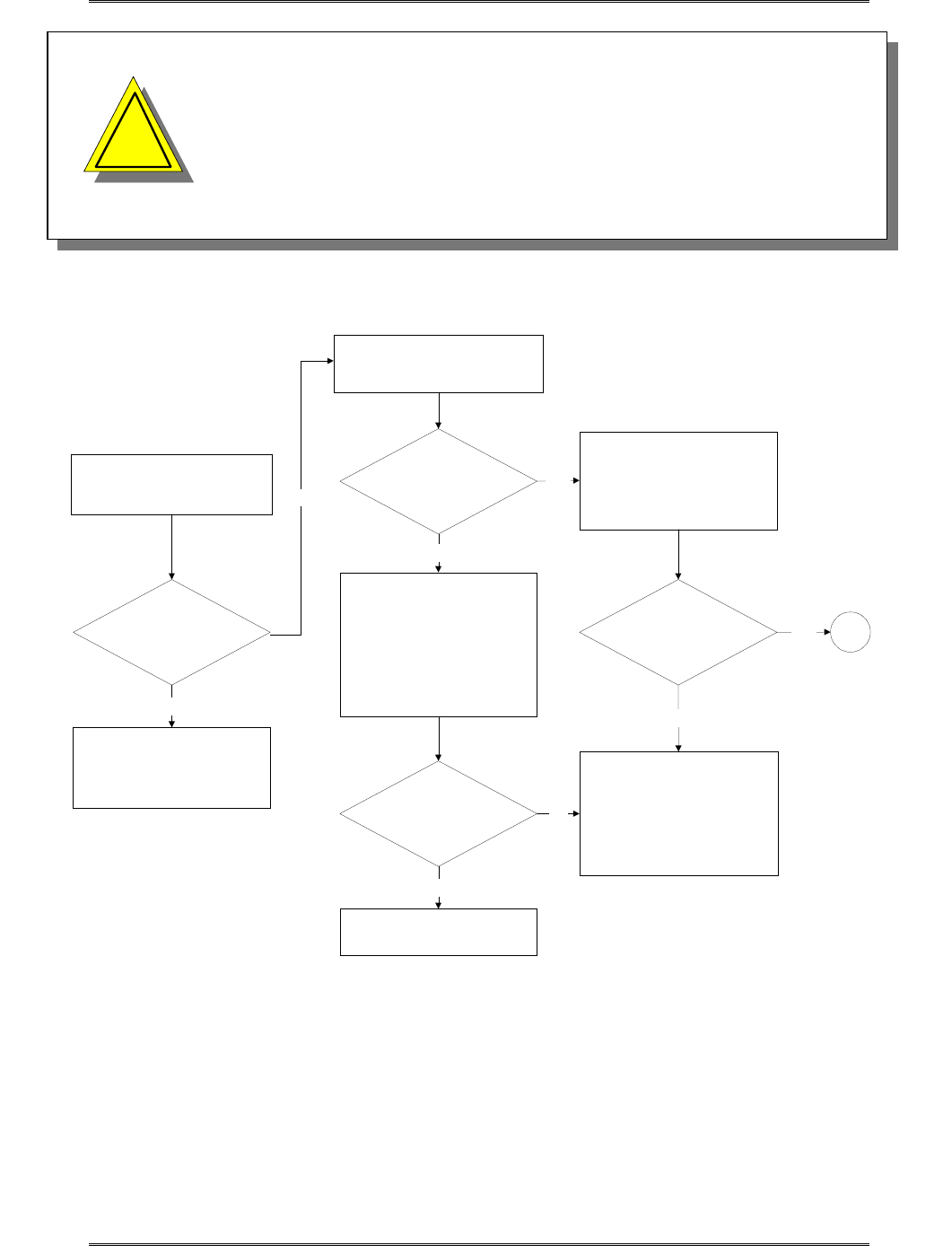
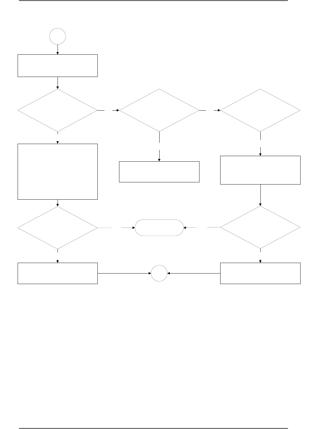
8.3 Troubleshooting Procedure
1. Before attempting to troubleshoot the BDA, you should study the troubleshooting flowchart
carefully.
2. Always observe personal and equipment safety practices during troubleshooting.
3. Follow each step of the troubleshooting flowchart to check for the fault and to replace the
recommended component.
4. Recommended Test Equipment:
• Multimeter
• Test cables, SMA adapter
• Spare components for substitution.
• Phillips screwdrivers
BDA1300 Equipment Manual
DCM000000018
Kaval Telecom Inc. Page 50 of 51
•
Note: If you are not familiar with electronic system
troubleshooting, Please contact Kaval at 1-888-86-KAVAL
for assistance or ask for a RMA (Return Material
Authorization) before sending BDA unit to an authorized
service agent
Donor Site &
Portable Radio
Equipment perform
satisfactory?
No
Open BDA door and check BDA
Controller Display
Status Display
is lit?
1. Reset the AC circuit breaker.
2. Turn AC power switch off,
wait for 1 minute then turn it on
again to clear DC power supply
internal thermal fuse that has
tripped.
3. Turn Power switch of BDA
controller off and on again.
AC power
and /or Battery backup
power (if present)
has been lost?
Status LEDs
are lit?
No
Yes
Yes
Replace BDA Controller
Note:
the new Controller should be
programmed with the same
settings as that of the existing
controller prior to replacement.
1
Yes
Start
Troubleshooting Procedure
Fix or Optimize Donor Site
and / or Portable Radio
Equipment
Check the AC Installation
Yes
No
1. Turn Power switch of BDA
controller off and on Again.
2. Check for approximately 28
VDC from the BDA DC power
supply.
No
TROUBLESHOOTING FLOWCHART
!
!
BDA1300 Equipment Manual
DCM000000018
Kaval Telecom Inc. Page 51 of 51
Check Fault Status on:
PA, Booster, Fans,
Power supply and Battery
Replace the Faulty
Component specified by BDA
Controller
1
1. Power and/ or control wiring
to that component has been
disconnected or broken.
Suspected broken or faulty
cables should be disconnected
and reconnected to see if the
Fault clears.
2. Clear all Faults.
Under Current ?
The Fault clears?
Yes
Replace the Faulty
Component
Yes
Replace over-heating
component or any failed cooling
Fans
1. Make sure any ventilation
openings are not blocked.
2. Clear all Faults.
The Fault clears?
Yes
No
No
Yes
End
Troubleshooting
Yes
1
TROUBLESHOOTING FLOWCHART
(Continued)
Over Current ? Over-temperature ?No
No

BDA1300 Equipment Manual
DCM000000018
Kaval Telecom Inc. Page 52 of 51
9 STANDARD WARRANTY
Products manufactured by Kaval Telecom Inc. are warranted to be free under
normal use and service from defect in workmanship or materials for a period of
one year from the date of shipment to the original purchaser. This warranty
supersedes and voids any and all other warranties expressed or implied.
In no event shall Kaval Telecom Inc. be liable for incidental or consequential
damages arising from the use, misuse, failure to operate or improper operation of
any Kaval product or product accessory.
Specifically excluded from this warranty is any claim of merchantability or fitness
for a particular purpose or application.
This warranty is void if the product has been subject to misuse, neglect,
accidental damage, damage of a cosmetic nature, misapplication, extreme
environmental conditions, unauthorized repair or alteration.
Customer must contact Kaval Telecom before shipping a product for warranty
services to obtain a Returned Material Authorization. Shipping charges for
returned products must be PREPAID. A return shipping fee will be charged if a
returned item is found by Kaval not to be defective or defective for a reason that
voids the warranty.

BDA1300 Equipment Manual
DCM000000018
Kaval Telecom Inc. Page 53 of 51
10 Product Service Procedure
Return and Repair Procedures
The BDA can be returned for repair by the following procedures:
• Contact Kaval Telecom Inc. at 1888-86-KAVAL for a Return Materials
Authorization (RMA) number. Please provide serial number and model
number.
• Ship the defective part prepaid in the original shipping box to:
Kaval Telecom Inc.
ATTN: Returned Part ; RMA number:XXXX
60 Gough Road
Markham, On
L3R 8X7
Canada

BDA1300 Equipment Manual
DCM000000018
Kaval Telecom Inc. Page 54 of 51
11 Ordering Parts and Accessories
Parts ordering information
Parts and accessories for the BDA may be purchased by contacting Kaval Telecom
Inc. at 1888-86-KAVAL for prices and delivery. When ordering a replacement part,
please provide model number, serial number and software version number (See
BDA Controller Settings-“As-Built” list).

BDA1300 Equipment Manual
DCM000000018
Kaval Telecom Inc. Page 55 of 51
12 Glossary
AGC Automatic gain control is an RF output limiter that protects against
damage from oscillations and prevents excessive intermodulation
distortion.
Amplifier A class A amplifier. BDA cabinet contains four amplifiers, two for the
uplink/downlink path of A-band and two for the uplink/downlink path of B-
band.
Downlink Also called the forward path. In this path, the RF signal is transmitted
by the donor cell then received, amplified and re-radiated by distribution
system to the portable/mobile radio equipment
Interlock BDA controller function that allows the user to select (from Amplifier or
PA menu) which modules are to be disabled in the even that component
(Amplifier or PA) has a fault.
Line Amplifier Bi-directional amplifier that provides amplifications of RF signals to
recover signal loss contributed by system components such as radiating
cable, splitter and so on.
PA Power Amplifier. To increase power, some BDA cabinet contains two PA,
one for the uplink path and one for the downlink path.
Uplink Also called the reverse path. In this path, the RF signal is transmitted by
the portable/mobile radio equipment then received, amplified and re-
radiated by the distribution system to the donor cell.