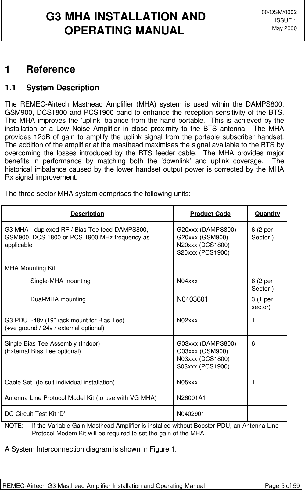
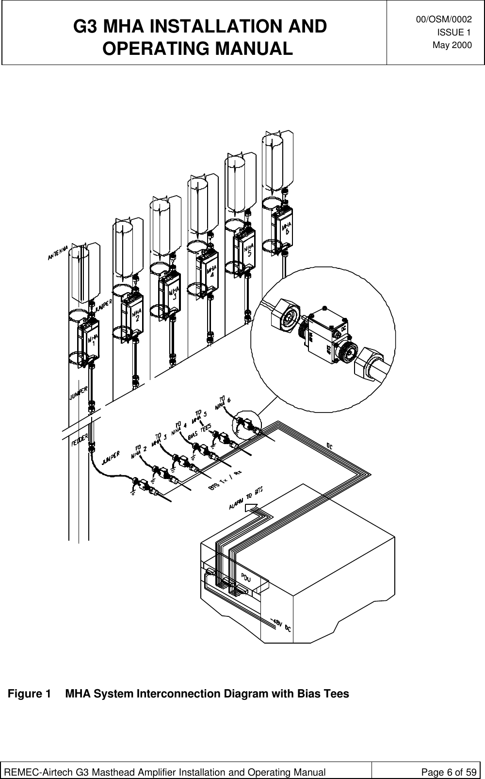
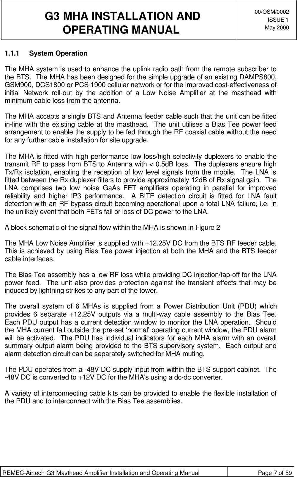
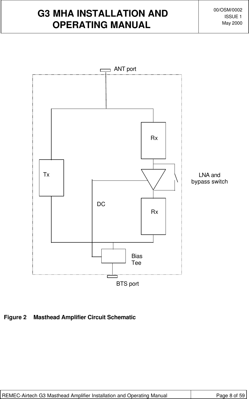
Powerwave Technologies G20034A1 Cellular Band Repeater User Manual 00OSM0002 1

Powerwave Technologies, Inc. Cellular Band Repeater 00OSM0002 1

Manual

  G3 MHA INSTALLATION ANDOPERATING MANUAL00/OSM/0002ISSUE 1May 2000REMEC-Airtech G3 Masthead Amplifier Installation and Operating Manual Page 1 of 59G3 MASTHEAD AMPLIFIERINSTALLATION AND OPERATINGMANUALThe information contained in this document is furnished in commercial confidence and upon the conditionthat the individual and corporate rights originating in the information, whether patented or not, will berespected.Reference: 00/OSM/0002 Issue: 1 Date: May 2000Prepared by:Ranjit S MankuAuthorised by Engineering: Authorised by Quality:
 G3 MHA INSTALLATION ANDOPERATING MANUAL00/OSM/0002ISSUE 1May 2000REMEC-Airtech G3 Masthead Amplifier Installation and Operating Manual Page 2 of 59HISTORYDATE ISSUE AUTHOR MOD/ISSUENOTE NOTES18/05/00 1Ranjit S Manku ECO 1262 First Issue
 G3 MHA INSTALLATION ANDOPERATING MANUAL00/OSM/0002ISSUE 1May 2000REMEC-Airtech G3 Masthead Amplifier Installation and Operating Manual Page 3 of 59CONTENTS1Reference....................................................................................................................................................51.1 System Description.......................................................................................................................51.1.1 System Operation..............................................................................................................71.1.2 Interfaces ............................................................................................................................91.2 Hardware Description................................................................................................................ 201.2.1 Masthead Amplifier ........................................................................................................ 201.2.2 Power Distribution Unit................................................................................................. 201.2.3 Bias Tee........................................................................................................................... 211.2.4 Cable Kit........................................................................................................................... 211.2.5 MHA Mounting Kit............................................................................................................ 212Installation Manual................................................................................................................................. 222.1 General......................................................................................................................................... 221.1.1 Recommended RF Cable Installation Components .............................................. 231.1.2 Installation Summary and Mounting Configuration ................................................. 231.2 Installation of Masthead Amplifier (MHA) ............................................................................... 261.2.1 General Mounting Instructions..................................................................................... 261.1.2 Detailed MHA Installation Procedure.......................................................................... 271.1.3 Installation of Bias Tee.................................................................................................. 331.1.4 Installation of Power Distribution Unit........................................................................ 331.1.5 Installation of Cables..................................................................................................... 342.3 Grounding Cables and Lightning Protection......................................................................... 342.3.1 Clamping of cables and correct Grounding.............................................................. 342.3.2 Ground Path Requirements ......................................................................................... 342.3.3 Grounding/Earthing of the MHA................................................................................... 342.3.4 Schematic of Lightning Protection circuit................................................................... 352.3.5 Basic Grounding/Earthing: Good Practice................................................................. 352.4 Installation Measurements ....................................................................................................... 362.4.1 A Method of measurement of Static Gain of the MHA.............................................. 362.4.2 Effects of Cable Length on the Noise Figure............................................................ 372.4.3 The effects of introducing REMEC-Airtech G3 MHA................................................. 372.4.4 The Effect of Auxiliary attenuator in the Rx path ........................................................ 383Operation and Maintenance ................................................................................................................ 403.1.1 Set-up and Test.............................................................................................................. 403.1.2 Fault Finding and Repair Procedures ........................................................................ 403.1.3 MHA to Ground Equipment DC circuit Test............................................................... 424Variable Gain MHA Option .................................................................................................................... 494.1 Hardware Description................................................................................................................ 494.1.1 Variable Gain Masthead Amplifier............................................................................... 494.1.2 Power Distribution Unit................................................................................................. 504.1.3 Bias Tee........................................................................................................................... 504.1.4 Cable Kit........................................................................................................................... 504.1.5 Mounting Kit..................................................................................................................... 514.1.6 Antenna Line Protocol Modem Kit............................................................................... 514.2 Installation of Variable Gain MHA............................................................................................ 524.3 Operation and Maintenance of Variable Gain MHA.............................................................. 524.3.1 Gain Setting of the Variable Gain MHA....................................................................... 525Frequently Asked Questions ............................................................................................................... 555.1 Lightning Protection Circuit....................................................................................................... 555.2 Mounting and Maintenance....................................................................................................... 586Glossary.................................................................................................................................................... 59
 G3 MHA INSTALLATION ANDOPERATING MANUAL00/OSM/0002ISSUE 1May 2000REMEC-Airtech G3 Masthead Amplifier Installation and Operating Manual Page 4 of 59Table of FiguresFigure 1  MHA System Interconnection Diagram with Bias Tees............................................... 6Figure 2 Masthead Amplifier Circuit Schematic...................................................................... 8Figure 3 Masthead Amplifier Interfaces.................................................................................. 9Figure 4 Power Distribution Unit Interfaces (Indoor)................................................................12Figure 5 Power Distribution Unit Interfaces (Outdoor).............................................................13Figure 6 Bias Tee Cable Kit for Outdoor PDU........................................................................15Figure 7 Bias Tee Interfaces................................................................................................16Figure 8 PDU DC Output port to Bias Tee ............................................................................17Figure 9 PDU Alarm port to BTS Alarm................................................................................18Figure 10 Mounting Bracket Kits...........................................................................................19Figure 11 G3 MHA - Typical Mounting Configuration................................................................25Figure 12 Flat Surface and Pole Mounting of a Single MHA .....................................................27Figure 13 Flat Surface or Pole Mounting of Stacked Dual MHAs ..............................................28Figure 14  Installation of the MHA using a Single-MHA Mounting Bracket kit.............................31Figure 15 Interface Drawing of G3 MHAs................................................................................32Figure 16 A Schematic of a Lightning Protection Circuit ..........................................................35Figure 17  DC Circuit Test Kit ‘D’...........................................................................................43Figure 18 Test Kit Configuration during confidence test............................................................44Figure 19 Flow Chart 1 ~ Test Kit D confidence test................................................................45Figure 20 Operating Current Test for a System without Bias Tee or BTS ...................................46Figure 21 Operating Current Test for a System with a Bias Tee but without a BTS .....................47Figure 22 Operating Current Test for a System with a Bias Tee and BTS connected ..................48Figure 23 Antenna Line Protocol Modem................................................................................51Figure 24 MHA Management Terminal Window on Laptop PC..................................................53Figure 25 MHA Gain Adjustment using ALP Modem and Laptop PC.........................................54
 G3 MHA INSTALLATION ANDOPERATING MANUAL00/OSM/0002ISSUE 1May 2000REMEC-Airtech G3 Masthead Amplifier Installation and Operating Manual Page 5 of 591 Reference1.1 System DescriptionThe REMEC-Airtech Masthead Amplifier (MHA) system is used within the DAMPS800,GSM900, DCS1800 and PCS1900 band to enhance the reception sensitivity of the BTS.The MHA improves the ‘uplink’ balance from the hand portable.  This is achieved by theinstallation of a Low Noise Amplifier in close proximity to the BTS antenna.  The MHAprovides 12dB of gain to amplify the uplink signal from the portable subscriber handset.The addition of the amplifier at the masthead maximises the signal available to the BTS byovercoming the losses introduced by the BTS feeder cable.  The MHA provides majorbenefits in performance by matching both the 'downlink' and uplink coverage.  Thehistorical imbalance caused by the lower handset output power is corrected by the MHARx signal improvement.The three sector MHA system comprises the following units:Description Product Code QuantityG3 MHA - duplexed RF / Bias Tee feed DAMPS800,GSM900, DCS 1800 or PCS 1900 MHz frequency asapplicableG20xxx (DAMPS800)G20xxx (GSM900)N20xxx (DCS1800)S20xxx (PCS1900)6 (2 perSector )MHA Mounting KitSingle-MHA mounting N04xxx 6 (2 perSector )Dual-MHA mounting N0403601 3 (1 persector)G3 PDU  -48v (19” rack mount for Bias Tee)(+ve ground / 24v / external optional) N02xxx 1Single Bias Tee Assembly (Indoor)(External Bias Tee optional) G03xxx (DAMPS800)G03xxx (GSM900)N03xxx (DCS1800)S03xxx (PCS1900)6Cable Set  (to suit individual installation) N05xxx 1Antenna Line Protocol Model Kit (to use with VG MHA) N26001A1DC Circuit Test Kit ‘D’ N0402901NOTE:  If the Variable Gain Masthead Amplifier is installed without Booster PDU, an Antenna LineProtocol Modem Kit will be required to set the gain of the MHA.A System Interconnection diagram is shown in Figure 1.
 G3 MHA INSTALLATION ANDOPERATING MANUAL00/OSM/0002ISSUE 1May 2000REMEC-Airtech G3 Masthead Amplifier Installation and Operating Manual Page 6 of 59Figure 1 MHA System Interconnection Diagram with Bias Tees
 G3 MHA INSTALLATION ANDOPERATING MANUAL00/OSM/0002ISSUE 1May 2000REMEC-Airtech G3 Masthead Amplifier Installation and Operating Manual Page 7 of 591.1.1 System OperationThe MHA system is used to enhance the uplink radio path from the remote subscriber tothe BTS.  The MHA has been designed for the simple upgrade of an existing DAMPS800,GSM900, DCS1800 or PCS 1900 cellular network or for the improved cost-effectiveness ofinitial Network roll-out by the addition of a Low Noise Amplifier at the masthead withminimum cable loss from the antenna.The MHA accepts a single BTS and Antenna feeder cable such that the unit can be fittedin-line with the existing cable at the masthead.  The unit utilises a Bias Tee power feedarrangement to enable the supply to be fed through the RF coaxial cable without the needfor any further cable installation for site upgrade.The MHA is fitted with high performance low loss/high selectivity duplexers to enable thetransmit RF to pass from BTS to Antenna with < 0.5dB loss.  The duplexers ensure highTx/Rx isolation, enabling the reception of low level signals from the mobile.  The LNA isfitted between the Rx duplexer filters to provide approximately 12dB of Rx signal gain.  TheLNA comprises two low noise GaAs FET amplifiers operating in parallel for improvedreliability and higher IP3 performance.  A BITE detection circuit is fitted for LNA faultdetection with an RF bypass circuit becoming operational upon a total LNA failure, i.e. inthe unlikely event that both FETs fail or loss of DC power to the LNA.A block schematic of the signal flow within the MHA is shown in Figure 2The MHA Low Noise Amplifier is supplied with +12.25V DC from the BTS RF feeder cable.This is achieved by using Bias Tee power injection at both the MHA and the BTS feedercable interfaces.The Bias Tee assembly has a low RF loss while providing DC injection/tap-off for the LNApower feed.  The unit also provides protection against the transient effects that may beinduced by lightning strikes to any part of the tower.The overall system of 6 MHAs is supplied from a Power Distribution Unit (PDU) whichprovides 6 separate +12.25V outputs via a multi-way cable assembly to the Bias Tee.Each PDU output has a current detection window to monitor the LNA operation.  Shouldthe MHA current fall outside the pre-set ‘normal’ operating current window, the PDU alarmwill be activated.  The PDU has individual indicators for each MHA alarm with an overallsummary output alarm being provided to the BTS supervisory system.  Each output andalarm detection circuit can be separately switched for MHA muting.The PDU operates from a -48V DC supply input from within the BTS support cabinet.  The-48V DC is converted to +12V DC for the MHA's using a dc-dc converter.A variety of interconnecting cable kits can be provided to enable the flexible installation ofthe PDU and to interconnect with the Bias Tee assemblies.
 G3 MHA INSTALLATION ANDOPERATING MANUAL00/OSM/0002ISSUE 1May 2000REMEC-Airtech G3 Masthead Amplifier Installation and Operating Manual Page 8 of 59Figure 2Masthead Amplifier Circuit SchematicANT portRxTx LNA andbypass switchRxBTS portDC      Bias      Tee
 G3 MHA INSTALLATION ANDOPERATING MANUAL00/OSM/0002ISSUE 1May 2000REMEC-Airtech G3 Masthead Amplifier Installation and Operating Manual Page 9 of 591.1.2 Interfaces1.1.2.1 Masthead AmplifierThe MHA is provided with the following electrical interfaces (refer to Figure 3):a) 7/16 Female (BTS):  This is the connection for the duplexed Tx/Rx signals to/from theBTS.  In addition to providing for RF transmission, this connector provides for DC feedvia the RF cable and Bias Tee assembly. b) 7/16 Female (ANT):  This is the connection for the Tx/Rx Antenna.  This port should beas close as possible to the antenna with the connection being made with theshortest/lowest loss interconnecting cable practicable. c) M8 Earth Stud:  This provides the Primary Lightning protection earth for the MHA.  Theearth cable should be of the largest cross sectional area and shortest lengthpracticable and should be connected to a suitable earth point on the mast structure.Figure 3Masthead Amplifier Interfaces7/16 FEMALE (BTS)M8 EARTH STUD7/16 FEMALE (ANT)
 G3 MHA INSTALLATION ANDOPERATING MANUAL00/OSM/0002ISSUE 1May 2000REMEC-Airtech G3 Masthead Amplifier Installation and Operating Manual Page 10 of 591.1.2.2 Power Distribution UnitNote: The PDU is not required where DC power to the MHAs and Alarm functions areprovided directly from the BTS.In a standard system configuration, an indoor PDU is used.  Details of the indoor PDUinterfaces are given below.  A brief description of the outdoor PDU interfaces is alsoincluded in this section.Indoor PDUThe PDU is provided with the following electrical interfaces (refer to Figure 4):a) DC power input connector type SLA 4/90 3.2 SN:  This connector is provided for theprimary -48V DC input from the BTS supply and is wired as follows:  Pin Number Function  1No Connection 2Equipment Ground 3Primary supply return 4-48V Primary Supply Feed  b) +12V DC Output connector type 'DB9S' 9 pole Female:  This connector provides the 6individually switched DC outputs to the Bias Tee for onward coaxial supply to the MHAand is wired as follows:  Pin Number Function  1MHA No. 1 +12V DC Supply Output 2MHA No. 2 +12V DC Supply Output 3MHA No. 3 +12V DC Supply Output 4MHA No. 4 +12V DC Supply Output 5MHA No. 5 +12V DC Supply Output 6MHA No. 6 +12V DC Supply Output 70v DC return 80v DC return 9No connection
 G3 MHA INSTALLATION ANDOPERATING MANUAL00/OSM/0002ISSUE 1May 2000REMEC-Airtech G3 Masthead Amplifier Installation and Operating Manual Page 11 of 59  c) Alarm Output connector type 'DB9P' 9 pole Male:  This connector provides the Sectorand DC>DC Alarm Output and is wired as follows: Pin Number Function1Sector 1 Alarm.2Sector 2 Alarm.3Sector 3 Alarm.4DC - DC Alarm.50V Ground.6Sector 1 Alarm.7Sector 2 Alarm.8Sector 3 Alarm.9DC - DC Alarm.d)  M6 Earth Stud. Provides the Primary Lightning protection earth to the PDU.  The earthcable should be of the largest cross sectional area and of minimum length practicableto provide maximum lightning protection.
 G3 MHA INSTALLATION ANDOPERATING MANUAL00/OSM/0002ISSUE 1May 2000REMEC-Airtech G3 Masthead Amplifier Installation and Operating Manual Page 12 of 59Figure 4Power Distribution Unit Interfaces (Indoor)
 G3 MHA INSTALLATION ANDOPERATING MANUAL00/OSM/0002ISSUE 1May 2000REMEC-Airtech G3 Masthead Amplifier Installation and Operating Manual Page 13 of 59Outdoor PDUThe indoor compact PDU in housed inside a weatherproof enclosure to provide anOutdoor PDU.  Additional lightning protection is included within the enclosure.  Details ofthe outdoor PDU interfaces are shown in Figure 5Figure 5Power Distribution Unit Interfaces (Outdoor)
 G3 MHA INSTALLATION ANDOPERATING MANUAL00/OSM/0002ISSUE 1May 2000REMEC-Airtech G3 Masthead Amplifier Installation and Operating Manual Page 14 of 59Outdoor PDU is provided with the following electrical interfaces:a) DC power input connector type SLA 4/90 3.2 SN:  This connector in on the compactPDU unit inside the outdoor enclosure and is provided for the primary -48V DC inputfrom the BTS supply.  An input cable is passed through the grommet (DC input) on theenclosure panel and is wired as follows:  Pin Number Function  1No Connection 2Equipment Ground 3Primary supply return4 -48V Primary Supply Feedb) +12V DC Output connections to the Outdoor Bias Tees are provided using six cableswith ‘Binder’ connectors (one for each Bias Tee) shown in Figure 6.  The cables arepassed through six ‘Bias Tee Feed’ grommets on the enclosure panel.  PINconnections on the connector block inside the enclosure are as follows:  Number on Block Function  1(+,-) MHA No. 1 +12V DC Supply Output and return 2(+,-) MHA No. 2 +12V DC Supply Output and return 3(+,-) MHA No. 3 +12V DC Supply Output and return 4(+.-) MHA No. 4 +12V DC Supply Output and return 5(+,-) MHA No. 5 +12V DC Supply Output and return 6(+,-) MHA No. 6 +12V DC Supply Output and return c) BTS Alarm Output connector type '8 pin Metalok Bantam’ on the enclosure panel.This connector provides the Sector and DC>DC Alarm Output and is wired as follows: Pin Number FunctionA and B Summary Sector Alarm.C and D DC – DC AlarmSecond ‘8 pin Metalok Bantam’ connector (EXT Alarm) in normally not used.
 G3 MHA INSTALLATION ANDOPERATING MANUAL00/OSM/0002ISSUE 1May 2000REMEC-Airtech G3 Masthead Amplifier Installation and Operating Manual Page 15 of 59  Figure 6Bias Tee Cable Kit for Outdoor PDU1.1.2.3 Bias TeeThe Bias Tee is provided with the following electrical interfaces (refer to Figure 7):a) DIN 7/16 Female (BTS):  This is the connection for the duplexed Tx/Rx signals to/fromthe BTS. b) DIN 7/16 Male (ANT):  This is the RF output connection to the Antenna feeder cable.As well as providing for RF transmission, this connector provides for DC feed via theRF cable to the MHA. c) PDU Input connector (type SMB Male for indoor Bias Tee, Binder for outdoor BiasTee):  This connector provides the DC supply input to the Bias Tee for onward supplyto the MHA and it is wired as follows:  Pin Number Function  Inner Bias Tee +12V DC supply Input. Outer Bias Tee DC return. d) M6 Earth Stud: Provides the Primary Lightning protection earth to the Bias Tee.  Theearth cable should be of the largest cross sectional area and of the minimum lengthpracticable to provide maximum lightning protection.
 G3 MHA INSTALLATION ANDOPERATING MANUAL00/OSM/0002ISSUE 1May 2000REMEC-Airtech G3 Masthead Amplifier Installation and Operating Manual Page 16 of 59Indoor Bias TeeOutdoor Bias TeeFigure 7Bias Tee InterfacesNote: Alternative connector genders are available to suit cable interfaces.
 G3 MHA INSTALLATION ANDOPERATING MANUAL00/OSM/0002ISSUE 1May 2000REMEC-Airtech G3 Masthead Amplifier Installation and Operating Manual Page 17 of 591.1.2.4 Cable Kit using indoor PDU and Bias TeesThe cable kit comprises the necessary cables and interfaces to enable the interconnectionof the PDU and Bias Tee units within the BTS cabinet.The relevant product code is N0500XXX (XXX depends on BTS type) for a BTS usingquantity 6 off Bias Tees.a) PDU Output port to Bias Tee (refer to Figure 8)  This cable comprises six individual screened coaxial cables with a 9 pole 90o free 'D'type plug for connection to the PDU DC output socket. The six individual tails areterminated with an SMB free socket for attachment to each of the 6 Single Bias TeeDC inputs.                         Figure 8PDU DC Output port to Bias Tee
 G3 MHA INSTALLATION ANDOPERATING MANUAL00/OSM/0002ISSUE 1May 2000REMEC-Airtech G3 Masthead Amplifier Installation and Operating Manual Page 18 of 59  b) PDU Alarm to BTS Alarm port (refer to Figure 9)  This is an 8 conductor cable with a 9 pole 90o free 'D' type socket for connection to thePDU Alarm output socket.  The other end is un-terminated to enable installerconnection to the alarm concentrator PCB in the BTS cabinet. Figure 9PDU Alarm port to BTS Alarm1.1.2.5 MHA Mounting KitThe mounting kit comprises the brackets, fitted to both ends of the MHA, straps for polemounted configuration and bolts for wall mounted configuration.  There are two types ofmounting bracket kits, Single-MHA mounting and Dual-MHA mounting as shown in Figure10.
 G3 MHA INSTALLATION ANDOPERATING MANUAL00/OSM/0002ISSUE 1May 2000REMEC-Airtech G3 Masthead Amplifier Installation and Operating Manual Page 19 of 59Single MHA Mounting KitDual MHA Mounting KitFigure 10 Mounting Bracket Kits
 G3 MHA INSTALLATION ANDOPERATING MANUAL00/OSM/0002ISSUE 1May 2000REMEC-Airtech G3 Masthead Amplifier Installation and Operating Manual Page 20 of 591.2 Hardware Description1.2.1 Masthead AmplifierThe MHA comprises a tower top mounted enclosure which is provided with fixing suitablefor wall or pole mounting.  The enclosure is sealed to provide IP68 protection of the internalcomponents.  The MHA is based upon a triplexer filter design with an integrated Low NoiseAmplifier and Bias Tee assembly.  The whole internal module is formed from a single silverplated assembly to provide best in class insertion loss performance.The triplexer filters are arranged to provide a Low Loss transmit path by the use of abandpass filter between the BTS and Antenna ports.  Each of the external ports includesan internal diplexing junction to connect 2 off bandpass filters to the Tx filter.The Rx bandpass filter connected to the Antenna port provides pre-selection of Rx signalsand protection from the high power transmitter signals.  The Rx filter is connected to a LowNoise Amplifier with approximately 12dB gain.The LNA comprises a Quadrature coupled pair of GaAs FETs to improve IP3 high levelperformance and reliability.  The LNA contains internal BITE detection circuitry to indicatefailure of either FET and to signal a fault condition to the PDU within the BTS.  In theunlikely event that both FETs fail, the bypass circuit switches the LNA out of line.  Theoutput of the LNA is then connected via a second Rx bandpass filter to the BTS port of theMHA.A Bias Tee assembly is fitted at the BTS port diplexer junction to enable a coaxial DC feedfrom the BTS to be fed off to the LNA.  The Bias Tee assembly contains DC blocking in theRF path and RF blocking in the DC path.  The unit has integral Lightning Protection toprovide clamping of any lightning induced voltages which could damage the LNA circuitry.1.2.2 Power Distribution UnitThe MHA system is supplied with +12V DC from a Power Distribution Unit (PDU) whichprovides 6 separate outputs at to each MHA from an input supply of -48V DC (otheroptions also available) derived from the BTS BBU.  The conversion of the input at -48V toa +12V output voltage is achieved by a dc-dc converter system. The PDU supply inputhas transient and reverse power protection to prevent damage to the dc-dc assemblies.The outputs of the dc-dc assembly provide a supply to each of the +12V outputs.  Eachoutput has a front panel mounted Enable/Disable switch and a fuse for output protection.A current monitoring circuit is fitted in series with the supply to each output.  This detectsabnormal demand from the LNA and activates a summary alarm signal via a relay.  Thecurrent detection circuit alarm can be enabled/disabled by a front panel mounted switch.Each alarm has its own indicator LED which confirms whether the MHA is OK (Green),Faulty (Red) or Disabled (Extinguished).  All outputs have internal secondary transientprotection against lightning.
 G3 MHA INSTALLATION ANDOPERATING MANUAL00/OSM/0002ISSUE 1May 2000REMEC-Airtech G3 Masthead Amplifier Installation and Operating Manual Page 21 of 591.2.3 Bias TeeThe Bias Tee consists of an integrated body housing a lightning protection and DCinjection PCB and the RF ports for interconnection between the BTS and the MHA feedercables.  The unit is designed to fit on top of the BTS, fitting between the antenna feedercable and the BTS output.  The Bias Tee assembly contains DC blocking in the RF pathand RF blocking in the DC path.  The DC is fed from the PDU input and onto the coaxialcable to the Antenna/MHA to power the LNA.  The Bias Tee has integral LightningProtection using a Gas Discharge Tube and transorb to provide clamping of any lightninginduced voltages which could damage the PDU.  An input DC feed-through filter isincorporated to enhance the EMC performance.1.2.4 Cable KitThe Bias Tee Kit includes 2 cables for:• DC (Octopus cable for indoor PDU, six separate for outdoor PDU) from PDU tothe six Single-way Bias Tees• Alarms from PDU to BTSAll cables are plug to socket arrangements for module interconnection.1.2.5 MHA Mounting KitThere are two types of MHA mounting brackets.  The Single-MHA mounting bracket kitallows a single MHA to be mounted on either a pole or a flat surface.  The Dual-MHAmounting bracket kit allows two stacked MHAs to be mounted on a pole or a flat surface.Pole mounting requires straps and flat surface mounting requires bolts.Two Single-MHA mounting bracket kits are required for two MHAs per sector system.  Sixkits are required for a three-sector site.One Dual-MHA mounting kit is required for two stacked MHAs per sector system.  Threekits are required for a three-sector site.
 G3 MHA INSTALLATION ANDOPERATING MANUAL00/OSM/0002ISSUE 1May 2000REMEC-Airtech G3 Masthead Amplifier Installation and Operating Manual Page 22 of 592 Installation Manual2.1 GeneralCAUTIONPRIOR TO INSTALLING THE MHA SYSTEM OR ANY OF ITS COMPONENTS,ENSURE THAT THE BTS TRANSMITTER OUTPUT IS TURNED OFF ANDTHAT PRECAUTIONS ARE TAKEN TO ENSURE THAT THE TRANSMITTERCANNOT BE ACTIVATED DURING THE EQUIPMENT INSTALLATION.Installation of REMEC-Airtech MHA adjacent to the antenna on a Base Station towerenhances the Rx path sensitivity and improves the general BTS performance.  There is adetailed description of the technical performance of the REMEC-Airtech MHA in Section2.4.Installation is extremely straightforward and this manual is designed to giverecommendations for a long and reliable life from the REMEC-Airtech MHA unit.REMEC-Airtech recommend that the TERACOM™ (or equivalent) termination connectorsbe used for all RF feed lines and jumpers. The connectors are suitable for use with RF 50Ohm cables of various diameters. (½”, 7/8”, and 1 5/8” ). TERACOM™ part numbers areshown in the table in Section 2.1.1.REMEC-Airtech supply brackets for mounting the MHA to the tower.  The brackets may besupplied already connected to the MHA so that the only action necessary is to fix the MHAto a suitable tower member or surface.  If the brackets are not already attached, fit one tothe top and one to the bottom of the MHA using bolts provided.  The REMEC-Airtech G3MHA can be mounted in any recommended orientation to provide maximum flexibility forthe installer (see Figure 11).  Ensure that the MHA is not installed where it may be used asa foothold.  If the MHA is to be attached to a vertical round pole using the clamps providedin the kit, the pole should be between 75mm and 150 mm in diameter.The bracket system is also suitable for mounting the MHA to a vertical wall or similarsurface using the bolts or screws through the holes already punched in the MHA bracketsfor this purpose.Mounting the MHA in a method not approved by REMEC-Airtech may invalidate theWarranty on the MHA unit. If in any doubt consult REMEC-Airtech on the followingnumbers:REMEC-Airtech in Europe, Tel: +44(0)1296 319 319 Fax: +44(0)1296 319 200REMEC-Airtech Inc., Dallas,  USA Tel: (214) 443 9106 Fax: (214) 443 9487REMEC-Airtech Far East, Malaysia, Tel: +603 795 1270 Fax: +603 795 1249
 G3 MHA INSTALLATION ANDOPERATING MANUAL00/OSM/0002ISSUE 1May 2000REMEC-Airtech G3 Masthead Amplifier Installation and Operating Manual Page 23 of 592.1.1 Recommended RF Cable Installation ComponentsCable Reference Cable Type & Diameter Teracom™ Reference Cable Bracket ReferenceBTS to Tower Top RF 1 5/8"–50 Ohm 716f-F158-B N/ATower Top to MHA( Jumper ) RF 1/2"- 50 Ohm 716f-F012-B716m-F012-BN/AMHA to Antenna( Jumper ) RF 1/2"- 50 Ohm 716f-F012-B N0400401or N0400101TERACOM ™ is the trade mark of TERACOM Components AB, S-242 Hörby, Sweden2.1.2 Installation Summary and Mounting ConfigurationThis section gives a summary of installation instructions for an MHA configuration using aSingle-MHA mounting bracket kit.  Recommended mounting orientations are shown inFigure 11.  Ensure that the MHAs are not installed where they may be used as a foothold.Same installation procedures and precautions must be adhered to when installing twoMHAs using a Dual-MHA mounting bracket kit.
 G3 MHA INSTALLATION ANDOPERATING MANUAL00/OSM/0002ISSUE 1May 2000REMEC-Airtech G3 Masthead Amplifier Installation and Operating Manual Page 24 of 59REMEC-Airtech supply brackets for mounting theMasthead Amplifier (MHA) to the tower already fitted tothe  MHA so that the installation is as simple aspossible.RF Jumpers should be ½” diameter and as short as ispractical.RF lines should not be bent through tight bends, andconnectors should not be side-loaded. Consider thisduring siting of the MHA.Figure A GROUNDING STUDBASE –STATION JUMPER CONNECTIONANTENNA JUMPER CONNECTIONFigure BFigure CConnect the MHA to the Grounding Bus-bar using an adequate cable (Figure B).(Max resistance to Ground 27 mΩ)REMEC-Airtech can supply a suitablecopper cable of 35 mm2 cross sectionand 1.2 M long.Note: A lightning strike with inadequateGrounding may result in permanentdamage to the MHA and will invalidatethe Warranty.The REMEC-Airtech G3  MHA is a fully sealed IP68rated unit which may be mounted in any orientation.You should choose the most appropriate orientationto give the shortest and neatest cable runs forminimum loss.  (Figure C)For pole mounting use the clamps provided in the kit.The pole diameter should be between 75mm and 150mm.For more details please refer to the InstallationInstructions or call REMEC-Airtech on:+44 (0)1296 319 319 ( Europe ) (214) 443 9106  ( USA )+603 795 1270  (Far East)SUMMARY INSTALLATION INSTRUCTIONS FORREMEC-AIRTECH G3 MASTHEAD AMPLIFIERS
  G3 MHA INSTALLATION ANDOPERATING MANUAL00/OSM/0002ISSUE 1May 2000REMEC-Airtech G3 Masthead Amplifier Installation and Operating Manual Page 25 of 59Figure 11 G3 MHA - Typical Mounting Configuration
 G3 MHA INSTALLATION ANDOPERATING MANUAL00/OSM/0002ISSUE 1May 2000REMEC-Airtech G3 Masthead Amplifier Installation and Operating Manual Page 26 of 592.2 Installation of Masthead Amplifier (MHA)2.2.1 General Mounting InstructionsThe hardware for the installation arrives at the Base Station (BTS) site in two separateparts:-1)  The REMEC-Airtech Mast Head Amplifier (MHA) complete with brackets.2)  The MHA Mounting Kit containing mounting bracket system, mounting straps, thenecessary nuts and washers and, if ordered, the MHA Ground cable.Procedure OverviewThe installation procedure is made simple by the fact that the REMEC-Airtech G3 MHA issupplied with easy to fit mounting brackets.  Simply remove the MHA from its packingmaterial, fit the Single-MHA or Dual-MHA mounting brackets if not already fitted, and attachit to a pole using straps or any flat surface using bolts provided with the mounting kit.Then, connection is made from the BTS feed to the MHA BTS port using the BTS jumpercable.  Finally the connection is made from the antenna connector to the ANT port on theMHA using the antenna jumper cable.Note: The recommended cable for jumpers is ½” RF – 50 Ohm cable (or equivalent) withTERACOM™  (or equivalent) connectors as listed in the table on Section 1.2 of thismanual.Tools Required for Installation½ inch drive Sockets - 8mm, 10mm½ inch drive ratchet½ inch drive Torque wrenchDetailed installation procedures are given in the next Section.
 G3 MHA INSTALLATION ANDOPERATING MANUAL00/OSM/0002ISSUE 1May 2000REMEC-Airtech G3 Masthead Amplifier Installation and Operating Manual Page 27 of 592.2.2 Detailed MHA Installation ProcedureThe MHA can be mounted on a flat surface or on a pole as shown in .  A single MHA mounting isshown in this diagram.Two MHAs stacked on top of each other can be similarly mounted on a flat surface or a pole using aDual-MHA mounting bracket-kit.  Dual MHA mounting is shown inFigure 12 Flat Surface and Pole Mounting of a Single MHA
 G3 MHA INSTALLATION ANDOPERATING MANUAL00/OSM/0002ISSUE 1May 2000REMEC-Airtech G3 Masthead Amplifier Installation and Operating Manual Page 28 of 59Figure 13 Flat Surface or Pole Mounting of Stacked Dual MHAsa) Open the MHA outer box and remove the MHA and the Mounting Kit
 G3 MHA INSTALLATION ANDOPERATING MANUAL00/OSM/0002ISSUE 1May 2000REMEC-Airtech G3 Masthead Amplifier Installation and Operating Manual Page 29 of 59b) Prior to installing the MHA assembly ensure that there is sufficient space available forthe mounting of the equipment to the mast pole or to the wall structure.  Thisnecessary clearance should include access for cable bend radius and termination ofthe feeder.  The REMEC-Airtech G3 MHA is sealed to a full IP68 rating and may therefore befitted in any orientation.  This feature is of particular benefit as it allows for theshortest cable runs and, therefore, system losses as well as for neat installationpractice including, if possible, hiding of the MHA where aesthetic considerations arekey.   The unit should not be mounted in positions where it may be used as afoothold for tower personnel as this can cause internal damage which may not becovered by the REMEC-Airtech Warranty. (See Figure 11, Section 2.1.2) c) The REMEC-Airtech G3 MHA is supplied with the mounting brackets.  Fit the single-MHA or dual-MHA mounting, as necessary, if not already fitted.  The MHA/MHAs maybe attached to an antenna pole by the use of the two adjustable strap assemblieswhich should be fitted to the upper and lower mounting brackets.  Thread each of thestraps through the two slots provided in the mounting brackets.  Wrap the strapsaround the mounting pole and locate into the worm drive screw assembly as detailedin Figure 14.  Stacked Dual MHAs are also similarly mounted on the pole.  The twoscrew assemblies should then be adjusted using a 10 mm open ended spanner orsocket assembly, ensuring that the torque applied to the screw does not exceed 2Nm.d) If the MHA is to be mounted on a flat (vertical or horizontal) surface, then this can beachieved using M6 bolts of an appropriate length.  The bolts are passed through theholes provided in the mounting bracket already attached to the unit.e) Connect the MHA earth stud to the antenna earthing arrangement using a cable of atleast 24 mm2 cross-sectional area.  Fit the Ground Cable to the brass M8 stud on thefront of the MHA using the brass washer, lock-washer and nut which should first havebeen removed from the MHA stud, and route the ground cable downwards.   Tightenthe M8 nut to the correct torque.  Fit the lower cable lug to a suitable ½” diameter boltgrounding point on the mast.  Ensure that the torque applied to the MHA groundingstud does not exceed 10 Nm.  This torque setting must not be exceeded or damagemay occur to the unit, which will not be covered by the REMEC-Airtech Warranty.This maximum torque setting is marked clearly on a yellow label attached to themounting bracket adjacent to the Earth Stud. Note: If the Ground cable has not been ordered from REMEC-Airtech the installershould ensure that the overall resistance of the Ground path from the MHA stud toGround does not exceed 1000 mΩ.  The REMEC-Airtech recommended cable has across-section of 35 mm2 and a length of 1.2m.
 G3 MHA INSTALLATION ANDOPERATING MANUAL00/OSM/0002ISSUE 1May 2000REMEC-Airtech G3 Masthead Amplifier Installation and Operating Manual Page 30 of 59f) Connect the antenna jumper cable from the output of the antenna to the port labelledANT on the MHA.  Ensure that the connectors are correctly mated then tighten eachconnector to 20 - 25Nm using a torque spanner.  This maximum torque setting ismarked clearly on yellow plastic rings which are positioned over each connector.While the connectors used in the REMEC-Airtech G3 MHA are of a unique stress-protected design, severe abuse can lead to damage of the connectors which may notbe covered by the REMEC-Airtech Warranty.  Ensure that the bend radii of the cable isnot placing sideways stress on the cable or connectors. g) Connect the BTS feeder cable to the BTS port of the MHA.  Ensure that the cable iscorrectly mated and securely connected observing the same precautions as used forthe ANT connector detailed above.  Ensure that the bend radius of the cable is notplacing sideways stress on the cable or connectors. h) Once all connections are terminated on to the MHA each of the cable entry pointsshould be sealed using an approved weatherproofing tape (Denso or similar).  Ensurethat any excess cable is securely attached to the mast to prevent movement orvibration which could lead to long-term connector or cable damage.
 G3 MHA INSTALLATION ANDOPERATING MANUAL00/OSM/0002ISSUE 1May 2000REMEC-Airtech G3 Masthead Amplifier Installation and Operating Manual Page 31 of 59Figure 14  Installation of the MHA using a Single-MHA Mounting Bracket kit.WORM DRIVE SCREWTENSION BANDMOUNTING BRACKETM8 EARTH POINTMAST ∅75 –150mm
 G3 MHA INSTALLATION ANDOPERATING MANUAL00/OSM/0002ISSUE 1May 2000REMEC-Airtech G3 Masthead Amplifier Installation and Operating Manual Page 32 of 59Figure 15 Interface Drawing of G3 MHAs37411654.3(67.2)47(60.2)92(120)16261.839847.8122NOTEDimensions in brackets arefor G20xxx (GSM900,DAMPS800) MHAs.All other dimensions arecommon to PCN1800,PCS1900. DAMPS800 andGSM900 MHAs
 G3 MHA INSTALLATION ANDOPERATING MANUAL00/OSM/0002ISSUE 1May 2000REMEC-Airtech G3 Masthead Amplifier Installation and Operating Manual Page 33 of 592.2.3 Installation of Bias Teea) Ensure the BTS is turned off and all transmitters inhibited. b) Remove the antenna feeder cables from the existing antenna output connectors (ontop of the BTS cabinet) ensuring that each cable assembly is identified with its matinglocation.  Note: loosen the cable support clamps where necessary to provide sufficientmovement of cables. c) Attach a Bias Tee assembly to each antenna output cable from the top of the BTScabinet.  Tighten each connector to 14 Nm using a torque spanner whilst ensuring acounter torque is applied to the connector body. d) Connect each Bias Tee earth point to the cabinet primary earth using a short length of6 mm2 earth cable.  This should be terminated in an M6 tag for connection to the BiasTee assembly ensuring that the earth connection is tightened to not greater than 4Nm. e) The external antenna feeder cables should be re-connected to the Bias Tees,ensuring that each antenna is connected to its original BTS output port. Tighten eachconnector to 14 Nm torque whilst ensuring a counter torque is applied to the connectorbody.  Re-tighten the cable support clamps where necessary to secure the cables. 2.2.4 Installation of Power Distribution UnitNote: A PDU is not required where DC supplies to the MHAs and the Alarm functionsare provided directly from the BTS.Instructions a), b), and c) below are for a rack-mountable PDU.  Locate and secured thenon-rack-mountable PDU in a convenient position inside BTS and follow instructions d)and e) to compete the installation.a) Locate a suitable position in the BTS 19” support cabinet for the installation of thePDU.  Where possible leave a 1u (44mm) space between the rectifiers and the PDU. b) Insert four off ‘M6 cage nut’ assemblies into the equipment mounting rails within thecabinet to accept the fixing positions of the PDU. c) Install the PDU into the cabinet using four off M6 x 12 fixing screws and the previouslyfitted cage nut assemblies. These fixing screws should be tightened to not greater than 6 Nm. d) Attach a 2.5mm2 earth cable between the cabinet earth and the front panel earth pointof the PDU.  This cable should be fitted with an M6 cable tag for attachment to thePDU.  Ensure that the PDU earth bolt is tightened to not greater than 4 Nm. e) Ensure that the PDU circuit supply breaker is turned off at the supply distributionboard.  Connect the PDU supply cable from the supply to the DC input connector ofthe PDU.  Ensure that the connector latch is securely mated.  The DC supply cablemay be supported by tie wrapping with cable ties to the cabinet mounting rails.
 G3 MHA INSTALLATION ANDOPERATING MANUAL00/OSM/0002ISSUE 1May 2000REMEC-Airtech G3 Masthead Amplifier Installation and Operating Manual Page 34 of 592.2.5 Installation of Cablesa) Ensure that the cable kit contains the following items: • Cable assembly Octopus to Bias Tee.• Cable assembly PDU alarm to BTS Alarm. b) Connect the Bias Tee ‘Octopussy’ cable assembly to the PDU DC output port.Connect each of the 6 DC tails to the Bias Tee assemblies, ensuring that the correctDC cables are terminated to the appropriate Bias Tee. c) Connect Alarm cable assembly to the PDU ALARM output port. Connect the fly-leadtails to the BTS alarm concentrator Terminal Block pins TBD (Customer Defined). d) Ensure that all cable assemblies are suitably routed and tidily secured to the cabinetstructure using cable ties as required to prevent accidental damage. e) The equipment is now ready for functional testing.2.3 Grounding Cables and Lightning Protection2.3.1 Clamping of cables and correct GroundingAll RF and Ground cables should be clamped from movement at suitable intervals alongtheir full length.  The clamping should be arranged so that the end connectors are notsubjected to significant loading either in tension or compression or bending.  The clampingshould also prevent movement of the cables in high wind, which could eventually causedegradation of the performance of cables and connectors.2.3.2 Ground Path RequirementsThe Ground/Earth cable connecting the MHA Ground/Earth stud to the bus-bar should beof 35mm2 section copper to minimise the resistance.  Note: Tests indicate that a 10 mm2copper is likely to fuse in the event of a severe lightning strike induced current (for example25kA).The cable specified for REMEC-Airtech Ground/Earth cable may be up to 50 metres inlength, at which point its resistance is calculated at 28 mΩ.  It is desirable to minimise theoverall resistance from MHA to Reference Ground even if this requires a long Ground/Earthcable from the MHA to the bus-bar.2.3.3 Grounding/Earthing of the MHAThe MHA contains circuits which provide lightning protection against high voltages whichmay appear between signal or power lines and the metal case, including the outer parts ofthe connectors and the screens of the RF cables.
 G3 MHA INSTALLATION ANDOPERATING MANUAL00/OSM/0002ISSUE 1May 2000REMEC-Airtech G3 Masthead Amplifier Installation and Operating Manual Page 35 of 59To reduce these voltages when they occur, a Gas Discharge device within the MHA has tostrike, and the resulting current has to flow to earth by as low an impedance path as canbe made possible.A Schematic of the Lightning Protection Circuit is shown in Figure 16.2.3.4 Schematic of Lightning Protection circuit.Figure 16 A Schematic of a Lightning Protection Circuit2.3.5 Basic Grounding/Earthing: Good PracticeREMEC-Airtech has provided an Earth stud on your Masthead Amplifier ( MHA ) and cansupply a high conductivity cable to assist in this action.  However, the efficacy of theprotection depends to a greater extent on the Grounding/Earthing arrangement of the restof the system than upon the REMEC-Airtech supplied cable.CIRCUIT SCHEMATICTO THE DIPLEXER(DC SHORT) AIRLINE DC BLOCKING CAP  λ/4DCOUTPUT TOBTS
 G3 MHA INSTALLATION ANDOPERATING MANUAL00/OSM/0002ISSUE 1May 2000REMEC-Airtech G3 Masthead Amplifier Installation and Operating Manual Page 36 of 59It cannot be stated definitively which method of Grounding/Earthing must be used.However, the following points of good practice should be considered:• The structure of the mast, assuming it to be metal, should be bonded to Ground/EarthReference Potential.  All legs of the mast and the Ground/Earth point of the BTS shouldbe bonded to this reference.  The bonding should achieve a resistance of not morethan 0.1 Ohm between any two members.• The resistance between the Mast top where the MHA is Grounded/Earthed and theGround/Earth Reference should be less than 1 Ohm.  If this resistance value cannot beachieved, a longer length of the type of cable which REMEC-Airtech has specified maybe used to run from the MHA Ground/Earth stud down to the Reference Earth.• The maximum length of cable should be 50 metres and it should run closely alongsidethe RF co-axial cable which goes to the MHA.  In this way the inductance loop areaformed by (1) the RF cable screen and (2) the Ground/Earth cable, which mightintercept the lightning field, is reduced.• The co-axial RF cable and the Ground/Earth cable should run down the central verticalaxis of the mast structure i.e. the Grounded/Earthed legs of the mast should form anequidistant assembly around the vulnerable cables.  This arrangement reasonablysimulates a Faraday screen to shield the cables.More information on Grounding and Lightning Strikes can be found in the “Frequently AskedQuestions” Section of this manual.2.4 Installation Measurements2.4.1 A Method of measurement of Static Gain of the MHAA technique of measuring the Static Gain of the MHA to ensure correct function of the unitis given below.The technique relies upon transmitting a signal (at about 0dBm) within the Rx band, fromthe bottom of the feeder cable up through the un-powered MHA to one of the two Rxantennae within a sector, and receiving this signal through the other antenna in the samesector.  This signal then returns to the BTS through the MHA and feeder RF cable and ismeasured at this termination in the BTS.With the MHA of the ‘receiving’ antenna turned off, the LNA is in bypass mode and a base-line signal level is then received.  When this MHA is supplied with DC power, the level ofthis signal will increase due to the MHA amplifier gain by a value of nominally 12 dB (withinthe limits of 11 to 13 dB) and the DC current drawn by the unit should be withinspecification.The ‘transmitting’ side and the ‘receiving’ side are exchanged to check the other MHA in thesector.
 G3 MHA INSTALLATION ANDOPERATING MANUAL00/OSM/0002ISSUE 1May 2000REMEC-Airtech G3 Masthead Amplifier Installation and Operating Manual Page 37 of 592.4.2 Effects of Cable Length on the Noise FigureThe Total System Noise Figure of a Base Station / Antenna system without an MHAis, in dB: Fsys  = F2 + L1(Eqn 1)where F2 = Base Station Noise Figure (assumed 6.5dB)and      L1   = Antenna RF feeder cable loss (assumed 2dB).Hence the System Noise Figure is linearly increased as the RF feeder cable lengthincreases.2.4.3 The effects of introducing REMEC-Airtech G3 MHAIf an MHA is introduced into the system, with an assumed Numerical Gain of 12dB, and aNoise Figure of 1.8dB, the overall System Noise figure is heavily dependent on the MHANoise figure F1 (from Friis Law):In Noise Factor terms Fsys = F1 +((F2 x L1) -1 ) (Eqn 2)G1where F1 = MHA Noise Factorand     G1 = MHA Gain           F2 = BTS Noise Factorand the System Noise Figure Fsys(dB)  =  10 Log10( Fsys ) (Eqn 3)or            Fsys(dB) = 10 log10 (Eqn 2)It can be seen that as the value of L1 increases (i.e. a longer feed cable) the System NoiseFigure without an MHA increases linearly with L1, (Eqn 1), but that this has a smaller effecton the System Noise Figure, Fsys with an MHA (Eqn 2) because it is a second order effectin Eqn 2.  The Whole System Sensitivity is linearly dependent upon the System NoiseFigure in both cases. The greater the Noise Figure, the worse the Sensitivity.  Hence theMHA which reduces the Overall System Noise improves the Base Station Sensitivity,particularly systems with high feeder losses.  In tabular form, showing the effect ofincreasing feeder cable losses is as follows:
 G3 MHA INSTALLATION ANDOPERATING MANUAL00/OSM/0002ISSUE 1May 2000REMEC-Airtech G3 Masthead Amplifier Installation and Operating Manual Page 38 of 59L1Without REMEC-AirtechMHA With REMEC-Airtech MHA ImprovementCable Loss(dB)System NoiseFigureSystemSensitivity (dBm)System NoiseFigureSystemSensitivity (dBm)in Sensitivity(dB)04.5 -108.5 2.12 -110.87 2.3715.5 -107.5 2.24 -110.72 3.2226.5 -106.5 2.39 -110.68 4.1837.5 -105.5 2.57 -110.42 4.9248.5 -104.5 2.78 -110.20 5.7059.5 -103.5 3.04 -109.95 6.45Expected Typical Value of L1 .2.4.4 The Effect of Auxiliary attenuator in the Rx pathIn order to meet the ETSI 11.21 requirements in the presence of strong interfering signalsin the uplink with some type of BTSs, it may be necessary to insert an attenuator in theantenna line (feeder cable) between the MHA’s BTS port and the Antenna port of the BTS.The procedure to calculate the value of the required attenuator in is given in the followingsection.2.4.4.1 Establishing the Optimal Attenuator with No MHA fittedThe addition of attenuator in the uplink Rx path can be used to adjust the total gain foroptimal dynamic range at the BTS Receiver input.The attenuation should be adjusted to give a total path loss of 6 dB in the uplink (receive)path which should include the loss in the RF feeder line already in position in any particularinstallation.  As this feeder loss will vary between different installations due to the lengthand type of the RF feeder cable, the loss should be measured and the best match ofattenuator determined.The technique for establishing the best attenuator is to measure the open-circuit ReturnLoss of the antennae system from the BTS using a Network Analyser.  This figurerepresents the loss from the BTS up to Antenna and back, and so is numerically twice thefeeder loss.After the measured Return Loss has been divided by two, a figure of the order of 2dBshould be found for the RF feeder loss.Subtracting this from the ideal 6dB total path loss gives the value of the requiredattenuator.**
 G3 MHA INSTALLATION ANDOPERATING MANUAL00/OSM/0002ISSUE 1May 2000REMEC-Airtech G3 Masthead Amplifier Installation and Operating Manual Page 39 of 59After fitting the attenuator, the Return Loss match measured should then be 12dB, which isthe ideal figure for optimal performance.2.4.4.2 Establishing the Optimal Attenuator with REMEC-Airtech MHA fittedThe addition of attenuators in the uplink Rx path can adjust the total gain for optimaldynamic range at the BTS Receiver input.  For the assessment and setting of the idealattenuator, the MHA should be powered off, so that it is in bypass mode.The attenuation should be adjusted to give a total path loss of 8dB, and this should includethe loss in the RF feeder line already in position in any particular installation plus theadditional 2dB though the MHA.  As this feeder loss will vary between different installationsdue to the length and type of the RF feeder cable, the loss should be measured and thebest match of attenuator determined.The technique for establishing the best attenuator value is to measure the open-circuitReturn Loss of the antennae system from the BTS using a Network Analyser.  This figurerepresents the loss from the BTS up through the MHA in bypass mode to Antenna andback, and so is numerically twice the feeder loss.After the measured Return Loss has been divided by two, a figure of the order of 4dBshould be found for the total feeder loss.Subtracting this from the ideal 8dB total path loss gives the value of the optimal attenuator.After fitting the attenuator, the Return Loss match measured should then be 16dB, which isthe ideal figure for optimal performance for a system that includes an MHA.
 G3 MHA INSTALLATION ANDOPERATING MANUAL00/OSM/0002ISSUE 1May 2000REMEC-Airtech G3 Masthead Amplifier Installation and Operating Manual Page 40 of 593 Operation and Maintenance3.1.1 Set-up and Testa) Ensure that the PDU supply and each alarm enable and output enable switch is set tothe off position.b) Switch on the PDU circuit breaker at the Supply distribution board. Note: Should the circuit breaker trip do not attempt to reset.c) Check all installation wiring for correctness before proceeding.d) Switch ON the PDU power switch.  Ensure that the power on lamp illuminates Greenand that the two dc-dc converter ‘healthy’ lamps illuminate Green.  This indicatescorrect operation of the PDU and the two dc-dc converter assemblies.e) At the PDU switch on each of the alarm enable lines and ensure that its associatedoutput indicator LED illuminates Red to indicate a low current alarm.f) Switch on each MHA output enable switches one at a time.  DO NOT SWITCH ALLSWITCHES TOGETHER.  Ensure that each output indicator LED changes from Red toGreen as each output is enabled. Note: Should the indicator remain Red, refer to Section 3.1.2  for fault finding procedures.g) When all MHAs have been switched ON, all the output indicators should be illuminatedGreen.h) Contact the Network Management Centre and ensure that the BTS alarm reportingsystem indicates correct operation of the MHA system.  This confirms correctoperation of all MHA’s and the PDU.i) The installation is ready for performance testing.3.1.2 Fault Finding and Repair ProceduresThe instructions given in the followings sections should be followed to carry our preliminarychecks to identify and rectify any faults for normal operation of the MHA.  If the problem stillcontinues, the integrity of the feeder and thus the DC continuity between the MHA shouldbe checked using the REMEC Airtech Test Kit available as an optional accessory.  Thedescription of the Test kit and the test procedures are detailed in Section 3.1.3 of thisdocument.3.1.2.1 No indication on PDUWhen the PDU is switched on, the power ON and dc-dc converter LEDs will illuminate toshow that each of these circuits is functioning satisfactorily.  Should there not be a supplyON indication perform the following circuit tests:
 G3 MHA INSTALLATION ANDOPERATING MANUAL00/OSM/0002ISSUE 1May 2000REMEC-Airtech G3 Masthead Amplifier Installation and Operating Manual Page 41 of 59a) Ensure that the DC supply is available and that the PDU circuit breaker is switched onat the distribution board.b) Ensure that the power input connector is plugged into the PDU power connection.Using a multi-meter, ensure that -48V is available on pin 4 with respect to pin 3 of thisconnector.c) If the supply input is available at the connection to the PDU, the PDU supply input fuseshould be checked. Note: This fuse will fail if an incorrect polarity is connected to the PDU supply input.d) If the fuse has failed ensure that the PDU supply is correct before refitting areplacement 1 Amp fuse (slow blow type).e) If either of the dc-dc converter healthy lamps is extinguished, the dc-dc converterassembly may be producing a voltage outside its normal operating range.  Removethe two thumb screws from the front panel assembly to gain access to the dc-dcconverter modules.  Ensure that each assembly is pushed securely into its matingconnector.  Remove the fuse from the faulty assembly and ensure that the fuse isintact.  If the fuse has failed, replace it with a 0.5 Amp fuse (slow blow type).  Shouldthe fuse fail again the dc-dc converter assembly is faulty and the PDU should bereplaced.3.1.2.2 No PDU indication on supply output indicatorsa) Each PDU 12V output and alarm can be disabled by the use of DIP switches on thefront of the equipment.  If any of the supply output indicators are not illuminated eitherRed or Green and remain Extinguished, the probable cause is the Alarm enable switchbeing set to the Disable position.  When the Alarm switch is switched to the Enableposition the LED indicator should illuminate Green or Red.b) If the Status LED fails to illuminate when the output enable switch has been set toenable the PDU is faulty and should be replaced.c) If all Output Indicators are Extinguished the probable cause of the failure is the lack of12V supply.  Check the PDU indications as detailed in Section 3.1.1. 3.1.2.3 PDU output status indicators illuminated redEach PDU output has current sensing to ensure that the MHA is operating within thecorrect current window.  The Output Indicator will illuminate Green indicatiing that the MHAis operating within the normal operating current window specified in the MHA ProductDescription.  The PDU has alarm indications for over/under current consumption by theMHA.  The Output Indicator will illuminate Red indicating a failure.  Should an outputindicator illuminate Red, proceed as follows:a) Ensure that the associated PDU output enable switch is switched Enable to providepower to the MHA.
 G3 MHA INSTALLATION ANDOPERATING MANUAL00/OSM/0002ISSUE 1May 2000REMEC-Airtech G3 Masthead Amplifier Installation and Operating Manual Page 42 of 59b) Remove the MHA output fuse associated with the faulty output and ensure that thefuse is intact.  A fuse failure will result in zero current which will give a low currentalarm. If fuse is found to be open circuit replace with a 0.5 Amp (quick blow type).c) Should the replacement fuse fail, the cause is probably due to a short circuit betweenthe inner and outer connections of the MHA supply feed or a failure of the Bias Tee.  Allconnections should be checked for a short between the inner and outer.d) If the fuse is intact and the LED remains illuminated Red, the cause will be that theMHA is drawing a current outside of the normal operating range.  The MHA current canbe ascertained by connecting a digital multi-meter set to the highest current rangebetween the inner contact and the side contact of the MHA output fuse holder.  Thenominal operating current should be as specified in the MHA Product Description.  Themeter range can then be adjusted to display the operating current.e) If the current exceeds the Alarm condition current given in the MHA ProductDescription, the MHA is faulty and should be returned for replacement.f) If, however, the output current indicates 0mA there is an open circuit in the supplyconnection to the MHA.  Possible causes are a damaged or open circuit cable or thedisconnection of RF cable assemblies between the MHA and the Bias Tee.  Thepower input connection to the Bias Tee should also be checked.g) The integrity of the connection to the Bias Tee can be monitored using a digital multi-meter.  This should be connected to the ANT connector at the Bias Tee assembly withthe centre contact positive.  The voltage available at this connector should beapproximately 12.25 V.h) It should also be possible to measure +12.25V DC at the end of the power feed to theBTS port of the MHA.  If 12.25 V is available at the end of the BTS feeder cable to themasthead amplifier with zero current flow and an alarm indication, the MHA assemblyhas failed open circuit and should be returned for replacement.3.1.3 MHA to Ground Equipment DC circuit Test3.1.3.1 IntroductionThe REMEC-Airtech Test Kit ‘D’ has been designed to provide the MHA installation teamswith a simple to operate confidence tool, which can be used to confirm the current drawnby a MHA, and that the DC circuit between the BTS/PDU and the MHA is complete.Test Kit ‘D’ comprises of four modules (shown in Figure 17 - Product Code N0402901):Monitor BoxVariable LoadWide Ranging Mains AC to 12 V DC Power Supply (Mascot)Vehicle DC AdapterThe procedure described below uses Test Kit ‘D’ for MHAs with 75 to 140 mA normaloperating current.
  G3 MHA INSTALLATION AND OPERATING MANUAL00/OSM/0002ISSUE 1May 2000REMEC-Airtech G3 Masthead Amplifier Installation and Operating Manual Page 43 of 59Figure 17 DC Circuit Test Kit ‘D’LOAD (mA)NORMALLOWHIGH SUPPLYVOLTMETER
  G3 MHA INSTALLATION ANDOPERATING MANUAL00/OSM/0002ISSUE 1May 2000REMEC-Airtech G3 Masthead Amplifier Installation and Operating Manual Page 44 of 593.1.3.2 DescriptionThe Monitor Box is of a compact handheld design and is provided with both a 7/16 RFconnector and a protected SMB connector thus providing a flexiable facility for checkinginstallations with or without a Bias Tee installed.  The Monitor Box can also be connectedto the BTS 12VDC supply providing a convenient method of checking the 12VDC outputfrom the BTS.The Variable Load provides, during troubleshooting a convenient constant current source,which has the provision for setting the current load to indicate to the BTS (or PDU)high/low current alarm in addition to the normal current drawn by a serviceable MHA.The Wide Ranging Mains Power Supply (Mascot) converts the local AC mains to providethe monitor box with a constant 12VDC supply.  Additionally the flexibility of the Test Kit hasbeen maintained by having a device, which can be used globally.The Vehicle DC Adapter provides an alternative 12VDC source for use where there is nomains available.The following additional equipment is also requiredDigital MultimeterIEC Mains Cable3.1.3.3 Test Kit D confidence testIt is advisable to check the function of the test kit prior to carrying out any measurements.To achieve this follow flow chart 1 in Figure 19:Figure 18 Test Kit Configuration during confidence testMONITOREXTERNALFrom BTSac +12VBTS (orPDU)SMB – SMB TEST CABLEVARIABLELOAD
 G3 MHA INSTALLATION ANDOPERATING MANUAL00/OSM/0002ISSUE 1May 2000REMEC-Airtech G3 Masthead Amplifier Installation and Operating Manual Page 45 of 59Figure 19 Flow Chart 1 ~ Test Kit D confidence testYESYESYESNONOSTARTWITH THE TEST KIT CONFIGUREDAS PER FIGURE 1.SELECT  “FROM BTS” ON THEMONITOR BOXON THE VARIABLE LOAD BOX,SELECT IN TURN:LOW, NORMAL, HIGHON THE MONITOR BOX, THE LAMPINDICATES :RED, GREEN, YELLOWWERE THEINDICATIONSCORRECTIS THE BTSALARMWINDOW75 – 140 mAREPLACE THE TEST KITWITH THE CORRECTALARM WINDOW KIT1. FAULT IN BTS2. FAULTY TEST1. CLEAR BTS FAULT2. REPLACE THE KITDOES BTSSTATUS =LOAD STATESBTS & TEST KITCORRECTENDCORRECT THE BTSREPORTING STATUS
 G3 MHA INSTALLATION ANDOPERATING MANUAL00/OSM/0002ISSUE 1May 2000REMEC-Airtech G3 Masthead Amplifier Installation and Operating Manual Page 46 of 593.1.3.4 Checking the operating current of the MHA.After having installed the complete antenna system including the MHA, the operatingcurrent of the MHA can be checked.  The Test Kit also provides a facility to check theoperating current during various points of the installation.3.1.3.4.1 Checking the operating current when neither the Bias Tee nor BTS arepresent.With the Test Kit configured as in Figure 20, select the MHA supply to External.  The lampon the monitor box indicates “GREEN” if the operating current is satisfactory.  If any otherindication is displayed then follow the “trouble shooting” guide.To check the actual operating current connect a Digital Multimeter set to the 0.5 volt range,to the test points of the monitor box, record the reading on the Digital Multimeter.  Millivoltsdisplayed on the multimeter equate to milliamps.Figure 20 Operating Current Test for a System without Bias Tee or BTS+12VMHAMONITOR EXTERNALFEEDERac
 G3 MHA INSTALLATION ANDOPERATING MANUAL00/OSM/0002ISSUE 1May 2000REMEC-Airtech G3 Masthead Amplifier Installation and Operating Manual Page 47 of 593.1.3.4.2 Checking the operating current when a Bias Tee is connected and theBTS is not present.With the Test Kit configured as in Figure 21, select the MHA supply to External. The lampon the monitor box indicates “GREEN” if the operating current is satisfactory. If any otherindication is displayed then follow the “trouble shooting” guide.To check the actual operating current connect a Digital Multimeter set to the 0.5 volt range,to the test points of the monitor box, record the reading on the Digital Multimeter. Millivoltsdisplayed on the multimeter equate to milliamps.Figure 21 Operating Current Test for a System with a Bias Tee but without a BTSCableac +12VMONITORBOXEXTERNALMHAFEEDERBIAS TEESystemCable
 G3 MHA INSTALLATION ANDOPERATING MANUAL00/OSM/0002ISSUE 1May 2000REMEC-Airtech G3 Masthead Amplifier Installation and Operating Manual Page 48 of 593.1.3.4.3 Checking the operating current when a Bias Tee is connected and theBTS is present.With the Test Kit configured as in Figure 22, select the MHA supply to External. The lampon the monitor box indicates “GREEN” if the operating current is satisfactory. If any otherindication is displayed then follow the “trouble shooting” guide.To check the actual operating current then connect a Digital Multimeter set to the 0.5 voltrange, to the test points of the monitor box, record the reading on the Digital Multimeter..Millivolts displayed on the multimeter equate to milliamps.Figure 22 Operating Current Test for a System with a Bias Tee and BTSconnectedFEEDERBIAS TEEac+12VMONITORBOXBTSMHABTSSystemcable
 G3 MHA INSTALLATION ANDOPERATING MANUAL00/OSM/0002ISSUE 1May 2000REMEC-Airtech G3 Masthead Amplifier Installation and Operating Manual Page 49 of 594 Variable Gain MHA OptionREMEC Airtech Variable Gain MHAs provide either 7 to 22 dB (PCN 1800 and PCS 1900MHAs) or 2 to 12 dB (GSM 900 MHAs) gain range.  The system operation is similar to thatof the Fixed Gain described in Section 1.1.1 of this document.  The DC power is providedby a PDU located near the BTS.  The ‘Set and Forget’ gain of the MHA is set remotelyusing a ground level equipment.  The system utilises Bias Tees to provide DC supply tothe MHA and transmit serial data ‘Antenna Line Protocol’ (ATP) between the ground levelgain setting and monitoring equipment and the tower top MHA.In addition to the PDU and Bias Tees described in Section 1.1.1 for a site of six fixed gainMHAs, the Variable Gain MHA system requires the following to enable Gain setting andstatus monitoring:• Antenna Line Protocol Modem – supplied by REMEC Airtech• A suitable Laptop Personal Computer (PC) – supplied by the customer• A Compact Disc containing software for the PC – supplied by REMEC Airtech to beinstalled in the Laptop PC• An extra interconnecting cable – supplied by REMEC AirtechThis additional hardware and the Variable Gain MHA are described in the followingsections.4.1 Hardware Description4.1.1 Variable Gain Masthead Amplifier This description of the supplied Variable Gain Masthead Amplifier is applicable to thefollowing GSM 900, PCN 1800 and PCS 1900 products:• A GSM 900 MHA with a 2 dB to 12 dB gain range settable in 1 dB steps.• A PCN 1800 MHA with a 7 dB to 22 dB gain range settable in 1 dB steps• A PCS 1900 MHA with a 7 dB to 22 dB gain range settable in 1 dB stepsThe above Variable Gain G3 Masthead low noise amplifier provide adequate gain to thereceive signal to improve system sensitivity and increase the receive coverage to matchthe transmit area.  These products are variants of G3 MHA described in Section 1.2.1 ofthis document and use the same duplexing and filtering technology except for the LowNoise Amplifier tile. The MHA filter configuration is that of a triplexer.  A Tx filter is diplexed at both ends to twoRx filters.  A low noise amplifier (LNA) is placed between the two Rx filters in such a waythat eliminates interconnecting cables and thus optimises noise figures.
 G3 MHA INSTALLATION ANDOPERATING MANUAL00/OSM/0002ISSUE 1May 2000REMEC-Airtech G3 Masthead Amplifier Installation and Operating Manual Page 50 of 59The LNA block comprises a balanced amplifier configuration using GaAs FETs followed bya MMIC module.  The LNA also incorporates a PIN diode bypass switch with very lowinsertion loss.  This low insertion loss bypass link is switched in, should:-a) the DC supply failorb) a fault is detected within the amplifier circuit itself .An integrated planar Low Pass Filter (LPF) is also positioned immediately behind theamplifier  to filter the bandpass re-resonance out of band frequencies ensuring the overallsystem MHA filter rejection specifications are met up to 13 GHz. The MHA is housed in a weatherproofed enclosure rated to IP68.  7/16 RF connectorsprovide interface to both the ANT and BTS ports of the unit.  This enables the MHA to bemounted in line with the ANT and BTS jumper cables.  An earthing stud is mounted on oneend next to the BTS connector for earthing the MHA to the mast. LNA ARCHITECTUREThe LNA tile provides a system receive gain of 7 to 22 dB (or 2 to 12 dB) in 1 dB steps.  Itconsists of a two stage amplifier section followed by a digital attenuator and a low passfilter. It also incorporate a bypass switch designed to provide a low insertion loss link in thereceive path in the case of a FET failure, or if the second stage fails.The DC power is transmitted to the MHA unit via the RF feeder cable using Bias Tees tocouple the DC power onto the RF cables.The LNA tile incorporates a BITE circuit to monitor the status of the FET and MMICamplifier devices and report failure to the Personnel Computer (or the PDU) utilising aserial communications interface modulated onto the RF feeder cable.  The 4-bit wordselecting the receive gain is set from a PC and the Antenna Line Protocol Modem usingthe serial interfaceThe interface drawings shown in Figure 3 and Figure 15 are applicable to the VGMHA.4.1.2 Power Distribution UnitThe VGMHA requires Power Distribution Unit described in Sections 1.1.2.2 and 1.2.2 toprovide DC power, and alarm functions in case of VGMHA failure.4.1.3 Bias TeeThe Bias Tee required to provide DC power and transmit the serial data is described insections 1.1.2.3 and 1.2.34.1.4 Cable KitThe cable kit required to connect the system is described in sections 1.1.2.4 and 1.2.4.Cables required to connect the Antenna Line Protocol (ALP) Modem to the Bias Tee and aLaptop PC to ALP Modem are supplied with the ALP modem kit.
 G3 MHA INSTALLATION ANDOPERATING MANUAL00/OSM/0002ISSUE 1May 2000REMEC-Airtech G3 Masthead Amplifier Installation and Operating Manual Page 51 of 594.1.5 Mounting KitThe mounting kit required to install the VGMHA on a flat surface or a pole is described insections 1.1.2.5 and 1.2.54.1.6 Antenna Line Protocol Modem KitThe Antenna Line Protocol Kit (Product Code N26001) consists of;• Antenna Line Protocol Modem• External AC to 12 V DC power supply (Mascot – included in DC Circuit Test  Kit ‘D’Figure 17)• A RS232 interface cable with 9 pin D connectors on both ends• A coaxial cable with SMB connectors on both ends• A Gain Setting program Compact Disk.Note:  A suitable Laptop Personal Computer must be supplied by the customer.This must have at least Windows 98 operating system4.1.6.1 Antenna Line Protocol ModemThe Antenna Line Protocol (ALP) Modem provides the means of communicating to theVariable Gain Masthead Amplifier.  The control of gain is accomplished by coded signal(serial data) applied, together with DC power to the MHA BTS input via the RF feedercable.  The ALP Modem provides the modulator (demodulator) for the serial data signals,which are imposed upon the DC supply.  The DC supply is applied to the ALP Modem froman external mains to 12 V DCsupply.  The serial data gain control and monitoring signalsare transmitted via an RS232 interface from a Laptop Computer to the ALP Modem.Figure 23 Antenna Line Protocol ModemANTENNA LINE PROTOCOLMODEMModulates and Demodulates Data from a Laptop PC onto 12 Volt DC supply for the MHA Alternative connection to Tower Top MHA. Direct connection to RF feeder.12V DC and Serial Data SignalConnection to Tower Top MHAVia Bias Tee in the RF feeder.12V DC and Serial Data Signal7/16”SMBMale 2.1mm jackcentre pinpositive12 V ± 0.5V0.5 A max.9 pin D plugRS 232 interface from Laptop PC
 G3 MHA INSTALLATION ANDOPERATING MANUAL00/OSM/0002ISSUE 1May 2000REMEC-Airtech G3 Masthead Amplifier Installation and Operating Manual Page 52 of 594.1.6.2 Auxiliary 12 Volts SupplyThe 12 Volt DC power supply is supplied with the ALP Modem kit.  The 85 to 260 V ACinput is converted to 12 V DC ± 0.5 V at 0.5 Amps maximum.  This unit provides DC powerto the Modem and to the tower top VG MHA.4.1.6.3 Gain Setting Program Compact DiscA Compact Disc containing a software for a PC is provided with the kit.  Follow theinstructions provided with the Compact Disc to install the Antenna Line Protocol programin the Laptop PC.  This program is used to provide two-way communication between theTower Top VG MHA and the Modem/PC on the ground.4.2 Installation of Variable Gain MHAThe mechanical and electrical interfaces of the Variable Gain MHA are identical to that ofthe Fixed Gain MHA.  Follow the detailed installation instructions given in Section 2 to installthe Variable Gain MHA and connect it to the PDU via the Bias Tee.4.3 Operation and Maintenance of Variable Gain MHAOnce the VG MHA system has been installed, follow the instruction given in Section 3 andensure that the MHA is operating satisfactorily and that no fault conditions are shown onthe PDU.  Ensure that the LEDs on the PDU show green for the MHAs switched ON usingthe output enable switches.Having established that the VG MHA system is operating satisfactorily, follow theinstruction given in Section 4.3.1 below to adjust the gain of the MHA.4.3.1 Gain Setting of the Variable Gain MHAThe set-up for the gain setting of the MHA is shown in Figure 25.  Disconnect the normal12 V DC supply from the PDU to the MHA at the SMB terminal of the Bias Tee.  Using theSMB to SMB cable supplied with the ALP Modem kit, connect the SMB terminal on the ALPModem to the SMB ‘DC’ terminal on the Bias Tee.  Connect the 12 V auxiliary supply to the2.1 mm Jack connector on the Modem.  Connect the Laptop Personal Computer to theALP 9 pin D connector using the RS232 interface cable provided with the APL Modem kit.Switch ON the auxiliary supply and the computer.The Antenna Line Protocol is used to provide a two way communication facility betweenthe ground level equipment and the tower top Variable Gain MHA.:• Ground to tower top:- RF gain setting, bypass operation.• Tower top to ground:- Status information and fault reporting.A ‘MHA Management Terminal’ window is displayed on the Laptop PC as shown in Figure24.  The right side of the window is used to set the required gain or bypass option.  The leftside of the window reports the set gain, fault status and any DC power interrupts.
 G3 MHA INSTALLATION ANDOPERATING MANUAL00/OSM/0002ISSUE 1May 2000REMEC-Airtech G3 Masthead Amplifier Installation and Operating Manual Page 53 of 59Once the gain is set, the ALP model should be removed for use on other VG MHAs.Disconnect the SMB to SMB cable at the Bias Tee and reconnect the output SMB from thePDU.  This restores the DC power and to the VG MHA and any fault conditions will bedisplayed by the ‘alarm’ LEDs on the PDU.  The summary alarm will be transmitted to theBTS as for fixed gain MHAs.  The above procedure may be used if further gain adjustmentis necessary.Figure 24 MHA Management Terminal Window on Laptop PCUp/Down RFgain adjustmentGain value sentto tower topForce MHA intobypass modeReset DC interruptcounter to zeroComm port settingALP Connection statusReduced RFperformance‘soft fail’RF fault ‘ hard fail’Product in RFbypass modeGain valuereturned fromtower topIntermittentconnectionmonitor (0-255)
 G3 MHA INSTALLATION ANDOPERATING MANUAL00/OSM/0002ISSUE 1May 2000REMEC-Airtech G3 Masthead Amplifier Installation and Operating Manual Page 54 of 59Figure 25 MHA Gain Adjustment using ALP Modem and Laptop PCBTS Bias TeeAntenna LineProtocolMODEMPDUNormal connection toprovide 12 V DC to MHA.Disconnect this andconnect ALP system toadjust MHA Gain .Reconnect PDU onceMHA Gain setVariableGainMHA12 V DC andALP dataIncorporating ALPmodem andmicroprocessorcontrolLaptop Personal ComputerRS232 interfaceRF FeederAuxiliary 12Voltsupplyac+12VDC
 G3 MHA INSTALLATION ANDOPERATING MANUAL00/OSM/0002ISSUE 1May 2000REMEC-Airtech G3 Masthead Amplifier Installation and Operating Manual Page 55 of 595 Frequently Asked Questions5.1 Lightning Protection CircuitGeneral Background to Lightning Strikes.Equipment installed on outdoor mast top environments is generally more vulnerable tolightning strikes than surrounding ground base equipment.  For this reason the MHA hasbuilt-in circuitry to protect against such strikes which might otherwise cause permanentdamage to the system.How does the lightning strike get to the MHA ?A lightning strike hitting the top of the mast will cause an enormous current to flow from themast top down to ground - or the nearest 'ground' point.  Along the way the current will takethe path of least resistance before finding 'ground'.There are various types of couplings which can take place which can result in damagebeing caused to electronic equipment during this process.  However, the major threat tothe MHA unit is the result of these large currents travelling along the ground sheath of theRF cables connecting the BTS and ANT.  The current on the ground sheath is transformedinto a high voltage appearing on the inner conductor.  This occurs as a result of aparameter known as 'transfer resistance effect' of the cable.  It is this inner voltage andcurrent which is potentially the most harmful to electronic equipment.What forms of protection does the MHA use?The ANT port is designed to intrinsically provide excellent protection against lightning dueto the construction of the internal coaxial filters.  Since the antenna port feed is tappeddirectly onto each first stage filter resonator the unit offers a very low resistance path toground at lightning frequencies (the frequency band of a typical lightning strike is 3KHz to100KHz).The BTS port protection is slightly different.  The diagram below shows the circuitschematic of the bias tee/lightning protection scheme used inside the mast head amplifier.Is there any maintenance required on an MHA?The REMEC-Airtech MHA is a sealed-for-life unit and the only checking required is formechanical integrity of the mounting and jumper connections to check for tightness.  Thereis no scheduled maintenance for the internal components.
 G3 MHA INSTALLATION ANDOPERATING MANUAL00/OSM/0002ISSUE 1May 2000REMEC-Airtech G3 Masthead Amplifier Installation and Operating Manual Page 56 of 59Two important devices known as a ‘gas discharge tube’ and a ‘transorb suppresser’ areused to short the dc line to the low noise amplifier (LNA) to ground.  This circuit is designedto respond quickly to high voltage/current bursts preventing the destructive voltage levelsfrom reaching the LNA.What level of lightning specification has the REMEC-Airtech MHA been designed tomeet?The REMEC-Airtech G3 MHA has been designed to handle test cases based oninternational standard IEC 1312-1 (Protection against Lightning Strike into InformationEquipment on Buildings) with no damage to their functionality.The unit has been subjected to the following limits at an approved lightning test house andcontinued to function normally after a single strike simulation hit.Understanding the wave-form data:The graph below illustrates how this wave-form data is interpreted.  The 10 in 10/350µsecrefers to the rise time of the pulse.  This time is for the difference between the 90% and10% limits as shown on the graph.  Similarly, the 350µsec is the time taken for the wave-form to reach 50% of its maximum limit.CIRCUIT SCHEMATICTO THE DIPLEXER(DC SHORT) AIRLINE DC BLOCKING CAP  λ/4DCOUTPUT TOBTS
 G3 MHA INSTALLATION ANDOPERATING MANUAL00/OSM/0002ISSUE 1May 2000REMEC-Airtech G3 Masthead Amplifier Installation and Operating Manual Page 57 of 59Test 1 a) A 50kA current pulse of wave-form 10/350µsec is applied to the outer conductor of theantenna 'ANT' port. b) A 50kA current pulse of wave-form 10/350µsec is applied to the outer conductor of thebase transceiver station  'BTS' port. Test 2a) A 4kV voltage and 5kA current pulse of wave-form 10/350µsec is applied to the 'ANT'port. b) A 4kV voltage and 2.5kA current pulse of wave-form 10/350µsec is applied to the 'BTS'port.NOTE:  REMEC-Airtech can also provide as an option lightning protection tomeet IEC 801-5, pulse shape 8/20 µSec at 20kAmps.100%90%50%10%Peak ValueLIGHTNING WAVEFORM DIAGRAM.10 µSec.Rise350 µSec.FallTimekA
 G3 MHA INSTALLATION ANDOPERATING MANUAL00/OSM/0002ISSUE 1May 2000REMEC-Airtech G3 Masthead Amplifier Installation and Operating Manual Page 58 of 595.2 Mounting and MaintenanceWhy do REMEC-Airtech recommend Teracom connector be used on jumpers?The Teracom connectors have an integral o-ring seal to the outer of the jumper cableand therefore do not need additional protection in the form of conformal sealing tape over-wrapped after connections have been made.  This makes for a reliable installation.  SomeNetwork Operators and Installation teams do choose to fit additional protection, however,and in doing so no damage will be done to the MHA.Why can the MHA be mounted in any orientation?The REMEC-Airtech G3 MHA is unique in that it is designed and packaged to a full IP68rating.  Both the MHA enclosure and the 7/16 connectors have been specially designed tobe fully water submersible and therefore the unit does not rely on drain holes or otherdevices to protect the internal components.  As a result the REMEC-Airtech MHA may bemounted in any orientation.  No other competitive product has this form of protection and,while they have to be mounted in a certain way in order to minimise water and watervapour penetration, those other units cannot be guaranteed to remain serviceable insevere weather conditions.  The REMEC-Airtech unit is virtually totally protected againstthe environment.Can the MHA be mounted horizontally?The REMEC-Airtech MHA can be mounted in any orientation to suit the particular logisticsof any site.  Ensure that it is not mounted where it can be used as a foothold.  See Figure11 for recommended mounting configurations.Why is the MHA fitted up the mast?The Rx signal received from the mobile unit is a very low level signal.  There is additionalloss of this signal in the feeder cable from the antenna down to the Base Station.  As thesignal level is diminished, the effect of the signal noise becomes a greater and greaterproportion of the Receive signal, thereby limiting the sensitivity of the Base Station.  Byamplifying the signal as near to the antenna as practical, the effect of the feeder cable lossis minimised and the sensitivity of the Base Station is improved.
 G3 MHA INSTALLATION ANDOPERATING MANUAL00/OSM/0002ISSUE 1May 2000REMEC-Airtech G3 Masthead Amplifier Installation and Operating Manual Page 59 of 596 GlossaryAC Alternating CurrentALP Antenna Line ProtocolANT AntennaBBU Battery Backup UnitBITE Built In Test EquipmentBTS Base Transceiver StationDC Direct CurrentDCS Digital Communication SystemLED Light Emitting DiodeMHA Masthead AmplifierPDU Power Distribution UnitRF Radio Frequency Rx ReceiverBT Bias TeeTBD To Be DeterminedTx Transmitter

Navigation menu