Powerwave Technologies G20034A1 Cellular Band Repeater User Manual 00OSM0002 1
Powerwave Technologies, Inc. Cellular Band Repeater 00OSM0002 1
Manual

G3 MHA INSTALLATION AND
OPERATING MANUAL
00/OSM/0002
ISSUE 1
May 2000
REMEC-Airtech G3 Masthead Amplifier Installation and Operating Manual Page 1 of 59
G3 MASTHEAD AMPLIFIER
INSTALLATION AND OPERATING
MANUAL
The information contained in this document is furnished in commercial confidence and upon the condition
that the individual and corporate rights originating in the information, whether patented or not, will be
respected.
Reference: 00/OSM/0002 Issue: 1 Date: May 2000
Prepared by:
Ranjit S Manku
Authorised by Engineering: Authorised by Quality:

G3 MHA INSTALLATION AND
OPERATING MANUAL
00/OSM/0002
ISSUE 1
May 2000
REMEC-Airtech G3 Masthead Amplifier Installation and Operating Manual Page 2 of 59
HISTORY
DATE ISSUE AUTHOR MOD/ISSUE
NOTE NOTES
18/05/00 1Ranjit S Manku ECO 1262 First Issue

G3 MHA INSTALLATION AND
OPERATING MANUAL
00/OSM/0002
ISSUE 1
May 2000
REMEC-Airtech G3 Masthead Amplifier Installation and Operating Manual Page 3 of 59
CONTENTS
1Reference....................................................................................................................................................5
1.1 System Description.......................................................................................................................5
1.1.1 System Operation..............................................................................................................7
1.1.2 Interfaces ............................................................................................................................9
1.2 Hardware Description................................................................................................................ 20
1.2.1 Masthead Amplifier ........................................................................................................ 20
1.2.2 Power Distribution Unit................................................................................................. 20
1.2.3 Bias Tee........................................................................................................................... 21
1.2.4 Cable Kit........................................................................................................................... 21
1.2.5 MHA Mounting Kit............................................................................................................ 21
2Installation Manual................................................................................................................................. 22
2.1 General......................................................................................................................................... 22
1.1.1 Recommended RF Cable Installation Components .............................................. 23
1.1.2 Installation Summary and Mounting Configuration ................................................. 23
1.2 Installation of Masthead Amplifier (MHA) ............................................................................... 26
1.2.1 General Mounting Instructions..................................................................................... 26
1.1.2 Detailed MHA Installation Procedure.......................................................................... 27
1.1.3 Installation of Bias Tee.................................................................................................. 33
1.1.4 Installation of Power Distribution Unit........................................................................ 33
1.1.5 Installation of Cables..................................................................................................... 34
2.3 Grounding Cables and Lightning Protection......................................................................... 34
2.3.1 Clamping of cables and correct Grounding.............................................................. 34
2.3.2 Ground Path Requirements ......................................................................................... 34
2.3.3 Grounding/Earthing of the MHA................................................................................... 34
2.3.4 Schematic of Lightning Protection circuit................................................................... 35
2.3.5 Basic Grounding/Earthing: Good Practice................................................................. 35
2.4 Installation Measurements ....................................................................................................... 36
2.4.1 A Method of measurement of Static Gain of the MHA.............................................. 36
2.4.2 Effects of Cable Length on the Noise Figure............................................................ 37
2.4.3 The effects of introducing REMEC-Airtech G3 MHA................................................. 37
2.4.4 The Effect of Auxiliary attenuator in the Rx path ........................................................ 38
3Operation and Maintenance ................................................................................................................ 40
3.1.1 Set-up and Test.............................................................................................................. 40
3.1.2 Fault Finding and Repair Procedures ........................................................................ 40
3.1.3 MHA to Ground Equipment DC circuit Test............................................................... 42
4Variable Gain MHA Option .................................................................................................................... 49
4.1 Hardware Description................................................................................................................ 49
4.1.1 Variable Gain Masthead Amplifier............................................................................... 49
4.1.2 Power Distribution Unit................................................................................................. 50
4.1.3 Bias Tee........................................................................................................................... 50
4.1.4 Cable Kit........................................................................................................................... 50
4.1.5 Mounting Kit..................................................................................................................... 51
4.1.6 Antenna Line Protocol Modem Kit............................................................................... 51
4.2 Installation of Variable Gain MHA............................................................................................ 52
4.3 Operation and Maintenance of Variable Gain MHA.............................................................. 52
4.3.1 Gain Setting of the Variable Gain MHA....................................................................... 52
5Frequently Asked Questions ............................................................................................................... 55
5.1 Lightning Protection Circuit....................................................................................................... 55
5.2 Mounting and Maintenance....................................................................................................... 58
6Glossary.................................................................................................................................................... 59

G3 MHA INSTALLATION AND
OPERATING MANUAL
00/OSM/0002
ISSUE 1
May 2000
REMEC-Airtech G3 Masthead Amplifier Installation and Operating Manual Page 4 of 59
Table of Figures
Figure 1 MHA System Interconnection Diagram with Bias Tees............................................... 6
Figure 2 Masthead Amplifier Circuit Schematic...................................................................... 8
Figure 3 Masthead Amplifier Interfaces.................................................................................. 9
Figure 4 Power Distribution Unit Interfaces (Indoor)................................................................12
Figure 5 Power Distribution Unit Interfaces (Outdoor).............................................................13
Figure 6 Bias Tee Cable Kit for Outdoor PDU........................................................................15
Figure 7 Bias Tee Interfaces................................................................................................16
Figure 8 PDU DC Output port to Bias Tee ............................................................................17
Figure 9 PDU Alarm port to BTS Alarm................................................................................18
Figure 10 Mounting Bracket Kits...........................................................................................19
Figure 11 G3 MHA - Typical Mounting Configuration................................................................25
Figure 12 Flat Surface and Pole Mounting of a Single MHA .....................................................27
Figure 13 Flat Surface or Pole Mounting of Stacked Dual MHAs ..............................................28
Figure 14 Installation of the MHA using a Single-MHA Mounting Bracket kit.............................31
Figure 15 Interface Drawing of G3 MHAs................................................................................32
Figure 16 A Schematic of a Lightning Protection Circuit ..........................................................35
Figure 17 DC Circuit Test Kit ‘D’...........................................................................................43
Figure 18 Test Kit Configuration during confidence test............................................................44
Figure 19 Flow Chart 1 ~ Test Kit D confidence test................................................................45
Figure 20 Operating Current Test for a System without Bias Tee or BTS ...................................46
Figure 21 Operating Current Test for a System with a Bias Tee but without a BTS .....................47
Figure 22 Operating Current Test for a System with a Bias Tee and BTS connected ..................48
Figure 23 Antenna Line Protocol Modem................................................................................51
Figure 24 MHA Management Terminal Window on Laptop PC..................................................53
Figure 25 MHA Gain Adjustment using ALP Modem and Laptop PC.........................................54
G3 MHA INSTALLATION AND
OPERATING MANUAL
00/OSM/0002
ISSUE 1
May 2000
REMEC-Airtech G3 Masthead Amplifier Installation and Operating Manual Page 5 of 59
1 Reference
1.1 System Description
The REMEC-Airtech Masthead Amplifier (MHA) system is used within the DAMPS800,
GSM900, DCS1800 and PCS1900 band to enhance the reception sensitivity of the BTS.
The MHA improves the ‘uplink’ balance from the hand portable. This is achieved by the
installation of a Low Noise Amplifier in close proximity to the BTS antenna. The MHA
provides 12dB of gain to amplify the uplink signal from the portable subscriber handset.
The addition of the amplifier at the masthead maximises the signal available to the BTS by
overcoming the losses introduced by the BTS feeder cable. The MHA provides major
benefits in performance by matching both the 'downlink' and uplink coverage. The
historical imbalance caused by the lower handset output power is corrected by the MHA
Rx signal improvement.
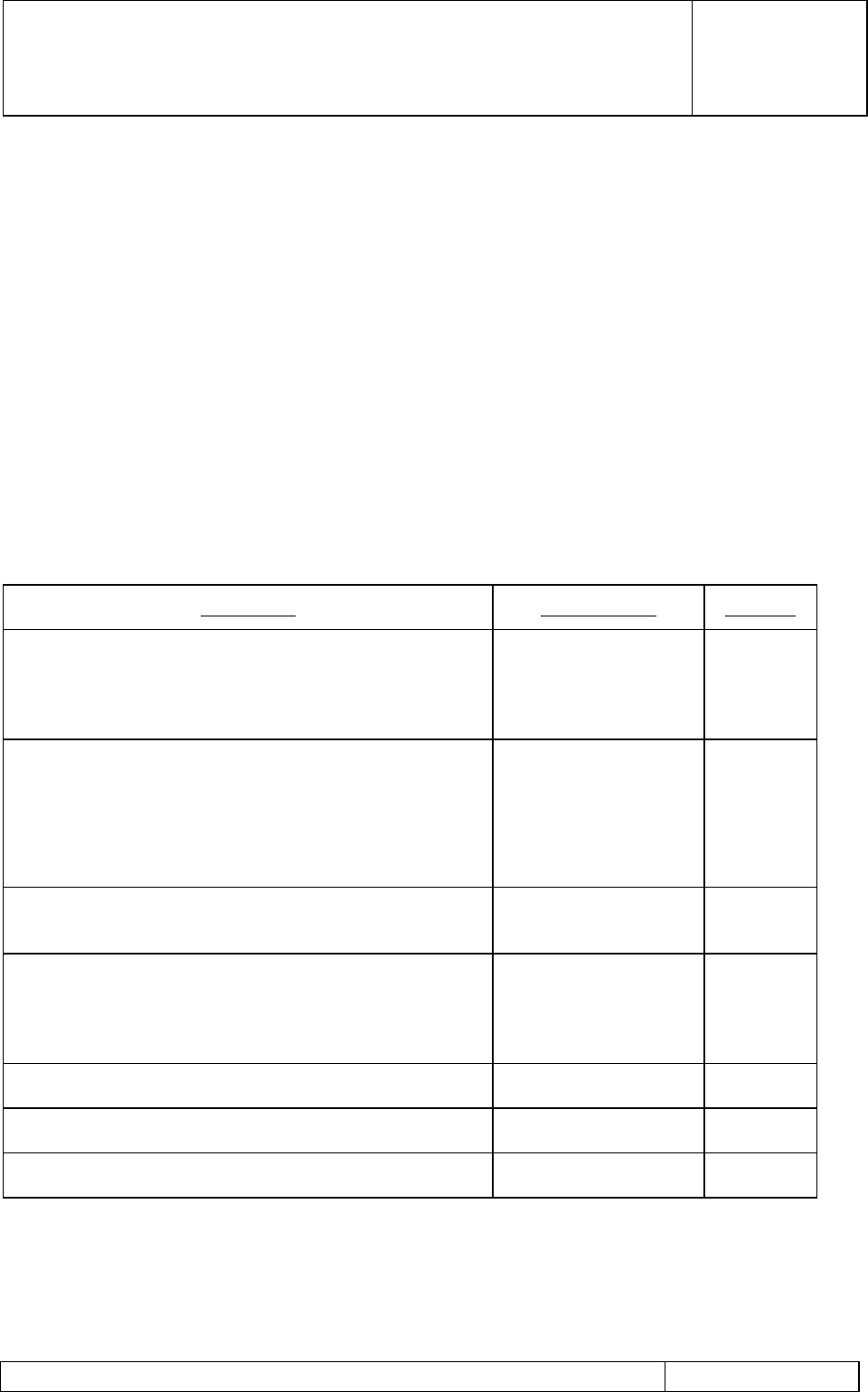
The three sector MHA system comprises the following units:
Description Product Code Quantity
G3 MHA - duplexed RF / Bias Tee feed DAMPS800,
GSM900, DCS 1800 or PCS 1900 MHz frequency as
applicable
G20xxx (DAMPS800)
G20xxx (GSM900)
N20xxx (DCS1800)
S20xxx (PCS1900)
6 (2 per
Sector )
MHA Mounting Kit
Single-MHA mounting N04xxx 6 (2 per
Sector )
Dual-MHA mounting N0403601 3 (1 per
sector)
G3 PDU -48v (19” rack mount for Bias Tee)
(+ve ground / 24v / external optional) N02xxx 1
Single Bias Tee Assembly (Indoor)
(External Bias Tee optional) G03xxx (DAMPS800)
G03xxx (GSM900)
N03xxx (DCS1800)
S03xxx (PCS1900)
6
Cable Set (to suit individual installation) N05xxx 1
Antenna Line Protocol Model Kit (to use with VG MHA) N26001A1
DC Circuit Test Kit ‘D’ N0402901
NOTE: If the Variable Gain Masthead Amplifier is installed without Booster PDU, an Antenna Line
Protocol Modem Kit will be required to set the gain of the MHA.
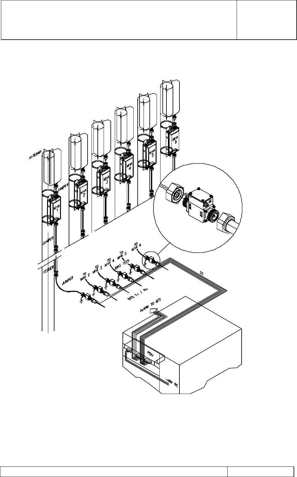
A System Interconnection diagram is shown in Figure 1.
G3 MHA INSTALLATION AND
OPERATING MANUAL
00/OSM/0002
ISSUE 1
May 2000
REMEC-Airtech G3 Masthead Amplifier Installation and Operating Manual Page 6 of 59
Figure 1 MHA System Interconnection Diagram with Bias Tees

G3 MHA INSTALLATION AND
OPERATING MANUAL
00/OSM/0002
ISSUE 1
May 2000
REMEC-Airtech G3 Masthead Amplifier Installation and Operating Manual Page 7 of 59
1.1.1 System Operation
The MHA system is used to enhance the uplink radio path from the remote subscriber to
the BTS. The MHA has been designed for the simple upgrade of an existing DAMPS800,
GSM900, DCS1800 or PCS 1900 cellular network or for the improved cost-effectiveness of
initial Network roll-out by the addition of a Low Noise Amplifier at the masthead with
minimum cable loss from the antenna.
The MHA accepts a single BTS and Antenna feeder cable such that the unit can be fitted
in-line with the existing cable at the masthead. The unit utilises a Bias Tee power feed
arrangement to enable the supply to be fed through the RF coaxial cable without the need
for any further cable installation for site upgrade.
The MHA is fitted with high performance low loss/high selectivity duplexers to enable the
transmit RF to pass from BTS to Antenna with < 0.5dB loss. The duplexers ensure high
Tx/Rx isolation, enabling the reception of low level signals from the mobile. The LNA is
fitted between the Rx duplexer filters to provide approximately 12dB of Rx signal gain. The
LNA comprises two low noise GaAs FET amplifiers operating in parallel for improved
reliability and higher IP3 performance. A BITE detection circuit is fitted for LNA fault
detection with an RF bypass circuit becoming operational upon a total LNA failure, i.e. in
the unlikely event that both FETs fail or loss of DC power to the LNA.
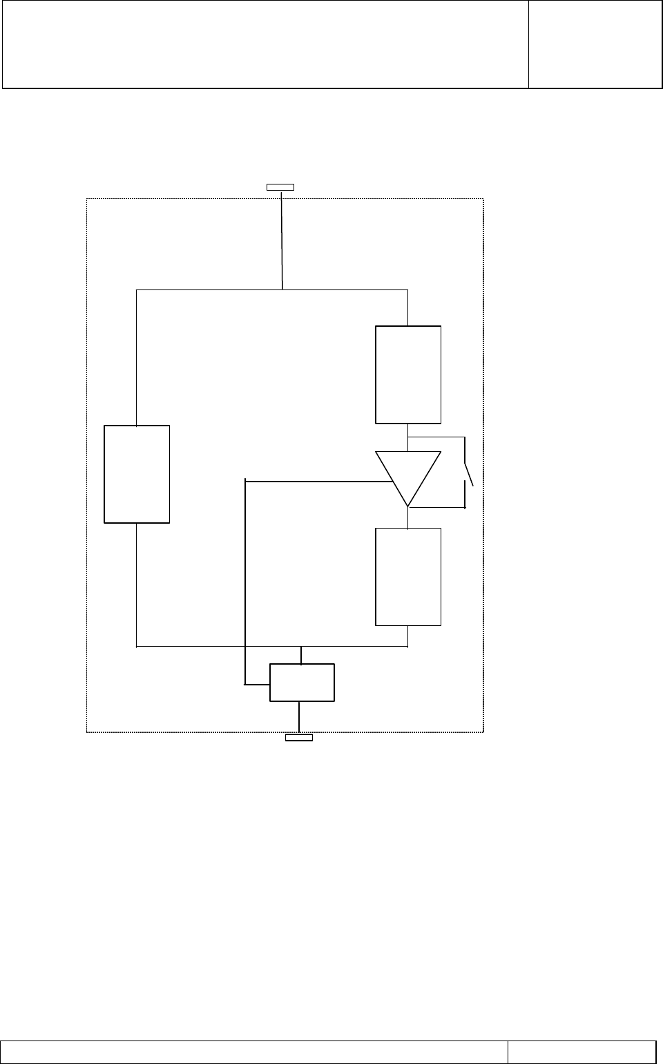
A block schematic of the signal flow within the MHA is shown in Figure 2
The MHA Low Noise Amplifier is supplied with +12.25V DC from the BTS RF feeder cable.
This is achieved by using Bias Tee power injection at both the MHA and the BTS feeder
cable interfaces.
The Bias Tee assembly has a low RF loss while providing DC injection/tap-off for the LNA
power feed. The unit also provides protection against the transient effects that may be
induced by lightning strikes to any part of the tower.
The overall system of 6 MHAs is supplied from a Power Distribution Unit (PDU) which
provides 6 separate +12.25V outputs via a multi-way cable assembly to the Bias Tee.
Each PDU output has a current detection window to monitor the LNA operation. Should
the MHA current fall outside the pre-set ‘normal’ operating current window, the PDU alarm
will be activated. The PDU has individual indicators for each MHA alarm with an overall
summary output alarm being provided to the BTS supervisory system. Each output and
alarm detection circuit can be separately switched for MHA muting.
The PDU operates from a -48V DC supply input from within the BTS support cabinet. The
-48V DC is converted to +12V DC for the MHA's using a dc-dc converter.
A variety of interconnecting cable kits can be provided to enable the flexible installation of
the PDU and to interconnect with the Bias Tee assemblies.
G3 MHA INSTALLATION AND
OPERATING MANUAL
00/OSM/0002
ISSUE 1
May 2000
REMEC-Airtech G3 Masthead Amplifier Installation and Operating Manual Page 8 of 59
Figure 2Masthead Amplifier Circuit Schematic
ANT port
Rx
Tx LNA and
bypass switch
Rx
BTS port
DC
Bias
Tee
G3 MHA INSTALLATION AND
OPERATING MANUAL
00/OSM/0002
ISSUE 1
May 2000
REMEC-Airtech G3 Masthead Amplifier Installation and Operating Manual Page 9 of 59
1.1.2 Interfaces
1.1.2.1 Masthead Amplifier
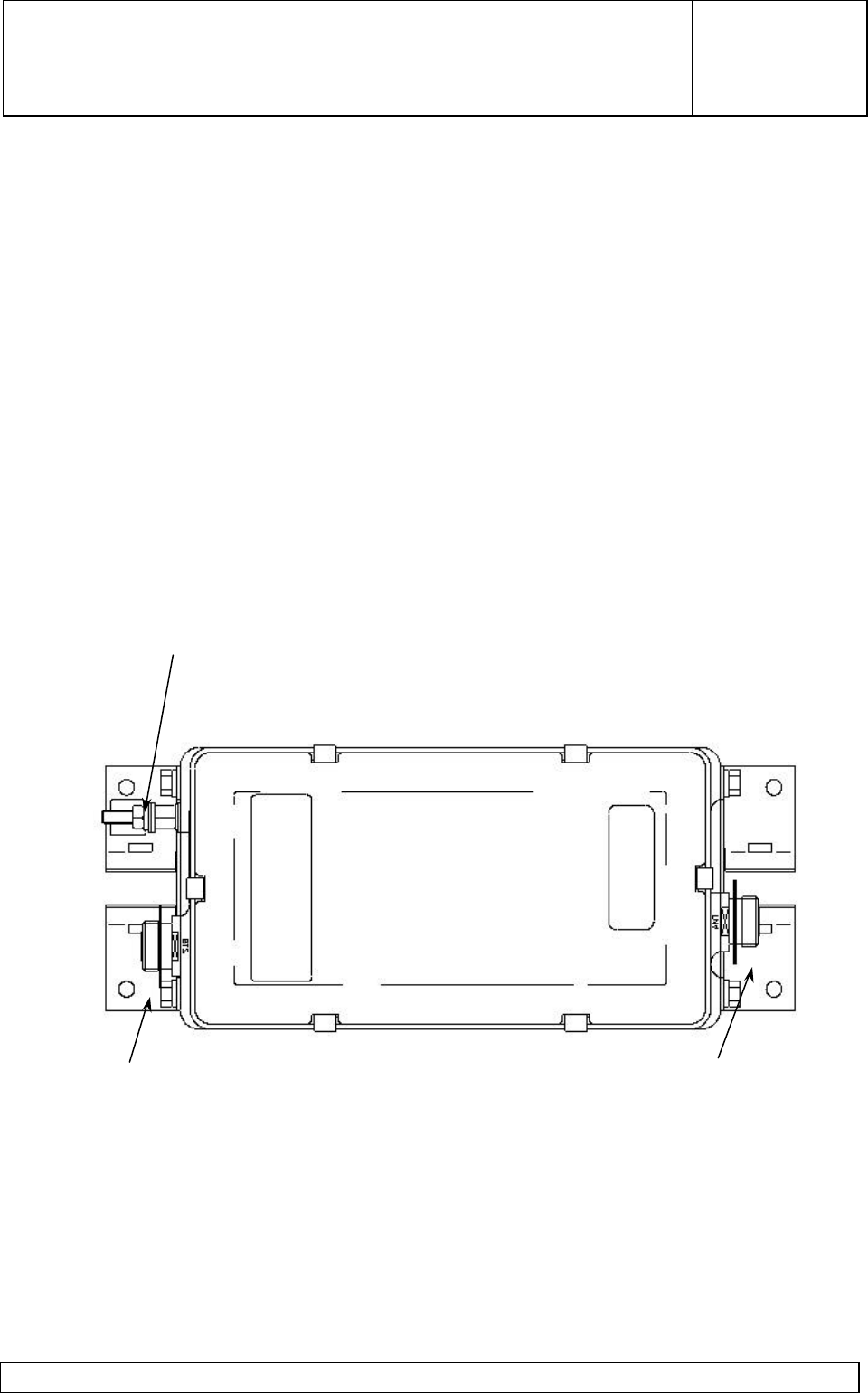
The MHA is provided with the following electrical interfaces (refer to Figure 3):
a) 7/16 Female (BTS): This is the connection for the duplexed Tx/Rx signals to/from the
BTS. In addition to providing for RF transmission, this connector provides for DC feed
via the RF cable and Bias Tee assembly.
b) 7/16 Female (ANT): This is the connection for the Tx/Rx Antenna. This port should be
as close as possible to the antenna with the connection being made with the
shortest/lowest loss interconnecting cable practicable.
c) M8 Earth Stud: This provides the Primary Lightning protection earth for the MHA. The
earth cable should be of the largest cross sectional area and shortest length
practicable and should be connected to a suitable earth point on the mast structure.
Figure 3Masthead Amplifier Interfaces
7/16 FEMALE (BTS)
M8 EARTH STUD
7/16 FEMALE (ANT)

G3 MHA INSTALLATION AND
OPERATING MANUAL
00/OSM/0002
ISSUE 1
May 2000
REMEC-Airtech G3 Masthead Amplifier Installation and Operating Manual Page 10 of 59
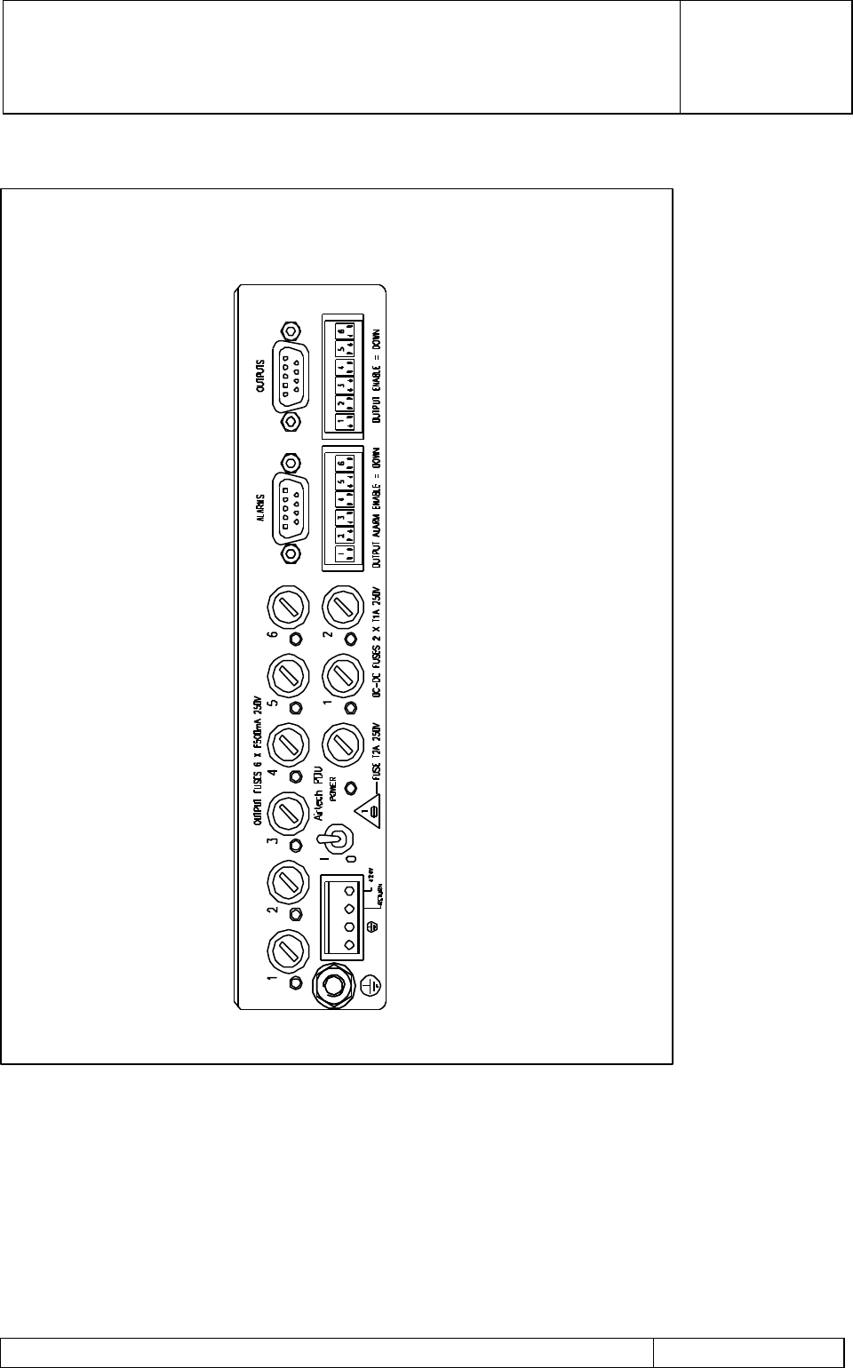
1.1.2.2 Power Distribution Unit
Note: The PDU is not required where DC power to the MHAs and Alarm functions are
provided directly from the BTS.
In a standard system configuration, an indoor PDU is used. Details of the indoor PDU
interfaces are given below. A brief description of the outdoor PDU interfaces is also
included in this section.
Indoor PDU
The PDU is provided with the following electrical interfaces (refer to Figure 4):
a) DC power input connector type SLA 4/90 3.2 SN: This connector is provided for the
primary -48V DC input from the BTS supply and is wired as follows:
Pin Number Function
1No Connection
2Equipment Ground
3Primary supply return
4-48V Primary Supply Feed
b) +12V DC Output connector type 'DB9S' 9 pole Female: This connector provides the 6
individually switched DC outputs to the Bias Tee for onward coaxial supply to the MHA
and is wired as follows:
Pin Number Function
1MHA No. 1 +12V DC Supply Output
2MHA No. 2 +12V DC Supply Output
3MHA No. 3 +12V DC Supply Output
4MHA No. 4 +12V DC Supply Output
5MHA No. 5 +12V DC Supply Output
6MHA No. 6 +12V DC Supply Output
70v DC return
80v DC return
9No connection

G3 MHA INSTALLATION AND
OPERATING MANUAL
00/OSM/0002
ISSUE 1
May 2000
REMEC-Airtech G3 Masthead Amplifier Installation and Operating Manual Page 11 of 59
c) Alarm Output connector type 'DB9P' 9 pole Male: This connector provides the Sector
and DC>DC Alarm Output and is wired as follows:
Pin Number Function
1Sector 1 Alarm.
2Sector 2 Alarm.
3Sector 3 Alarm.
4DC - DC Alarm.
50V Ground.
6Sector 1 Alarm.
7Sector 2 Alarm.
8Sector 3 Alarm.
9DC - DC Alarm.
d) M6 Earth Stud. Provides the Primary Lightning protection earth to the PDU. The earth
cable should be of the largest cross sectional area and of minimum length practicable
to provide maximum lightning protection.
G3 MHA INSTALLATION AND
OPERATING MANUAL
00/OSM/0002
ISSUE 1
May 2000
REMEC-Airtech G3 Masthead Amplifier Installation and Operating Manual Page 12 of 59
Figure 4Power Distribution Unit Interfaces (Indoor)
G3 MHA INSTALLATION AND
OPERATING MANUAL
00/OSM/0002
ISSUE 1
May 2000
REMEC-Airtech G3 Masthead Amplifier Installation and Operating Manual Page 13 of 59
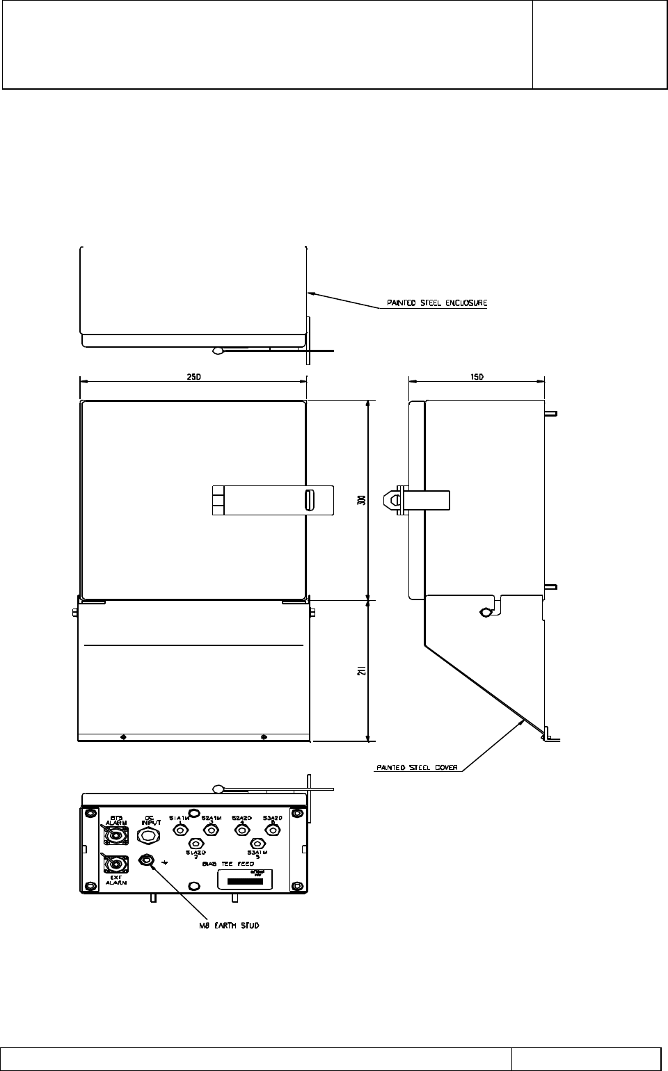
Outdoor PDU
The indoor compact PDU in housed inside a weatherproof enclosure to provide an
Outdoor PDU. Additional lightning protection is included within the enclosure. Details of
the outdoor PDU interfaces are shown in Figure 5
Figure 5Power Distribution Unit Interfaces (Outdoor)

G3 MHA INSTALLATION AND
OPERATING MANUAL
00/OSM/0002
ISSUE 1
May 2000
REMEC-Airtech G3 Masthead Amplifier Installation and Operating Manual Page 14 of 59
Outdoor PDU is provided with the following electrical interfaces:
a) DC power input connector type SLA 4/90 3.2 SN: This connector in on the compact
PDU unit inside the outdoor enclosure and is provided for the primary -48V DC input
from the BTS supply. An input cable is passed through the grommet (DC input) on the
enclosure panel and is wired as follows:
Pin Number Function
1No Connection
2Equipment Ground
3Primary supply return
4 -48V Primary Supply Feed
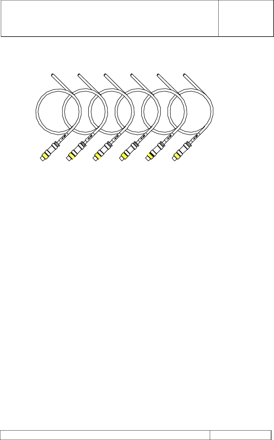
b) +12V DC Output connections to the Outdoor Bias Tees are provided using six cables
with ‘Binder’ connectors (one for each Bias Tee) shown in Figure 6. The cables are
passed through six ‘Bias Tee Feed’ grommets on the enclosure panel. PIN
connections on the connector block inside the enclosure are as follows:
Number on Block Function
1(+,-) MHA No. 1 +12V DC Supply Output and return
2(+,-) MHA No. 2 +12V DC Supply Output and return
3(+,-) MHA No. 3 +12V DC Supply Output and return
4(+.-) MHA No. 4 +12V DC Supply Output and return
5(+,-) MHA No. 5 +12V DC Supply Output and return
6(+,-) MHA No. 6 +12V DC Supply Output and return
c) BTS Alarm Output connector type '8 pin Metalok Bantam’ on the enclosure panel.
This connector provides the Sector and DC>DC Alarm Output and is wired as follows:
Pin Number Function
A and B Summary Sector Alarm.
C and D DC – DC Alarm
Second ‘8 pin Metalok Bantam’ connector (EXT Alarm) in normally not used.
G3 MHA INSTALLATION AND
OPERATING MANUAL
00/OSM/0002
ISSUE 1
May 2000
REMEC-Airtech G3 Masthead Amplifier Installation and Operating Manual Page 15 of 59
Figure 6Bias Tee Cable Kit for Outdoor PDU
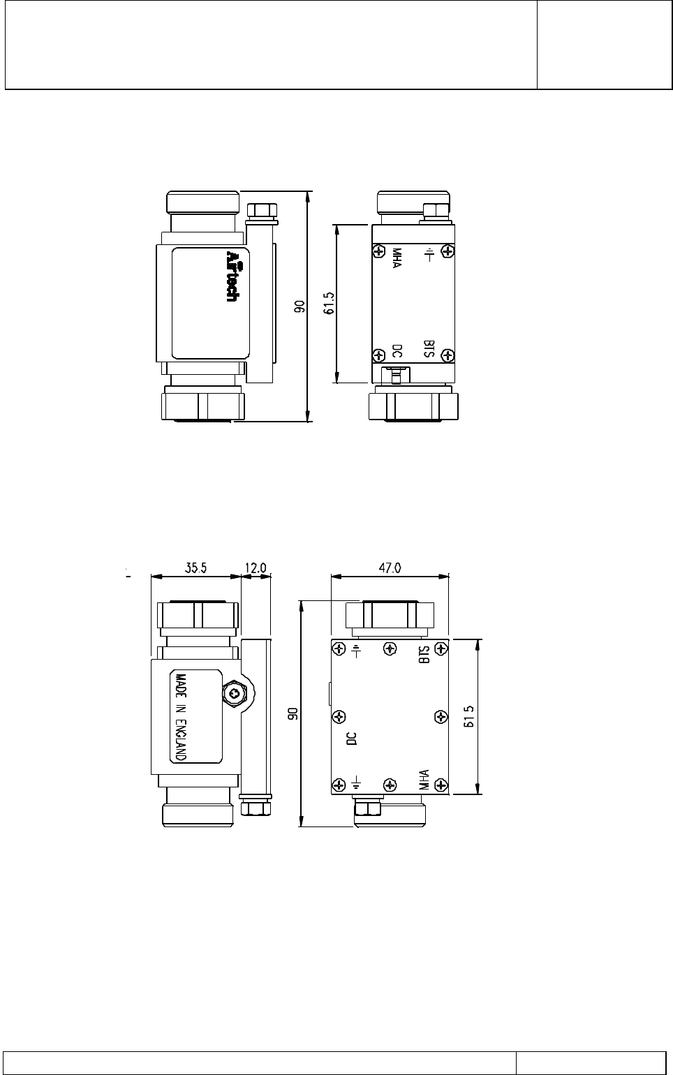
1.1.2.3 Bias Tee
The Bias Tee is provided with the following electrical interfaces (refer to Figure 7):
a) DIN 7/16 Female (BTS): This is the connection for the duplexed Tx/Rx signals to/from
the BTS.
b) DIN 7/16 Male (ANT): This is the RF output connection to the Antenna feeder cable.
As well as providing for RF transmission, this connector provides for DC feed via the
RF cable to the MHA.
c) PDU Input connector (type SMB Male for indoor Bias Tee, Binder for outdoor Bias
Tee): This connector provides the DC supply input to the Bias Tee for onward supply
to the MHA and it is wired as follows:
Pin Number Function
Inner Bias Tee +12V DC supply Input.
Outer Bias Tee DC return.
d) M6 Earth Stud: Provides the Primary Lightning protection earth to the Bias Tee. The
earth cable should be of the largest cross sectional area and of the minimum length
practicable to provide maximum lightning protection.
G3 MHA INSTALLATION AND
OPERATING MANUAL
00/OSM/0002
ISSUE 1
May 2000
REMEC-Airtech G3 Masthead Amplifier Installation and Operating Manual Page 16 of 59
Indoor Bias Tee
Outdoor Bias Tee
Figure 7Bias Tee Interfaces
Note: Alternative connector genders are available to suit cable interfaces.
G3 MHA INSTALLATION AND
OPERATING MANUAL
00/OSM/0002
ISSUE 1
May 2000
REMEC-Airtech G3 Masthead Amplifier Installation and Operating Manual Page 17 of 59
1.1.2.4 Cable Kit using indoor PDU and Bias Tees
The cable kit comprises the necessary cables and interfaces to enable the interconnection
of the PDU and Bias Tee units within the BTS cabinet.
The relevant product code is N0500XXX (XXX depends on BTS type) for a BTS using
quantity 6 off Bias Tees.
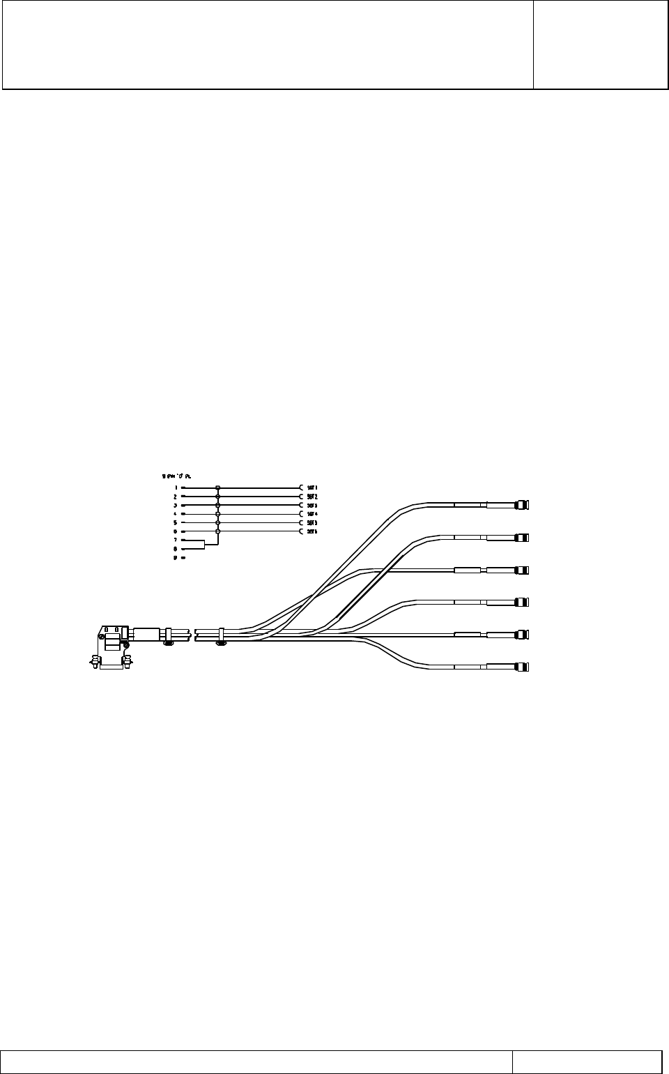
a) PDU Output port to Bias Tee (refer to Figure 8)
This cable comprises six individual screened coaxial cables with a 9 pole 90o free 'D'
type plug for connection to the PDU DC output socket. The six individual tails are
terminated with an SMB free socket for attachment to each of the 6 Single Bias Tee
DC inputs.
Figure 8PDU DC Output port to Bias Tee
G3 MHA INSTALLATION AND
OPERATING MANUAL
00/OSM/0002
ISSUE 1
May 2000
REMEC-Airtech G3 Masthead Amplifier Installation and Operating Manual Page 18 of 59
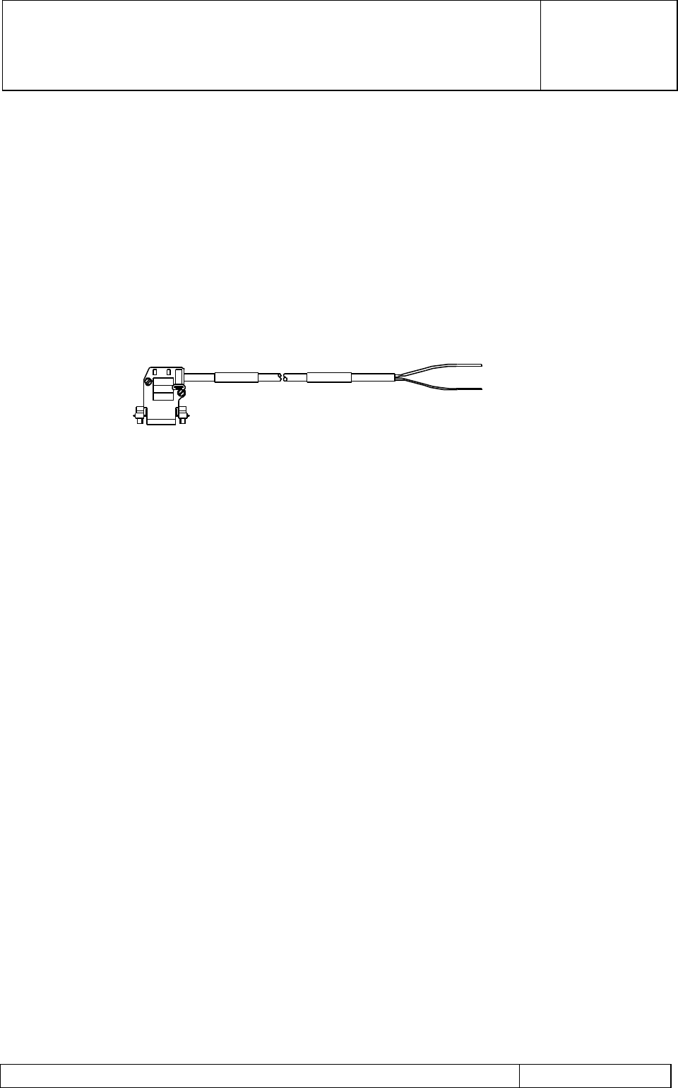
b) PDU Alarm to BTS Alarm port (refer to Figure 9)
This is an 8 conductor cable with a 9 pole 90o free 'D' type socket for connection to the
PDU Alarm output socket. The other end is un-terminated to enable installer
connection to the alarm concentrator PCB in the BTS cabinet.
Figure 9PDU Alarm port to BTS Alarm
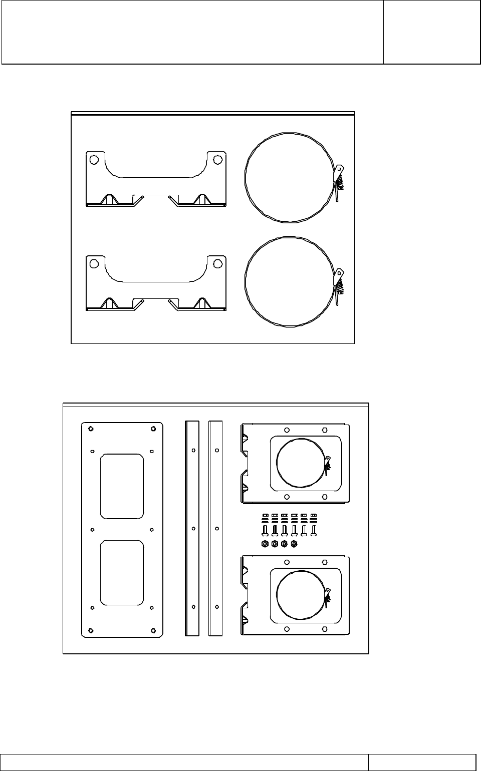
1.1.2.5 MHA Mounting Kit
The mounting kit comprises the brackets, fitted to both ends of the MHA, straps for pole
mounted configuration and bolts for wall mounted configuration. There are two types of
mounting bracket kits, Single-MHA mounting and Dual-MHA mounting as shown in Figure
10.
G3 MHA INSTALLATION AND
OPERATING MANUAL
00/OSM/0002
ISSUE 1
May 2000
REMEC-Airtech G3 Masthead Amplifier Installation and Operating Manual Page 19 of 59
Single MHA Mounting Kit
Dual MHA Mounting Kit
Figure 10 Mounting Bracket Kits

G3 MHA INSTALLATION AND
OPERATING MANUAL
00/OSM/0002
ISSUE 1
May 2000
REMEC-Airtech G3 Masthead Amplifier Installation and Operating Manual Page 20 of 59
1.2 Hardware Description
1.2.1 Masthead Amplifier
The MHA comprises a tower top mounted enclosure which is provided with fixing suitable
for wall or pole mounting. The enclosure is sealed to provide IP68 protection of the internal
components. The MHA is based upon a triplexer filter design with an integrated Low Noise
Amplifier and Bias Tee assembly. The whole internal module is formed from a single silver
plated assembly to provide best in class insertion loss performance.
The triplexer filters are arranged to provide a Low Loss transmit path by the use of a
bandpass filter between the BTS and Antenna ports. Each of the external ports includes
an internal diplexing junction to connect 2 off bandpass filters to the Tx filter.
The Rx bandpass filter connected to the Antenna port provides pre-selection of Rx signals
and protection from the high power transmitter signals. The Rx filter is connected to a Low
Noise Amplifier with approximately 12dB gain.
The LNA comprises a Quadrature coupled pair of GaAs FETs to improve IP3 high level
performance and reliability. The LNA contains internal BITE detection circuitry to indicate
failure of either FET and to signal a fault condition to the PDU within the BTS. In the
unlikely event that both FETs fail, the bypass circuit switches the LNA out of line. The
output of the LNA is then connected via a second Rx bandpass filter to the BTS port of the
MHA.
A Bias Tee assembly is fitted at the BTS port diplexer junction to enable a coaxial DC feed
from the BTS to be fed off to the LNA. The Bias Tee assembly contains DC blocking in the
RF path and RF blocking in the DC path. The unit has integral Lightning Protection to
provide clamping of any lightning induced voltages which could damage the LNA circuitry.
1.2.2 Power Distribution Unit
The MHA system is supplied with +12V DC from a Power Distribution Unit (PDU) which
provides 6 separate outputs at to each MHA from an input supply of -48V DC (other
options also available) derived from the BTS BBU. The conversion of the input at -48V to
a +12V output voltage is achieved by a dc-dc converter system. The PDU supply input
has transient and reverse power protection to prevent damage to the dc-dc assemblies.
The outputs of the dc-dc assembly provide a supply to each of the +12V outputs. Each
output has a front panel mounted Enable/Disable switch and a fuse for output protection.
A current monitoring circuit is fitted in series with the supply to each output. This detects
abnormal demand from the LNA and activates a summary alarm signal via a relay. The
current detection circuit alarm can be enabled/disabled by a front panel mounted switch.
Each alarm has its own indicator LED which confirms whether the MHA is OK (Green),
Faulty (Red) or Disabled (Extinguished). All outputs have internal secondary transient
protection against lightning.

G3 MHA INSTALLATION AND
OPERATING MANUAL
00/OSM/0002
ISSUE 1
May 2000
REMEC-Airtech G3 Masthead Amplifier Installation and Operating Manual Page 21 of 59
1.2.3 Bias Tee
The Bias Tee consists of an integrated body housing a lightning protection and DC
injection PCB and the RF ports for interconnection between the BTS and the MHA feeder
cables. The unit is designed to fit on top of the BTS, fitting between the antenna feeder
cable and the BTS output. The Bias Tee assembly contains DC blocking in the RF path
and RF blocking in the DC path. The DC is fed from the PDU input and onto the coaxial
cable to the Antenna/MHA to power the LNA. The Bias Tee has integral Lightning
Protection using a Gas Discharge Tube and transorb to provide clamping of any lightning
induced voltages which could damage the PDU. An input DC feed-through filter is
incorporated to enhance the EMC performance.
1.2.4 Cable Kit
The Bias Tee Kit includes 2 cables for:
• DC (Octopus cable for indoor PDU, six separate for outdoor PDU) from PDU to
the six Single-way Bias Tees
• Alarms from PDU to BTS
All cables are plug to socket arrangements for module interconnection.
1.2.5 MHA Mounting Kit
There are two types of MHA mounting brackets. The Single-MHA mounting bracket kit
allows a single MHA to be mounted on either a pole or a flat surface. The Dual-MHA
mounting bracket kit allows two stacked MHAs to be mounted on a pole or a flat surface.
Pole mounting requires straps and flat surface mounting requires bolts.
Two Single-MHA mounting bracket kits are required for two MHAs per sector system. Six
kits are required for a three-sector site.
One Dual-MHA mounting kit is required for two stacked MHAs per sector system. Three
kits are required for a three-sector site.

G3 MHA INSTALLATION AND
OPERATING MANUAL
00/OSM/0002
ISSUE 1
May 2000
REMEC-Airtech G3 Masthead Amplifier Installation and Operating Manual Page 22 of 59
2 Installation Manual
2.1 General
CAUTION
PRIOR TO INSTALLING THE MHA SYSTEM OR ANY OF ITS COMPONENTS,
ENSURE THAT THE BTS TRANSMITTER OUTPUT IS TURNED OFF AND
THAT PRECAUTIONS ARE TAKEN TO ENSURE THAT THE TRANSMITTER
CANNOT BE ACTIVATED DURING THE EQUIPMENT INSTALLATION.
Installation of REMEC-Airtech MHA adjacent to the antenna on a Base Station tower
enhances the Rx path sensitivity and improves the general BTS performance. There is a
detailed description of the technical performance of the REMEC-Airtech MHA in Section
2.4.
Installation is extremely straightforward and this manual is designed to give
recommendations for a long and reliable life from the REMEC-Airtech MHA unit.
REMEC-Airtech recommend that the TERACOM™ (or equivalent) termination connectors
be used for all RF feed lines and jumpers. The connectors are suitable for use with RF 50
Ohm cables of various diameters. (½”, 7/8”, and 1 5/8” ). TERACOM™ part numbers are
shown in the table in Section 2.1.1.
REMEC-Airtech supply brackets for mounting the MHA to the tower. The brackets may be
supplied already connected to the MHA so that the only action necessary is to fix the MHA
to a suitable tower member or surface. If the brackets are not already attached, fit one to
the top and one to the bottom of the MHA using bolts provided. The REMEC-Airtech G3
MHA can be mounted in any recommended orientation to provide maximum flexibility for
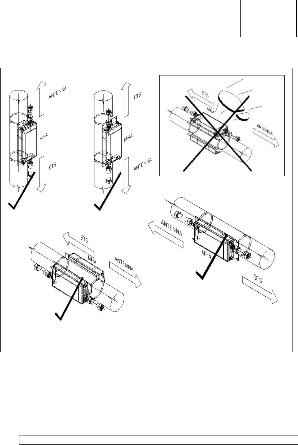
the installer (see Figure 11). Ensure that the MHA is not installed where it may be used as
a foothold. If the MHA is to be attached to a vertical round pole using the clamps provided
in the kit, the pole should be between 75mm and 150 mm in diameter.
The bracket system is also suitable for mounting the MHA to a vertical wall or similar
surface using the bolts or screws through the holes already punched in the MHA brackets
for this purpose.
Mounting the MHA in a method not approved by REMEC-Airtech may invalidate the
Warranty on the MHA unit. If in any doubt consult REMEC-Airtech on the following
numbers:
REMEC-Airtech in Europe, Tel: +44(0)1296 319 319 Fax: +44(0)1296 319 200
REMEC-Airtech Inc., Dallas, USA Tel: (214) 443 9106 Fax: (214) 443 9487
REMEC-Airtech Far East, Malaysia, Tel: +603 795 1270 Fax: +603 795 1249

G3 MHA INSTALLATION AND
OPERATING MANUAL
00/OSM/0002
ISSUE 1
May 2000
REMEC-Airtech G3 Masthead Amplifier Installation and Operating Manual Page 23 of 59
2.1.1 Recommended RF Cable Installation Components
Cable Reference Cable Type & Diameter Teracom™ Reference Cable Bracket Reference
BTS to Tower Top RF 1 5/8"–50 Ohm 716f-F158-B N/A
Tower Top to MHA
( Jumper ) RF 1/2"- 50 Ohm 716f-F012-B
716m-F012-B
N/A
MHA to Antenna
( Jumper ) RF 1/2"- 50 Ohm 716f-F012-B N0400401
or N0400101
TERACOM ™ is the trade mark of TERACOM Components AB, S-242 Hörby, Sweden
2.1.2 Installation Summary and Mounting Configuration
This section gives a summary of installation instructions for an MHA configuration using a
Single-MHA mounting bracket kit. Recommended mounting orientations are shown in
Figure 11. Ensure that the MHAs are not installed where they may be used as a foothold.
Same installation procedures and precautions must be adhered to when installing two
MHAs using a Dual-MHA mounting bracket kit.
G3 MHA INSTALLATION AND
OPERATING MANUAL
00/OSM/0002
ISSUE 1
May 2000
REMEC-Airtech G3 Masthead Amplifier Installation and Operating Manual Page 24 of 59
REMEC-Airtech supply brackets for mounting the
Masthead Amplifier (MHA) to the tower already fitted to
the MHA so that the installation is as simple as
possible.
RF Jumpers should be ½” diameter and as short as is
practical.
RF lines should not be bent through tight bends, and
connectors should not be side-loaded. Consider this
during siting of the MHA.
Figure A GROUNDING STUD
BASE –STATION JUMPER CONNECTION
ANTENNA JUMPER CONNECTION
Figure B
Figure C
Connect the MHA to the Grounding Bus-
bar using an adequate cable (Figure B).
(Max resistance to Ground 27 mΩ)
REMEC-Airtech can supply a suitable
copper cable of 35 mm2 cross section
and 1.2 M long.
Note: A lightning strike with inadequate
Grounding may result in permanent
damage to the MHA and will invalidate
the Warranty.
The REMEC-Airtech G3 MHA is a fully sealed IP68
rated unit which may be mounted in any orientation.
You should choose the most appropriate orientation
to give the shortest and neatest cable runs for
minimum loss. (Figure C)
For pole mounting use the clamps provided in the kit.
The pole diameter should be between 75mm and 150
mm.
For more details please refer to the Installation
Instructions or call REMEC-Airtech on:
+44 (0)1296 319 319 ( Europe )
(214) 443 9106 ( USA )
+603 795 1270 (Far East)
SUMMARY INSTALLATION INSTRUCTIONS FOR
REMEC-AIRTECH G3 MASTHEAD AMPLIFIERS
G3 MHA INSTALLATION AND
OPERATING MANUAL
00/OSM/0002
ISSUE 1
May 2000
REMEC-Airtech G3 Masthead Amplifier Installation and Operating Manual Page 25 of 59
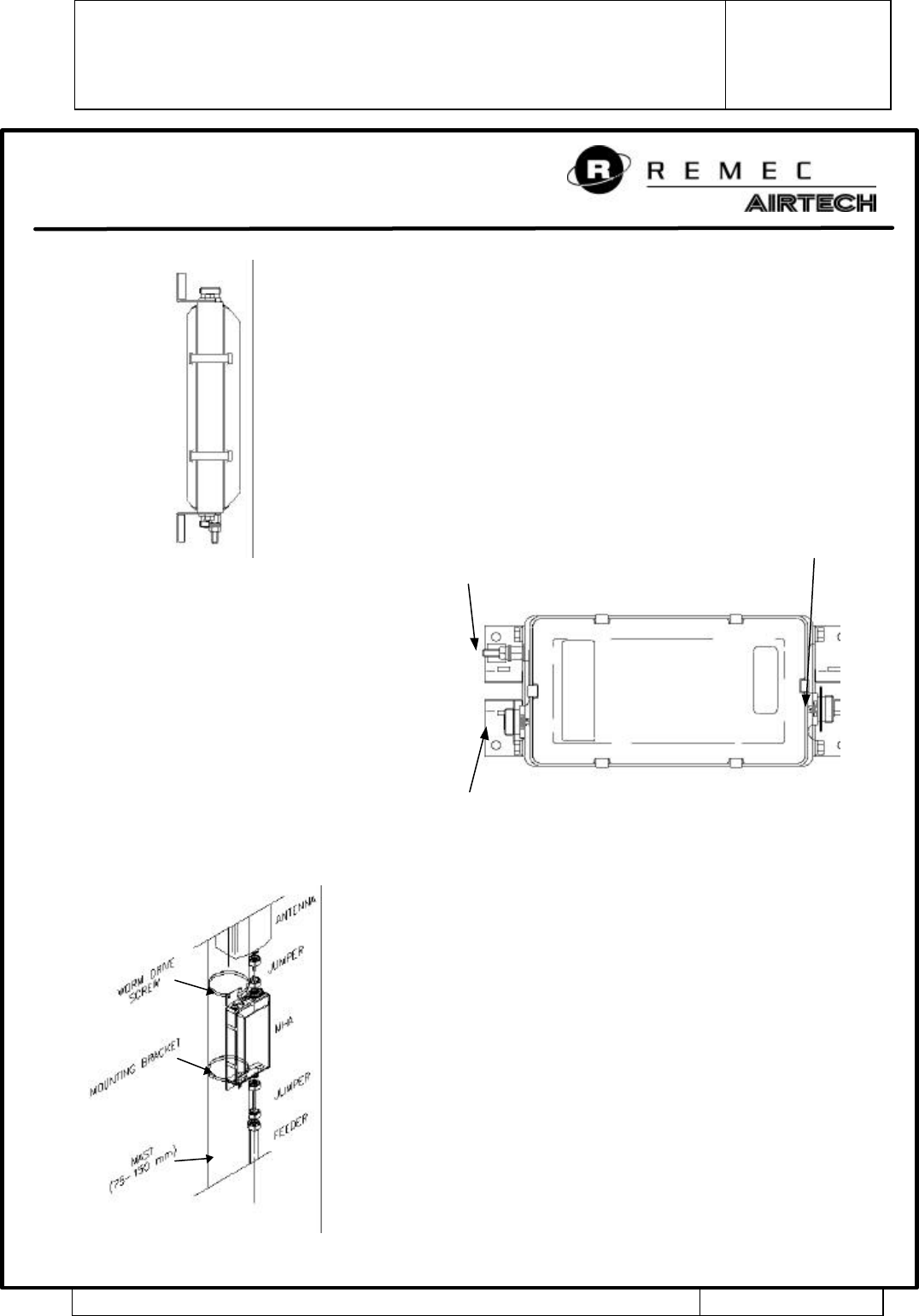
Figure 11 G3 MHA - Typical Mounting Configuration

G3 MHA INSTALLATION AND
OPERATING MANUAL
00/OSM/0002
ISSUE 1
May 2000
REMEC-Airtech G3 Masthead Amplifier Installation and Operating Manual Page 26 of 59
2.2 Installation of Masthead Amplifier (MHA)
2.2.1 General Mounting Instructions
The hardware for the installation arrives at the Base Station (BTS) site in two separate
parts:-
1) The REMEC-Airtech Mast Head Amplifier (MHA) complete with brackets.
2) The MHA Mounting Kit containing mounting bracket system, mounting straps, the
necessary nuts and washers and, if ordered, the MHA Ground cable.
Procedure Overview
The installation procedure is made simple by the fact that the REMEC-Airtech G3 MHA is
supplied with easy to fit mounting brackets. Simply remove the MHA from its packing
material, fit the Single-MHA or Dual-MHA mounting brackets if not already fitted, and attach
it to a pole using straps or any flat surface using bolts provided with the mounting kit.
Then, connection is made from the BTS feed to the MHA BTS port using the BTS jumper
cable. Finally the connection is made from the antenna connector to the ANT port on the
MHA using the antenna jumper cable.
Note: The recommended cable for jumpers is ½” RF – 50 Ohm cable (or equivalent) with
TERACOM™ (or equivalent) connectors as listed in the table on Section 1.2 of this
manual.
Tools Required for Installation
½ inch drive Sockets - 8mm, 10mm
½ inch drive ratchet
½ inch drive Torque wrench
Detailed installation procedures are given in the next Section.
G3 MHA INSTALLATION AND
OPERATING MANUAL
00/OSM/0002
ISSUE 1
May 2000
REMEC-Airtech G3 Masthead Amplifier Installation and Operating Manual Page 27 of 59
2.2.2 Detailed MHA Installation Procedure
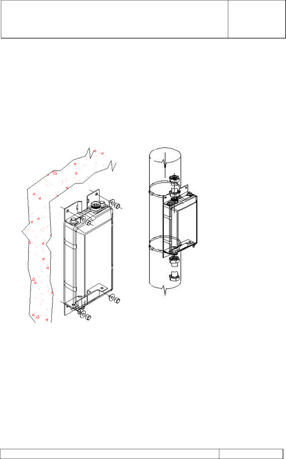
The MHA can be mounted on a flat surface or on a pole as shown in . A single MHA mounting is
shown in this diagram.
Two MHAs stacked on top of each other can be similarly mounted on a flat surface or a pole using a
Dual-MHA mounting bracket-kit. Dual MHA mounting is shown in
Figure 12 Flat Surface and Pole Mounting of a Single MHA
G3 MHA INSTALLATION AND
OPERATING MANUAL
00/OSM/0002
ISSUE 1
May 2000
REMEC-Airtech G3 Masthead Amplifier Installation and Operating Manual Page 28 of 59
Figure 13 Flat Surface or Pole Mounting of Stacked Dual MHAs
a) Open the MHA outer box and remove the MHA and the Mounting Kit

G3 MHA INSTALLATION AND
OPERATING MANUAL
00/OSM/0002
ISSUE 1
May 2000
REMEC-Airtech G3 Masthead Amplifier Installation and Operating Manual Page 29 of 59
b) Prior to installing the MHA assembly ensure that there is sufficient space available for
the mounting of the equipment to the mast pole or to the wall structure. This
necessary clearance should include access for cable bend radius and termination of
the feeder.
The REMEC-Airtech G3 MHA is sealed to a full IP68 rating and may therefore be
fitted in any orientation. This feature is of particular benefit as it allows for the
shortest cable runs and, therefore, system losses as well as for neat installation
practice including, if possible, hiding of the MHA where aesthetic considerations are
key. The unit should not be mounted in positions where it may be used as a
foothold for tower personnel as this can cause internal damage which may not be
covered by the REMEC-Airtech Warranty. (See Figure 11, Section 2.1.2)
c) The REMEC-Airtech G3 MHA is supplied with the mounting brackets. Fit the single-
MHA or dual-MHA mounting, as necessary, if not already fitted. The MHA/MHAs may
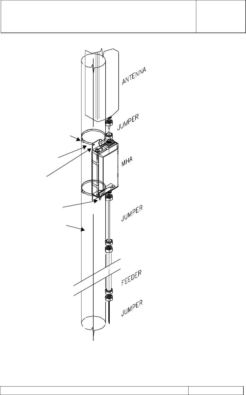
be attached to an antenna pole by the use of the two adjustable strap assemblies
which should be fitted to the upper and lower mounting brackets. Thread each of the
straps through the two slots provided in the mounting brackets. Wrap the straps
around the mounting pole and locate into the worm drive screw assembly as detailed
in Figure 14. Stacked Dual MHAs are also similarly mounted on the pole. The two
screw assemblies should then be adjusted using a 10 mm open ended spanner or
socket assembly, ensuring that the torque applied to the screw does not exceed 2
Nm.
d) If the MHA is to be mounted on a flat (vertical or horizontal) surface, then this can be
achieved using M6 bolts of an appropriate length. The bolts are passed through the
holes provided in the mounting bracket already attached to the unit.
e) Connect the MHA earth stud to the antenna earthing arrangement using a cable of at
least 24 mm2 cross-sectional area. Fit the Ground Cable to the brass M8 stud on the
front of the MHA using the brass washer, lock-washer and nut which should first have
been removed from the MHA stud, and route the ground cable downwards. Tighten
the M8 nut to the correct torque. Fit the lower cable lug to a suitable ½” diameter bolt
grounding point on the mast. Ensure that the torque applied to the MHA grounding
stud does not exceed 10 Nm. This torque setting must not be exceeded or damage
may occur to the unit, which will not be covered by the REMEC-Airtech Warranty.
This maximum torque setting is marked clearly on a yellow label attached to the
mounting bracket adjacent to the Earth Stud.
Note: If the Ground cable has not been ordered from REMEC-Airtech the installer
should ensure that the overall resistance of the Ground path from the MHA stud to
Ground does not exceed 1000 mΩ. The REMEC-Airtech recommended cable has a
cross-section of 35 mm2 and a length of 1.2m.

G3 MHA INSTALLATION AND
OPERATING MANUAL
00/OSM/0002
ISSUE 1
May 2000
REMEC-Airtech G3 Masthead Amplifier Installation and Operating Manual Page 30 of 59
f) Connect the antenna jumper cable from the output of the antenna to the port labelled
ANT on the MHA. Ensure that the connectors are correctly mated then tighten each
connector to 20 - 25Nm using a torque spanner. This maximum torque setting is
marked clearly on yellow plastic rings which are positioned over each connector.
While the connectors used in the REMEC-Airtech G3 MHA are of a unique stress-
protected design, severe abuse can lead to damage of the connectors which may not
be covered by the REMEC-Airtech Warranty. Ensure that the bend radii of the cable is
not placing sideways stress on the cable or connectors.
g) Connect the BTS feeder cable to the BTS port of the MHA. Ensure that the cable is
correctly mated and securely connected observing the same precautions as used for
the ANT connector detailed above. Ensure that the bend radius of the cable is not
placing sideways stress on the cable or connectors.
h) Once all connections are terminated on to the MHA each of the cable entry points
should be sealed using an approved weatherproofing tape (Denso or similar). Ensure
that any excess cable is securely attached to the mast to prevent movement or
vibration which could lead to long-term connector or cable damage.
G3 MHA INSTALLATION AND
OPERATING MANUAL
00/OSM/0002
ISSUE 1
May 2000
REMEC-Airtech G3 Masthead Amplifier Installation and Operating Manual Page 31 of 59
Figure 14 Installation of the MHA using a Single-MHA Mounting Bracket kit.
WORM DRIVE SCREW
TENSION BAND
MOUNTING BRACKET
M8 EARTH POINT
MAST ∅75 –150mm
G3 MHA INSTALLATION AND
OPERATING MANUAL
00/OSM/0002
ISSUE 1
May 2000
REMEC-Airtech G3 Masthead Amplifier Installation and Operating Manual Page 32 of 59
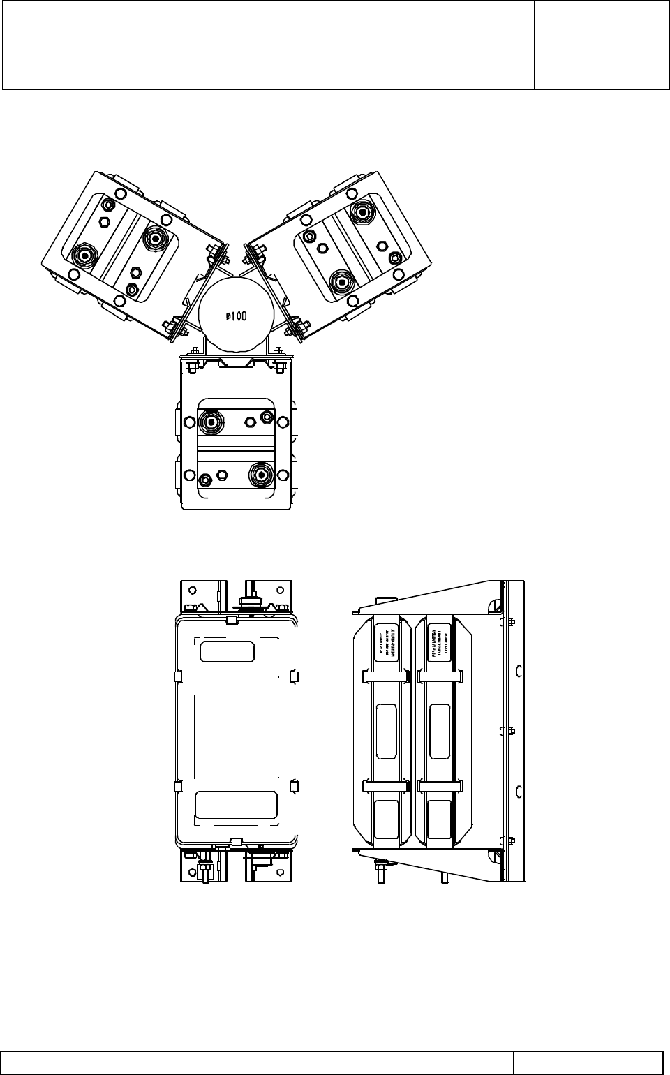
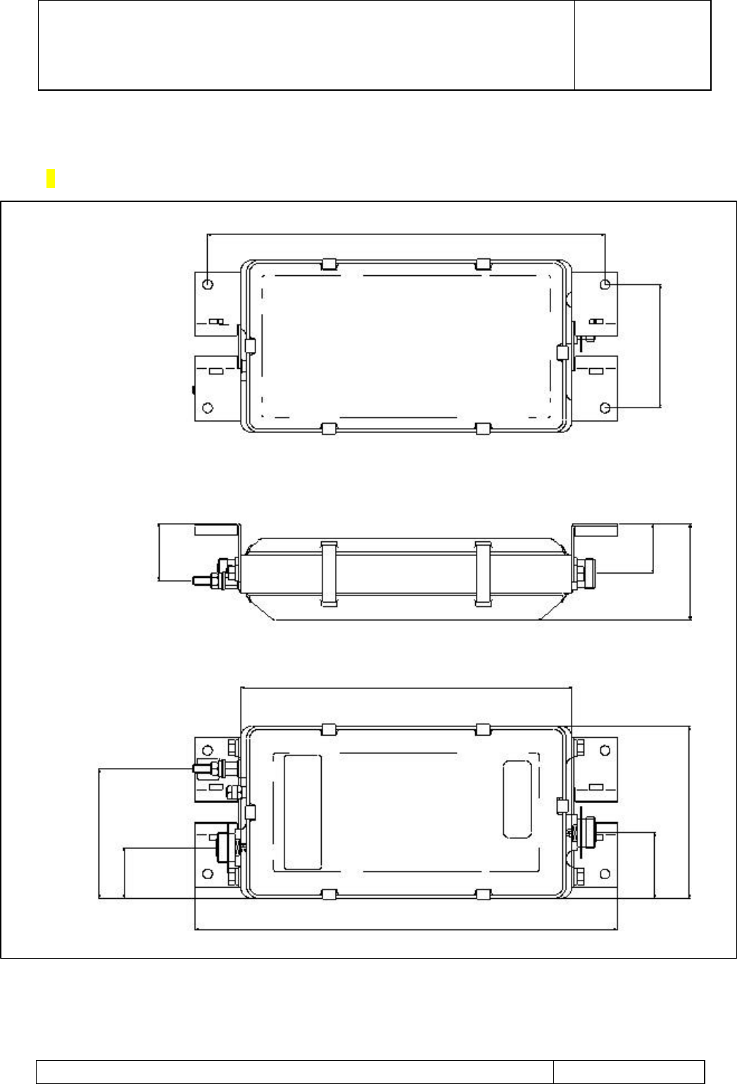
Figure 15 Interface Drawing of G3 MHAs
374
116
54.3
(67.2)
47
(60.2)
92
(120)
162
61.8
398
47.8
122
NOTE
Dimensions in brackets are
for G20xxx (GSM900,
DAMPS800) MHAs.
All other dimensions are
common to PCN1800,
PCS1900. DAMPS800 and
GSM900 MHAs

G3 MHA INSTALLATION AND
OPERATING MANUAL
00/OSM/0002
ISSUE 1
May 2000
REMEC-Airtech G3 Masthead Amplifier Installation and Operating Manual Page 33 of 59
2.2.3 Installation of Bias Tee
a) Ensure the BTS is turned off and all transmitters inhibited.
b) Remove the antenna feeder cables from the existing antenna output connectors (on
top of the BTS cabinet) ensuring that each cable assembly is identified with its mating
location. Note: loosen the cable support clamps where necessary to provide sufficient
movement of cables.
c) Attach a Bias Tee assembly to each antenna output cable from the top of the BTS
cabinet. Tighten each connector to 14 Nm using a torque spanner whilst ensuring a
counter torque is applied to the connector body.
d) Connect each Bias Tee earth point to the cabinet primary earth using a short length of
6 mm2 earth cable. This should be terminated in an M6 tag for connection to the Bias
Tee assembly ensuring that the earth connection is tightened to not greater than 4
Nm.
e) The external antenna feeder cables should be re-connected to the Bias Tees,
ensuring that each antenna is connected to its original BTS output port. Tighten each
connector to 14 Nm torque whilst ensuring a counter torque is applied to the connector
body. Re-tighten the cable support clamps where necessary to secure the cables.
2.2.4 Installation of Power Distribution Unit
Note: A PDU is not required where DC supplies to the MHAs and the Alarm functions
are provided directly from the BTS.
Instructions a), b), and c) below are for a rack-mountable PDU. Locate and secured the
non-rack-mountable PDU in a convenient position inside BTS and follow instructions d)
and e) to compete the installation.
a) Locate a suitable position in the BTS 19” support cabinet for the installation of the
PDU. Where possible leave a 1u (44mm) space between the rectifiers and the PDU.
b) Insert four off ‘M6 cage nut’ assemblies into the equipment mounting rails within the
cabinet to accept the fixing positions of the PDU.
c) Install the PDU into the cabinet using four off M6 x 12 fixing screws and the previously
fitted cage nut assemblies.
These fixing screws should be tightened to not greater than 6 Nm.
d) Attach a 2.5mm2 earth cable between the cabinet earth and the front panel earth point
of the PDU. This cable should be fitted with an M6 cable tag for attachment to the
PDU. Ensure that the PDU earth bolt is tightened to not greater than 4 Nm.
e) Ensure that the PDU circuit supply breaker is turned off at the supply distribution
board. Connect the PDU supply cable from the supply to the DC input connector of
the PDU. Ensure that the connector latch is securely mated. The DC supply cable
may be supported by tie wrapping with cable ties to the cabinet mounting rails.

G3 MHA INSTALLATION AND
OPERATING MANUAL
00/OSM/0002
ISSUE 1
May 2000
REMEC-Airtech G3 Masthead Amplifier Installation and Operating Manual Page 34 of 59
2.2.5 Installation of Cables
a) Ensure that the cable kit contains the following items:
• Cable assembly Octopus to Bias Tee.
• Cable assembly PDU alarm to BTS Alarm.
b) Connect the Bias Tee ‘Octopussy’ cable assembly to the PDU DC output port.
Connect each of the 6 DC tails to the Bias Tee assemblies, ensuring that the correct
DC cables are terminated to the appropriate Bias Tee.
c) Connect Alarm cable assembly to the PDU ALARM output port. Connect the fly-lead
tails to the BTS alarm concentrator Terminal Block pins TBD (Customer Defined).
d) Ensure that all cable assemblies are suitably routed and tidily secured to the cabinet
structure using cable ties as required to prevent accidental damage.
e) The equipment is now ready for functional testing.
2.3 Grounding Cables and Lightning Protection
2.3.1 Clamping of cables and correct Grounding
All RF and Ground cables should be clamped from movement at suitable intervals along
their full length. The clamping should be arranged so that the end connectors are not
subjected to significant loading either in tension or compression or bending. The clamping
should also prevent movement of the cables in high wind, which could eventually cause
degradation of the performance of cables and connectors.
2.3.2 Ground Path Requirements
The Ground/Earth cable connecting the MHA Ground/Earth stud to the bus-bar should be
of 35mm2 section copper to minimise the resistance. Note: Tests indicate that a 10 mm2
copper is likely to fuse in the event of a severe lightning strike induced current (for example
25kA).
The cable specified for REMEC-Airtech Ground/Earth cable may be up to 50 metres in
length, at which point its resistance is calculated at 28 mΩ. It is desirable to minimise the
overall resistance from MHA to Reference Ground even if this requires a long Ground/Earth
cable from the MHA to the bus-bar.
2.3.3 Grounding/Earthing of the MHA
The MHA contains circuits which provide lightning protection against high voltages which
may appear between signal or power lines and the metal case, including the outer parts of
the connectors and the screens of the RF cables.
G3 MHA INSTALLATION AND
OPERATING MANUAL
00/OSM/0002
ISSUE 1
May 2000
REMEC-Airtech G3 Masthead Amplifier Installation and Operating Manual Page 35 of 59
To reduce these voltages when they occur, a Gas Discharge device within the MHA has to
strike, and the resulting current has to flow to earth by as low an impedance path as can
be made possible.
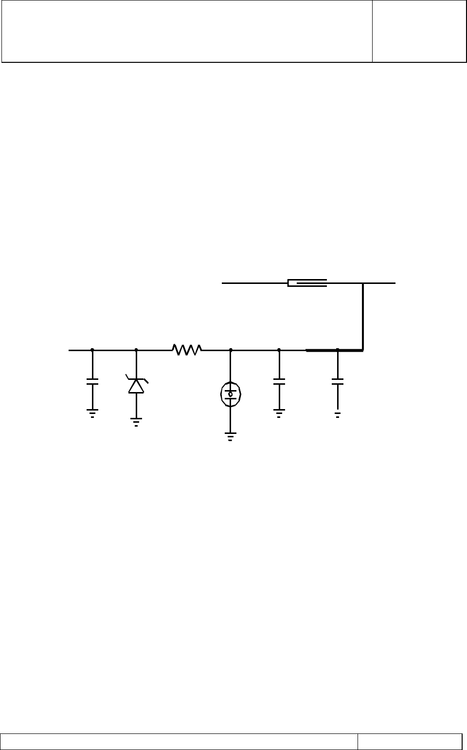
A Schematic of the Lightning Protection Circuit is shown in Figure 16.
2.3.4 Schematic of Lightning Protection circuit.
Figure 16 A Schematic of a Lightning Protection Circuit
2.3.5 Basic Grounding/Earthing: Good Practice
REMEC-Airtech has provided an Earth stud on your Masthead Amplifier ( MHA ) and can
supply a high conductivity cable to assist in this action. However, the efficacy of the
protection depends to a greater extent on the Grounding/Earthing arrangement of the rest
of the system than upon the REMEC-Airtech supplied cable.
CIRCUIT SCHEMATIC
TO THE DIPLEXER
(DC SHORT)
AIRLINE
DC BLOCKING CAP λ/4
DC
OUTPUT
TO
BTS

G3 MHA INSTALLATION AND
OPERATING MANUAL
00/OSM/0002
ISSUE 1
May 2000
REMEC-Airtech G3 Masthead Amplifier Installation and Operating Manual Page 36 of 59
It cannot be stated definitively which method of Grounding/Earthing must be used.
However, the following points of good practice should be considered:
• The structure of the mast, assuming it to be metal, should be bonded to Ground/Earth
Reference Potential. All legs of the mast and the Ground/Earth point of the BTS should
be bonded to this reference. The bonding should achieve a resistance of not more
than 0.1 Ohm between any two members.
• The resistance between the Mast top where the MHA is Grounded/Earthed and the
Ground/Earth Reference should be less than 1 Ohm. If this resistance value cannot be
achieved, a longer length of the type of cable which REMEC-Airtech has specified may
be used to run from the MHA Ground/Earth stud down to the Reference Earth.
• The maximum length of cable should be 50 metres and it should run closely alongside
the RF co-axial cable which goes to the MHA. In this way the inductance loop area
formed by (1) the RF cable screen and (2) the Ground/Earth cable, which might
intercept the lightning field, is reduced.
• The co-axial RF cable and the Ground/Earth cable should run down the central vertical
axis of the mast structure i.e. the Grounded/Earthed legs of the mast should form an
equidistant assembly around the vulnerable cables. This arrangement reasonably
simulates a Faraday screen to shield the cables.
More information on Grounding and Lightning Strikes can be found in the “Frequently Asked
Questions” Section of this manual.
2.4 Installation Measurements
2.4.1 A Method of measurement of Static Gain of the MHA
A technique of measuring the Static Gain of the MHA to ensure correct function of the unit
is given below.
The technique relies upon transmitting a signal (at about 0dBm) within the Rx band, from
the bottom of the feeder cable up through the un-powered MHA to one of the two Rx
antennae within a sector, and receiving this signal through the other antenna in the same
sector. This signal then returns to the BTS through the MHA and feeder RF cable and is
measured at this termination in the BTS.
With the MHA of the ‘receiving’ antenna turned off, the LNA is in bypass mode and a base-
line signal level is then received. When this MHA is supplied with DC power, the level of
this signal will increase due to the MHA amplifier gain by a value of nominally 12 dB (within
the limits of 11 to 13 dB) and the DC current drawn by the unit should be within
specification.
The ‘transmitting’ side and the ‘receiving’ side are exchanged to check the other MHA in the
sector.

G3 MHA INSTALLATION AND
OPERATING MANUAL
00/OSM/0002
ISSUE 1
May 2000
REMEC-Airtech G3 Masthead Amplifier Installation and Operating Manual Page 37 of 59
2.4.2 Effects of Cable Length on the Noise Figure
The Total System Noise Figure of a Base Station / Antenna system without an MHA
is, in dB:
Fsys = F2 + L1(Eqn 1)
where F2 = Base Station Noise Figure (assumed 6.5dB)
and L1 = Antenna RF feeder cable loss (assumed 2dB).
Hence the System Noise Figure is linearly increased as the RF feeder cable length
increases.
2.4.3 The effects of introducing REMEC-Airtech G3 MHA
If an MHA is introduced into the system, with an assumed Numerical Gain of 12dB, and a
Noise Figure of 1.8dB, the overall System Noise figure is heavily dependent on the MHA
Noise figure F1 (from Friis Law):
In Noise Factor terms Fsys = F1 +((F2 x L1) -1 ) (Eqn 2)
G1
where F1 = MHA Noise Factor
and G1 = MHA Gain
F2 = BTS Noise Factor
and the System Noise Figure Fsys(dB) = 10 Log10( Fsys ) (Eqn 3)
or Fsys(dB) = 10 log10 (Eqn 2)
It can be seen that as the value of L1 increases (i.e. a longer feed cable) the System Noise
Figure without an MHA increases linearly with L1, (Eqn 1), but that this has a smaller effect
on the System Noise Figure, Fsys with an MHA (Eqn 2) because it is a second order effect
in Eqn 2. The Whole System Sensitivity is linearly dependent upon the System Noise
Figure in both cases. The greater the Noise Figure, the worse the Sensitivity. Hence the
MHA which reduces the Overall System Noise improves the Base Station Sensitivity,
particularly systems with high feeder losses. In tabular form, showing the effect of
increasing feeder cable losses is as follows:

G3 MHA INSTALLATION AND
OPERATING MANUAL
00/OSM/0002
ISSUE 1
May 2000
REMEC-Airtech G3 Masthead Amplifier Installation and Operating Manual Page 38 of 59
L1Without REMEC-Airtech
MHA With REMEC-Airtech MHA Improvement
Cable Loss
(dB)
System Noise
Figure
System
Sensitivity (dBm)
System Noise
Figure
System
Sensitivity (dBm)
in Sensitivity
(dB)
04.5 -108.5 2.12 -110.87 2.37
15.5 -107.5 2.24 -110.72 3.22
26.5 -106.5 2.39 -110.68 4.18
37.5 -105.5 2.57 -110.42 4.92
48.5 -104.5 2.78 -110.20 5.70
59.5 -103.5 3.04 -109.95 6.45
Expected Typical Value of L1 .
2.4.4 The Effect of Auxiliary attenuator in the Rx path
In order to meet the ETSI 11.21 requirements in the presence of strong interfering signals
in the uplink with some type of BTSs, it may be necessary to insert an attenuator in the
antenna line (feeder cable) between the MHA’s BTS port and the Antenna port of the BTS.
The procedure to calculate the value of the required attenuator in is given in the following
section.
2.4.4.1 Establishing the Optimal Attenuator with No MHA fitted
The addition of attenuator in the uplink Rx path can be used to adjust the total gain for
optimal dynamic range at the BTS Receiver input.
The attenuation should be adjusted to give a total path loss of 6 dB in the uplink (receive)
path which should include the loss in the RF feeder line already in position in any particular
installation. As this feeder loss will vary between different installations due to the length
and type of the RF feeder cable, the loss should be measured and the best match of
attenuator determined.
The technique for establishing the best attenuator is to measure the open-circuit Return
Loss of the antennae system from the BTS using a Network Analyser. This figure
represents the loss from the BTS up to Antenna and back, and so is numerically twice the
feeder loss.
After the measured Return Loss has been divided by two, a figure of the order of 2dB
should be found for the RF feeder loss.
Subtracting this from the ideal 6dB total path loss gives the value of the required
attenuator.
*
*

G3 MHA INSTALLATION AND
OPERATING MANUAL
00/OSM/0002
ISSUE 1
May 2000
REMEC-Airtech G3 Masthead Amplifier Installation and Operating Manual Page 39 of 59
After fitting the attenuator, the Return Loss match measured should then be 12dB, which is
the ideal figure for optimal performance.
2.4.4.2 Establishing the Optimal Attenuator with REMEC-Airtech MHA fitted
The addition of attenuators in the uplink Rx path can adjust the total gain for optimal
dynamic range at the BTS Receiver input. For the assessment and setting of the ideal
attenuator, the MHA should be powered off, so that it is in bypass mode.
The attenuation should be adjusted to give a total path loss of 8dB, and this should include
the loss in the RF feeder line already in position in any particular installation plus the
additional 2dB though the MHA. As this feeder loss will vary between different installations
due to the length and type of the RF feeder cable, the loss should be measured and the
best match of attenuator determined.
The technique for establishing the best attenuator value is to measure the open-circuit
Return Loss of the antennae system from the BTS using a Network Analyser. This figure
represents the loss from the BTS up through the MHA in bypass mode to Antenna and
back, and so is numerically twice the feeder loss.
After the measured Return Loss has been divided by two, a figure of the order of 4dB
should be found for the total feeder loss.
Subtracting this from the ideal 8dB total path loss gives the value of the optimal attenuator.
After fitting the attenuator, the Return Loss match measured should then be 16dB, which is
the ideal figure for optimal performance for a system that includes an MHA.

G3 MHA INSTALLATION AND
OPERATING MANUAL
00/OSM/0002
ISSUE 1
May 2000
REMEC-Airtech G3 Masthead Amplifier Installation and Operating Manual Page 40 of 59
3 Operation and Maintenance
3.1.1 Set-up and Test
a) Ensure that the PDU supply and each alarm enable and output enable switch is set to
the off position.
b) Switch on the PDU circuit breaker at the Supply distribution board.
Note: Should the circuit breaker trip do not attempt to reset.
c) Check all installation wiring for correctness before proceeding.
d) Switch ON the PDU power switch. Ensure that the power on lamp illuminates Green
and that the two dc-dc converter ‘healthy’ lamps illuminate Green. This indicates
correct operation of the PDU and the two dc-dc converter assemblies.
e) At the PDU switch on each of the alarm enable lines and ensure that its associated
output indicator LED illuminates Red to indicate a low current alarm.
f) Switch on each MHA output enable switches one at a time. DO NOT SWITCH ALL
SWITCHES TOGETHER. Ensure that each output indicator LED changes from Red to
Green as each output is enabled.
Note: Should the indicator remain Red, refer to Section 3.1.2 for fault finding procedures.
g) When all MHAs have been switched ON, all the output indicators should be illuminated
Green.
h) Contact the Network Management Centre and ensure that the BTS alarm reporting
system indicates correct operation of the MHA system. This confirms correct
operation of all MHA’s and the PDU.
i) The installation is ready for performance testing.
3.1.2 Fault Finding and Repair Procedures
The instructions given in the followings sections should be followed to carry our preliminary
checks to identify and rectify any faults for normal operation of the MHA. If the problem still
continues, the integrity of the feeder and thus the DC continuity between the MHA should
be checked using the REMEC Airtech Test Kit available as an optional accessory. The
description of the Test kit and the test procedures are detailed in Section 3.1.3 of this
document.
3.1.2.1 No indication on PDU
When the PDU is switched on, the power ON and dc-dc converter LEDs will illuminate to
show that each of these circuits is functioning satisfactorily. Should there not be a supply
ON indication perform the following circuit tests:

G3 MHA INSTALLATION AND
OPERATING MANUAL
00/OSM/0002
ISSUE 1
May 2000
REMEC-Airtech G3 Masthead Amplifier Installation and Operating Manual Page 41 of 59
a) Ensure that the DC supply is available and that the PDU circuit breaker is switched on
at the distribution board.
b) Ensure that the power input connector is plugged into the PDU power connection.
Using a multi-meter, ensure that -48V is available on pin 4 with respect to pin 3 of this
connector.
c) If the supply input is available at the connection to the PDU, the PDU supply input fuse
should be checked.
Note: This fuse will fail if an incorrect polarity is connected to the PDU supply input.
d) If the fuse has failed ensure that the PDU supply is correct before refitting a
replacement 1 Amp fuse (slow blow type).
e) If either of the dc-dc converter healthy lamps is extinguished, the dc-dc converter
assembly may be producing a voltage outside its normal operating range. Remove
the two thumb screws from the front panel assembly to gain access to the dc-dc
converter modules. Ensure that each assembly is pushed securely into its mating
connector. Remove the fuse from the faulty assembly and ensure that the fuse is
intact. If the fuse has failed, replace it with a 0.5 Amp fuse (slow blow type). Should
the fuse fail again the dc-dc converter assembly is faulty and the PDU should be
replaced.
3.1.2.2 No PDU indication on supply output indicators
a) Each PDU 12V output and alarm can be disabled by the use of DIP switches on the
front of the equipment. If any of the supply output indicators are not illuminated either
Red or Green and remain Extinguished, the probable cause is the Alarm enable switch
being set to the Disable position. When the Alarm switch is switched to the Enable
position the LED indicator should illuminate Green or Red.
b) If the Status LED fails to illuminate when the output enable switch has been set to
enable the PDU is faulty and should be replaced.
c) If all Output Indicators are Extinguished the probable cause of the failure is the lack of
12V supply. Check the PDU indications as detailed in Section 3.1.1.
3.1.2.3 PDU output status indicators illuminated red
Each PDU output has current sensing to ensure that the MHA is operating within the
correct current window. The Output Indicator will illuminate Green indicatiing that the MHA
is operating within the normal operating current window specified in the MHA Product
Description. The PDU has alarm indications for over/under current consumption by the
MHA. The Output Indicator will illuminate Red indicating a failure. Should an output
indicator illuminate Red, proceed as follows:
a) Ensure that the associated PDU output enable switch is switched Enable to provide
power to the MHA.

G3 MHA INSTALLATION AND
OPERATING MANUAL
00/OSM/0002
ISSUE 1
May 2000
REMEC-Airtech G3 Masthead Amplifier Installation and Operating Manual Page 42 of 59
b) Remove the MHA output fuse associated with the faulty output and ensure that the
fuse is intact. A fuse failure will result in zero current which will give a low current
alarm. If fuse is found to be open circuit replace with a 0.5 Amp (quick blow type).
c) Should the replacement fuse fail, the cause is probably due to a short circuit between
the inner and outer connections of the MHA supply feed or a failure of the Bias Tee. All
connections should be checked for a short between the inner and outer.
d) If the fuse is intact and the LED remains illuminated Red, the cause will be that the
MHA is drawing a current outside of the normal operating range. The MHA current can
be ascertained by connecting a digital multi-meter set to the highest current range
between the inner contact and the side contact of the MHA output fuse holder. The
nominal operating current should be as specified in the MHA Product Description. The
meter range can then be adjusted to display the operating current.
e) If the current exceeds the Alarm condition current given in the MHA Product
Description, the MHA is faulty and should be returned for replacement.
f) If, however, the output current indicates 0mA there is an open circuit in the supply
connection to the MHA. Possible causes are a damaged or open circuit cable or the
disconnection of RF cable assemblies between the MHA and the Bias Tee. The
power input connection to the Bias Tee should also be checked.
g) The integrity of the connection to the Bias Tee can be monitored using a digital multi-
meter. This should be connected to the ANT connector at the Bias Tee assembly with
the centre contact positive. The voltage available at this connector should be
approximately 12.25 V.
h) It should also be possible to measure +12.25V DC at the end of the power feed to the
BTS port of the MHA. If 12.25 V is available at the end of the BTS feeder cable to the
masthead amplifier with zero current flow and an alarm indication, the MHA assembly
has failed open circuit and should be returned for replacement.
3.1.3 MHA to Ground Equipment DC circuit Test
3.1.3.1 Introduction
The REMEC-Airtech Test Kit ‘D’ has been designed to provide the MHA installation teams
with a simple to operate confidence tool, which can be used to confirm the current drawn
by a MHA, and that the DC circuit between the BTS/PDU and the MHA is complete.
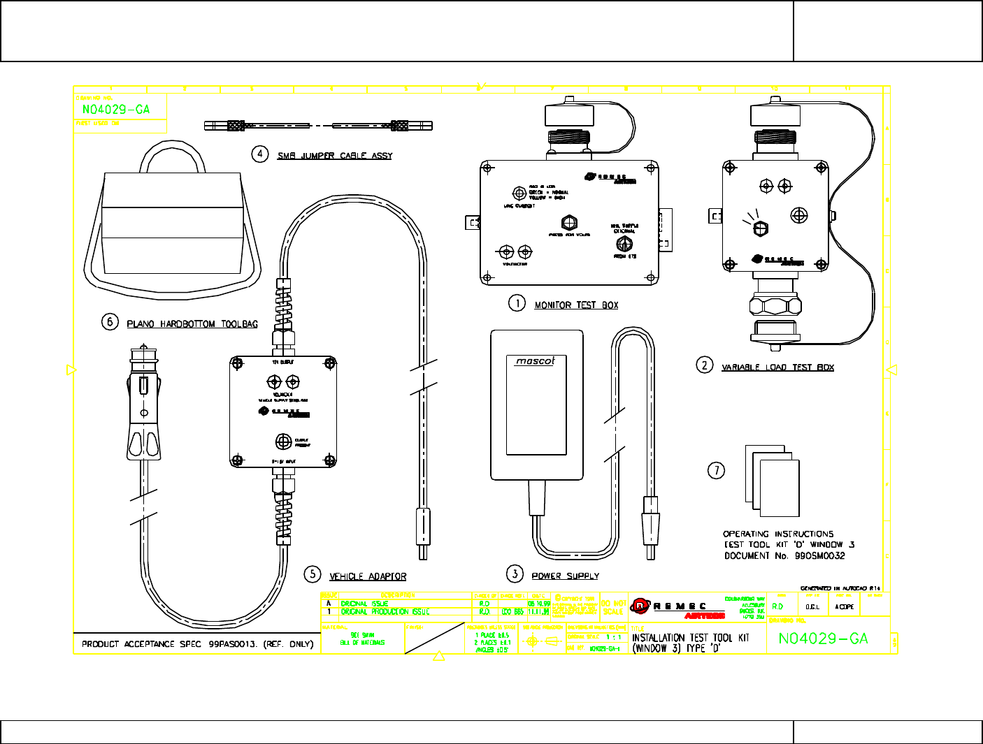
Test Kit ‘D’ comprises of four modules (shown in Figure 17 - Product Code N0402901):
Monitor Box
Variable Load
Wide Ranging Mains AC to 12 V DC Power Supply (Mascot)
Vehicle DC Adapter
The procedure described below uses Test Kit ‘D’ for MHAs with 75 to 140 mA normal
operating current.
G3 MHA INSTALLATION AND OPERATING MANUAL
00/OSM/0002
ISSUE 1
May 2000
REMEC-Airtech G3 Masthead Amplifier Installation and Operating Manual Page 43 of 59
Figure 17 DC Circuit Test Kit ‘D’
LOAD (mA)
NORMAL
LOW
HIGH SUPPLY
VOLTMETER
G3 MHA INSTALLATION AND
OPERATING MANUAL
00/OSM/0002
ISSUE 1
May 2000
REMEC-Airtech G3 Masthead Amplifier Installation and Operating Manual Page 44 of 59
3.1.3.2 Description
The Monitor Box is of a compact handheld design and is provided with both a 7/16 RF
connector and a protected SMB connector thus providing a flexiable facility for checking
installations with or without a Bias Tee installed. The Monitor Box can also be connected
to the BTS 12VDC supply providing a convenient method of checking the 12VDC output
from the BTS.
The Variable Load provides, during troubleshooting a convenient constant current source,
which has the provision for setting the current load to indicate to the BTS (or PDU)
high/low current alarm in addition to the normal current drawn by a serviceable MHA.
The Wide Ranging Mains Power Supply (Mascot) converts the local AC mains to provide
the monitor box with a constant 12VDC supply. Additionally the flexibility of the Test Kit has
been maintained by having a device, which can be used globally.
The Vehicle DC Adapter provides an alternative 12VDC source for use where there is no
mains available.
The following additional equipment is also required
Digital Multimeter
IEC Mains Cable
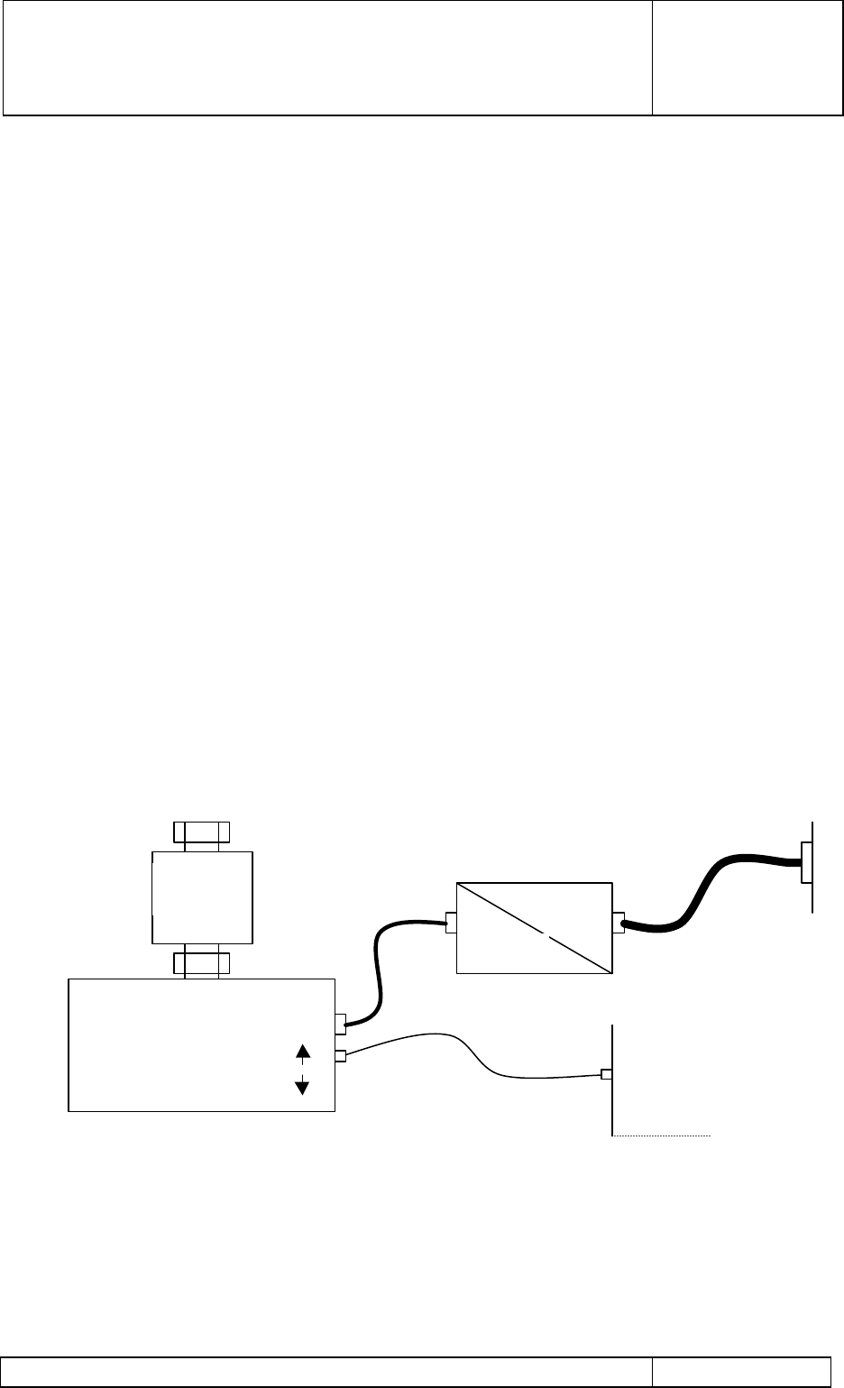
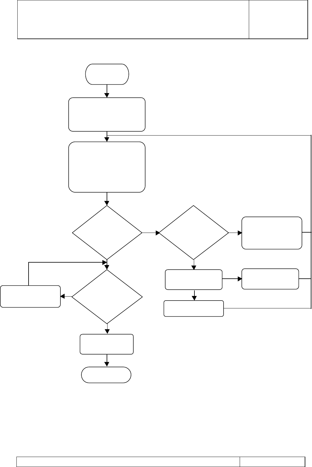
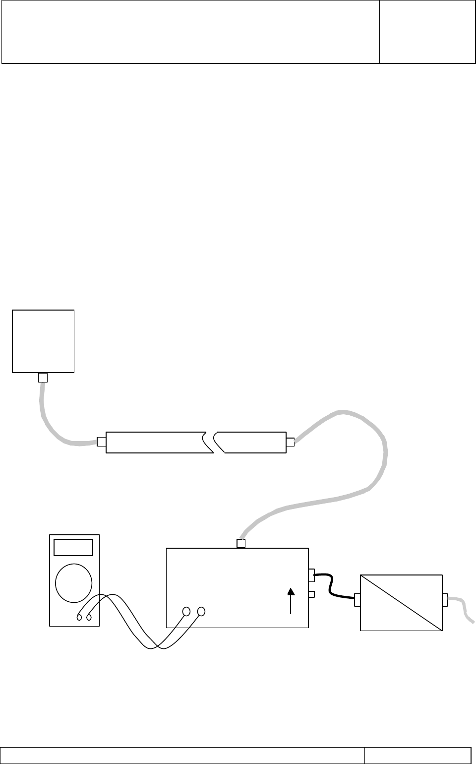
3.1.3.3 Test Kit D confidence test
It is advisable to check the function of the test kit prior to carrying out any measurements.
To achieve this follow flow chart 1 in Figure 19:
Figure 18 Test Kit Configuration during confidence test
MONITOR
EXTERNAL
From BTS
ac
+12V
BTS (or
PDU)
SMB – SMB TEST CABLE
VARIABLE
LOAD
G3 MHA INSTALLATION AND
OPERATING MANUAL
00/OSM/0002
ISSUE 1
May 2000
REMEC-Airtech G3 Masthead Amplifier Installation and Operating Manual Page 45 of 59
Figure 19 Flow Chart 1 ~ Test Kit D confidence test
YES
YES
YES
NONO
START
WITH THE TEST KIT CONFIGURED
AS PER FIGURE 1.
SELECT “FROM BTS” ON THE
MONITOR BOX
ON THE VARIABLE LOAD BOX,
SELECT IN TURN:
LOW, NORMAL, HIGH
ON THE MONITOR BOX, THE LAMP
INDICATES :
RED, GREEN, YELLOW
WERE THE
INDICATIONS
CORRECT
IS THE BTS
ALARM
WINDOW
75 – 140
mA
REPLACE THE TEST KIT
WITH THE CORRECT
ALARM WINDOW
KIT
1. FAULT IN BTS
2.
FAULTY TEST
1. CLEAR BTS
FAULT
2.
REPLACE THE
KIT
DOES BTS
STATUS =
LOAD STATES
BTS & TEST KIT
CORRECT
END
CORRECT THE BTS
REPORTING STATUS
G3 MHA INSTALLATION AND
OPERATING MANUAL
00/OSM/0002
ISSUE 1
May 2000
REMEC-Airtech G3 Masthead Amplifier Installation and Operating Manual Page 46 of 59
3.1.3.4 Checking the operating current of the MHA.
After having installed the complete antenna system including the MHA, the operating
current of the MHA can be checked. The Test Kit also provides a facility to check the
operating current during various points of the installation.
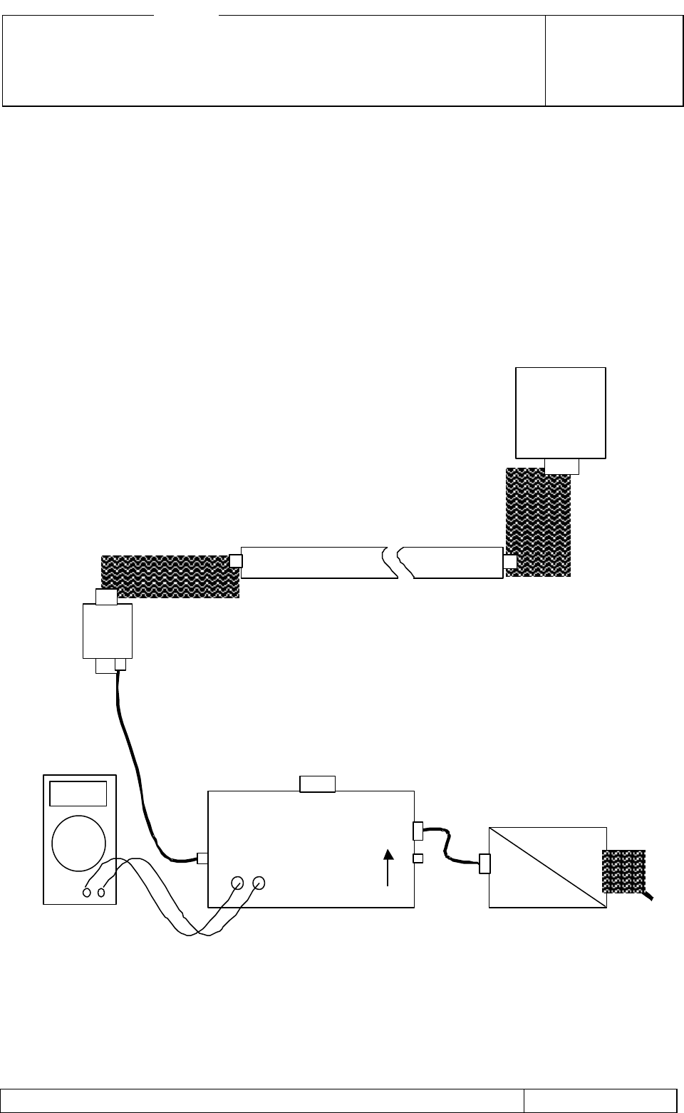
3.1.3.4.1 Checking the operating current when neither the Bias Tee nor BTS are
present.
With the Test Kit configured as in Figure 20, select the MHA supply to External. The lamp
on the monitor box indicates “GREEN” if the operating current is satisfactory. If any other
indication is displayed then follow the “trouble shooting” guide.
To check the actual operating current connect a Digital Multimeter set to the 0.5 volt range,
to the test points of the monitor box, record the reading on the Digital Multimeter. Millivolts
displayed on the multimeter equate to milliamps.
Figure 20 Operating Current Test for a System without Bias Tee or BTS
+12V
MHA
MONITOR
EXTERNAL
FEEDER
ac
G3 MHA INSTALLATION AND
OPERATING MANUAL
00/OSM/0002
ISSUE 1
May 2000
REMEC-Airtech G3 Masthead Amplifier Installation and Operating Manual Page 47 of 59
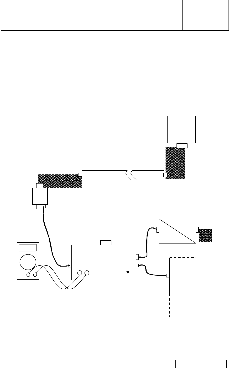
3.1.3.4.2 Checking the operating current when a Bias Tee is connected and the
BTS is not present.
With the Test Kit configured as in Figure 21, select the MHA supply to External. The lamp
on the monitor box indicates “GREEN” if the operating current is satisfactory. If any other
indication is displayed then follow the “trouble shooting” guide.
To check the actual operating current connect a Digital Multimeter set to the 0.5 volt range,
to the test points of the monitor box, record the reading on the Digital Multimeter. Millivolts
displayed on the multimeter equate to milliamps.
Figure 21 Operating Current Test for a System with a Bias Tee but without a BTS
Cable
ac
+12V
MONITOR
BOX
EXTERNAL
MHA
FEEDER
BIAS TEE
System
Cable
G3 MHA INSTALLATION AND
OPERATING MANUAL
00/OSM/0002
ISSUE 1
May 2000
REMEC-Airtech G3 Masthead Amplifier Installation and Operating Manual Page 48 of 59
3.1.3.4.3 Checking the operating current when a Bias Tee is connected and the
BTS is present.
With the Test Kit configured as in Figure 22, select the MHA supply to External. The lamp
on the monitor box indicates “GREEN” if the operating current is satisfactory. If any other
indication is displayed then follow the “trouble shooting” guide.
To check the actual operating current then connect a Digital Multimeter set to the 0.5 volt
range, to the test points of the monitor box, record the reading on the Digital Multimeter..
Millivolts displayed on the multimeter equate to milliamps.
Figure 22 Operating Current Test for a System with a Bias Tee and BTS
connected
FEEDE
R
BIAS TEE
ac
+12V
MONITOR
BOX
BTS
MHA
BTS
System
cable

G3 MHA INSTALLATION AND
OPERATING MANUAL
00/OSM/0002
ISSUE 1
May 2000
REMEC-Airtech G3 Masthead Amplifier Installation and Operating Manual Page 49 of 59
4 Variable Gain MHA Option
REMEC Airtech Variable Gain MHAs provide either 7 to 22 dB (PCN 1800 and PCS 1900
MHAs) or 2 to 12 dB (GSM 900 MHAs) gain range. The system operation is similar to that
of the Fixed Gain described in Section 1.1.1 of this document. The DC power is provided
by a PDU located near the BTS. The ‘Set and Forget’ gain of the MHA is set remotely
using a ground level equipment. The system utilises Bias Tees to provide DC supply to
the MHA and transmit serial data ‘Antenna Line Protocol’ (ATP) between the ground level
gain setting and monitoring equipment and the tower top MHA.
In addition to the PDU and Bias Tees described in Section 1.1.1 for a site of six fixed gain
MHAs, the Variable Gain MHA system requires the following to enable Gain setting and
status monitoring:
• Antenna Line Protocol Modem – supplied by REMEC Airtech
• A suitable Laptop Personal Computer (PC) – supplied by the customer
• A Compact Disc containing software for the PC – supplied by REMEC Airtech to be
installed in the Laptop PC
• An extra interconnecting cable – supplied by REMEC Airtech
This additional hardware and the Variable Gain MHA are described in the following
sections.
4.1 Hardware Description
4.1.1 Variable Gain Masthead Amplifier
This description of the supplied Variable Gain Masthead Amplifier is applicable to the
following GSM 900, PCN 1800 and PCS 1900 products:
• A GSM 900 MHA with a 2 dB to 12 dB gain range settable in 1 dB steps.
• A PCN 1800 MHA with a 7 dB to 22 dB gain range settable in 1 dB steps
• A PCS 1900 MHA with a 7 dB to 22 dB gain range settable in 1 dB steps
The above Variable Gain G3 Masthead low noise amplifier provide adequate gain to the
receive signal to improve system sensitivity and increase the receive coverage to match
the transmit area. These products are variants of G3 MHA described in Section 1.2.1 of
this document and use the same duplexing and filtering technology except for the Low
Noise Amplifier tile.
The MHA filter configuration is that of a triplexer. A Tx filter is diplexed at both ends to two
Rx filters. A low noise amplifier (LNA) is placed between the two Rx filters in such a way
that eliminates interconnecting cables and thus optimises noise figures.

G3 MHA INSTALLATION AND
OPERATING MANUAL
00/OSM/0002
ISSUE 1
May 2000
REMEC-Airtech G3 Masthead Amplifier Installation and Operating Manual Page 50 of 59
The LNA block comprises a balanced amplifier configuration using GaAs FETs followed by
a MMIC module. The LNA also incorporates a PIN diode bypass switch with very low
insertion loss. This low insertion loss bypass link is switched in, should:-
a) the DC supply fail
or
b) a fault is detected within the amplifier circuit itself .
An integrated planar Low Pass Filter (LPF) is also positioned immediately behind the
amplifier to filter the bandpass re-resonance out of band frequencies ensuring the overall
system MHA filter rejection specifications are met up to 13 GHz.
The MHA is housed in a weatherproofed enclosure rated to IP68. 7/16 RF connectors
provide interface to both the ANT and BTS ports of the unit. This enables the MHA to be
mounted in line with the ANT and BTS jumper cables. An earthing stud is mounted on one
end next to the BTS connector for earthing the MHA to the mast.
LNA ARCHITECTURE
The LNA tile provides a system receive gain of 7 to 22 dB (or 2 to 12 dB) in 1 dB steps. It
consists of a two stage amplifier section followed by a digital attenuator and a low pass
filter. It also incorporate a bypass switch designed to provide a low insertion loss link in the
receive path in the case of a FET failure, or if the second stage fails.
The DC power is transmitted to the MHA unit via the RF feeder cable using Bias Tees to
couple the DC power onto the RF cables.
The LNA tile incorporates a BITE circuit to monitor the status of the FET and MMIC
amplifier devices and report failure to the Personnel Computer (or the PDU) utilising a
serial communications interface modulated onto the RF feeder cable. The 4-bit word
selecting the receive gain is set from a PC and the Antenna Line Protocol Modem using
the serial interface
The interface drawings shown in Figure 3 and Figure 15 are applicable to the VGMHA.
4.1.2 Power Distribution Unit
The VGMHA requires Power Distribution Unit described in Sections 1.1.2.2 and 1.2.2 to
provide DC power, and alarm functions in case of VGMHA failure.
4.1.3 Bias Tee
The Bias Tee required to provide DC power and transmit the serial data is described in
sections 1.1.2.3 and 1.2.3
4.1.4 Cable Kit
The cable kit required to connect the system is described in sections 1.1.2.4 and 1.2.4.
Cables required to connect the Antenna Line Protocol (ALP) Modem to the Bias Tee and a
Laptop PC to ALP Modem are supplied with the ALP modem kit.
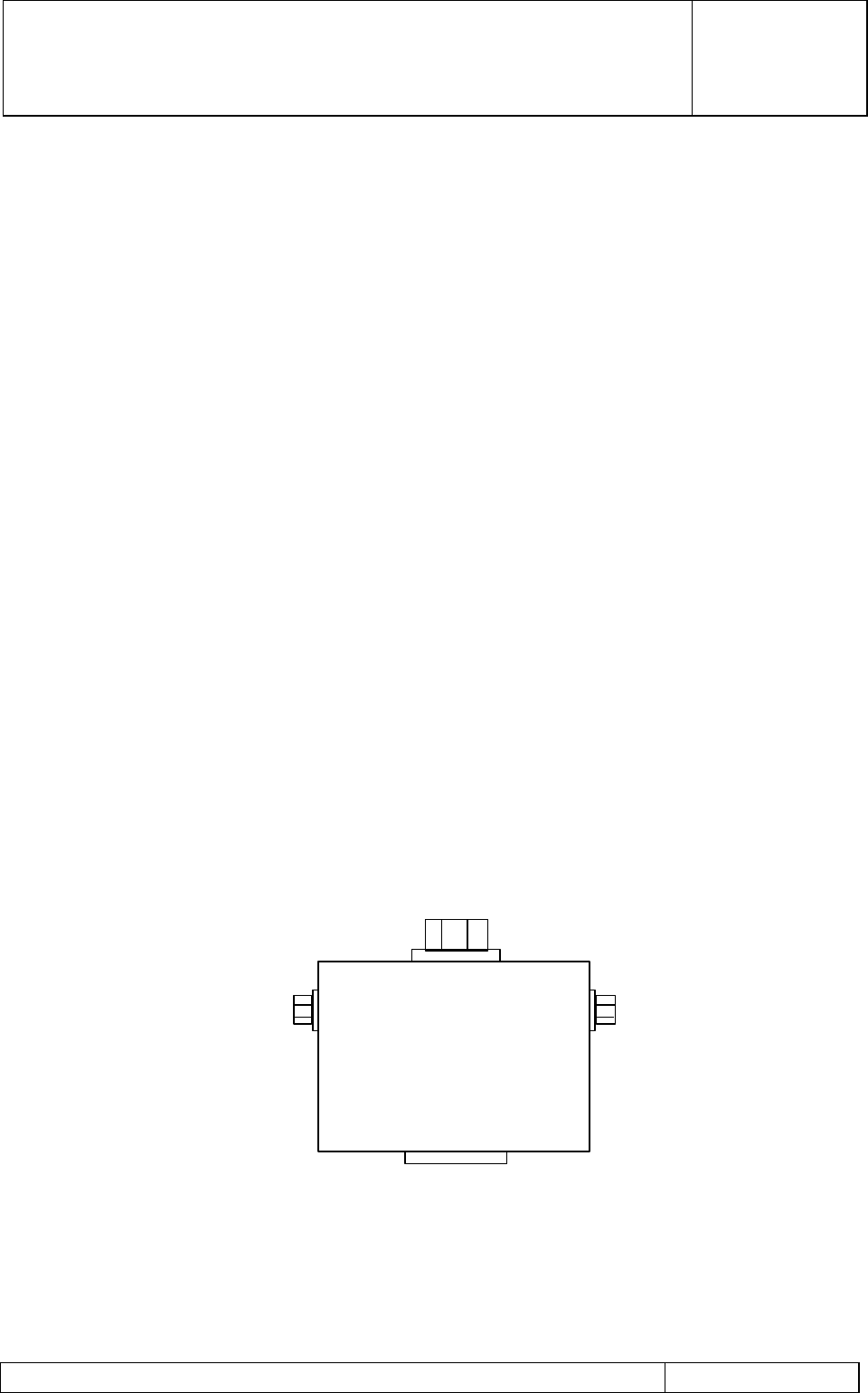
G3 MHA INSTALLATION AND
OPERATING MANUAL
00/OSM/0002
ISSUE 1
May 2000
REMEC-Airtech G3 Masthead Amplifier Installation and Operating Manual Page 51 of 59
4.1.5 Mounting Kit
The mounting kit required to install the VGMHA on a flat surface or a pole is described in
sections 1.1.2.5 and 1.2.5
4.1.6 Antenna Line Protocol Modem Kit
The Antenna Line Protocol Kit (Product Code N26001) consists of;
• Antenna Line Protocol Modem
• External AC to 12 V DC power supply (Mascot – included in DC Circuit Test Kit ‘D’
Figure 17)
• A RS232 interface cable with 9 pin D connectors on both ends
• A coaxial cable with SMB connectors on both ends
• A Gain Setting program Compact Disk.
Note: A suitable Laptop Personal Computer must be supplied by the customer.
This must have at least Windows 98 operating system
4.1.6.1 Antenna Line Protocol Modem
The Antenna Line Protocol (ALP) Modem provides the means of communicating to the
Variable Gain Masthead Amplifier. The control of gain is accomplished by coded signal
(serial data) applied, together with DC power to the MHA BTS input via the RF feeder
cable. The ALP Modem provides the modulator (demodulator) for the serial data signals,
which are imposed upon the DC supply. The DC supply is applied to the ALP Modem from
an external mains to 12 V DCsupply. The serial data gain control and monitoring signals
are transmitted via an RS232 interface from a Laptop Computer to the ALP Modem.
Figure 23 Antenna Line Protocol Modem
ANTENNA LINE PROTOCOL
MODEM
Modulates and Demodulates
Data from a Laptop PC onto
12 Volt DC supply for the MHA
Alternative connection to Tower Top MHA.
Direct connection to RF feeder.
12V DC and Serial Data Signal
Connection to Tower Top MHA
Via Bias Tee in the RF feeder.
12V DC and Serial Data Signal
7/16”
SMB
Male 2.1mm jack
centre pin
positive
12 V ± 0.5V
0.5 A max.
9 pin D plug
RS 232 interface
from Laptop PC

G3 MHA INSTALLATION AND
OPERATING MANUAL
00/OSM/0002
ISSUE 1
May 2000
REMEC-Airtech G3 Masthead Amplifier Installation and Operating Manual Page 52 of 59
4.1.6.2 Auxiliary 12 Volts Supply
The 12 Volt DC power supply is supplied with the ALP Modem kit. The 85 to 260 V AC
input is converted to 12 V DC ± 0.5 V at 0.5 Amps maximum. This unit provides DC power
to the Modem and to the tower top VG MHA.
4.1.6.3 Gain Setting Program Compact Disc
A Compact Disc containing a software for a PC is provided with the kit. Follow the
instructions provided with the Compact Disc to install the Antenna Line Protocol program
in the Laptop PC. This program is used to provide two-way communication between the
Tower Top VG MHA and the Modem/PC on the ground.
4.2 Installation of Variable Gain MHA
The mechanical and electrical interfaces of the Variable Gain MHA are identical to that of
the Fixed Gain MHA. Follow the detailed installation instructions given in Section 2 to install
the Variable Gain MHA and connect it to the PDU via the Bias Tee.
4.3 Operation and Maintenance of Variable Gain MHA
Once the VG MHA system has been installed, follow the instruction given in Section 3 and
ensure that the MHA is operating satisfactorily and that no fault conditions are shown on
the PDU. Ensure that the LEDs on the PDU show green for the MHAs switched ON using
the output enable switches.
Having established that the VG MHA system is operating satisfactorily, follow the
instruction given in Section 4.3.1 below to adjust the gain of the MHA.
4.3.1 Gain Setting of the Variable Gain MHA
The set-up for the gain setting of the MHA is shown in Figure 25. Disconnect the normal
12 V DC supply from the PDU to the MHA at the SMB terminal of the Bias Tee. Using the
SMB to SMB cable supplied with the ALP Modem kit, connect the SMB terminal on the ALP
Modem to the SMB ‘DC’ terminal on the Bias Tee. Connect the 12 V auxiliary supply to the
2.1 mm Jack connector on the Modem. Connect the Laptop Personal Computer to the
ALP 9 pin D connector using the RS232 interface cable provided with the APL Modem kit.
Switch ON the auxiliary supply and the computer.
The Antenna Line Protocol is used to provide a two way communication facility between
the ground level equipment and the tower top Variable Gain MHA.:
• Ground to tower top:- RF gain setting, bypass operation.
• Tower top to ground:- Status information and fault reporting.
A ‘MHA Management Terminal’ window is displayed on the Laptop PC as shown in Figure
24. The right side of the window is used to set the required gain or bypass option. The left
side of the window reports the set gain, fault status and any DC power interrupts.
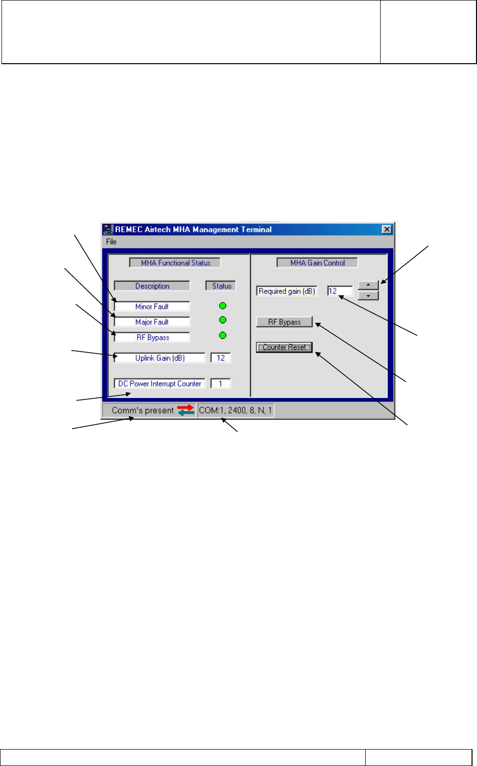
G3 MHA INSTALLATION AND
OPERATING MANUAL
00/OSM/0002
ISSUE 1
May 2000
REMEC-Airtech G3 Masthead Amplifier Installation and Operating Manual Page 53 of 59
Once the gain is set, the ALP model should be removed for use on other VG MHAs.
Disconnect the SMB to SMB cable at the Bias Tee and reconnect the output SMB from the
PDU. This restores the DC power and to the VG MHA and any fault conditions will be
displayed by the ‘alarm’ LEDs on the PDU. The summary alarm will be transmitted to the
BTS as for fixed gain MHAs. The above procedure may be used if further gain adjustment
is necessary.
Figure 24 MHA Management Terminal Window on Laptop PC
Up/Down RF
gain adjustment
Gain value sent
to tower top
Force MHA into
bypass mode
Reset DC interrupt
counter to zero
Comm port setting
ALP Connection status
Reduced RF
performance
‘soft fail’
RF fault ‘ hard fail’
Product in RF
bypass mode
Gain value
returned from
tower top
Intermittent
connection
monitor (0-255)
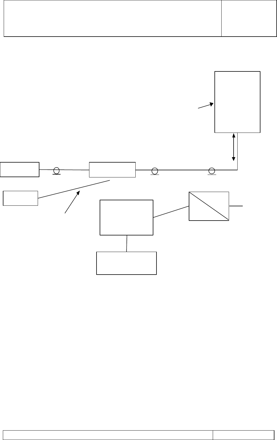
G3 MHA INSTALLATION AND
OPERATING MANUAL
00/OSM/0002
ISSUE 1
May 2000
REMEC-Airtech G3 Masthead Amplifier Installation and Operating Manual Page 54 of 59
Figure 25 MHA Gain Adjustment using ALP Modem and Laptop PC
BTS Bias Tee
Antenna Line
Protocol
MODEM
PDU
Normal connection to
provide 12 V DC to MHA.
Disconnect this and
connect ALP system to
adjust MHA Gain .
Reconnect PDU once
MHA Gain set
Variable
Gain
MHA
12 V DC and
ALP data
Incorporating ALP
modem and
microprocessor
control
Laptop
Personal Computer
RS232 interface
RF Feeder
Auxiliary 12Volt
supply
ac
+12VDC

G3 MHA INSTALLATION AND
OPERATING MANUAL
00/OSM/0002
ISSUE 1
May 2000
REMEC-Airtech G3 Masthead Amplifier Installation and Operating Manual Page 55 of 59
5 Frequently Asked Questions
5.1 Lightning Protection Circuit
General Background to Lightning Strikes.
Equipment installed on outdoor mast top environments is generally more vulnerable to
lightning strikes than surrounding ground base equipment. For this reason the MHA has
built-in circuitry to protect against such strikes which might otherwise cause permanent
damage to the system.
How does the lightning strike get to the MHA ?
A lightning strike hitting the top of the mast will cause an enormous current to flow from the
mast top down to ground - or the nearest 'ground' point. Along the way the current will take
the path of least resistance before finding 'ground'.
There are various types of couplings which can take place which can result in damage
being caused to electronic equipment during this process. However, the major threat to
the MHA unit is the result of these large currents travelling along the ground sheath of the
RF cables connecting the BTS and ANT. The current on the ground sheath is transformed
into a high voltage appearing on the inner conductor. This occurs as a result of a
parameter known as 'transfer resistance effect' of the cable. It is this inner voltage and
current which is potentially the most harmful to electronic equipment.
What forms of protection does the MHA use?
The ANT port is designed to intrinsically provide excellent protection against lightning due
to the construction of the internal coaxial filters. Since the antenna port feed is tapped
directly onto each first stage filter resonator the unit offers a very low resistance path to
ground at lightning frequencies (the frequency band of a typical lightning strike is 3KHz to
100KHz).
The BTS port protection is slightly different. The diagram below shows the circuit
schematic of the bias tee/lightning protection scheme used inside the mast head amplifier.
Is there any maintenance required on an MHA?
The REMEC-Airtech MHA is a sealed-for-life unit and the only checking required is for
mechanical integrity of the mounting and jumper connections to check for tightness. There
is no scheduled maintenance for the internal components.
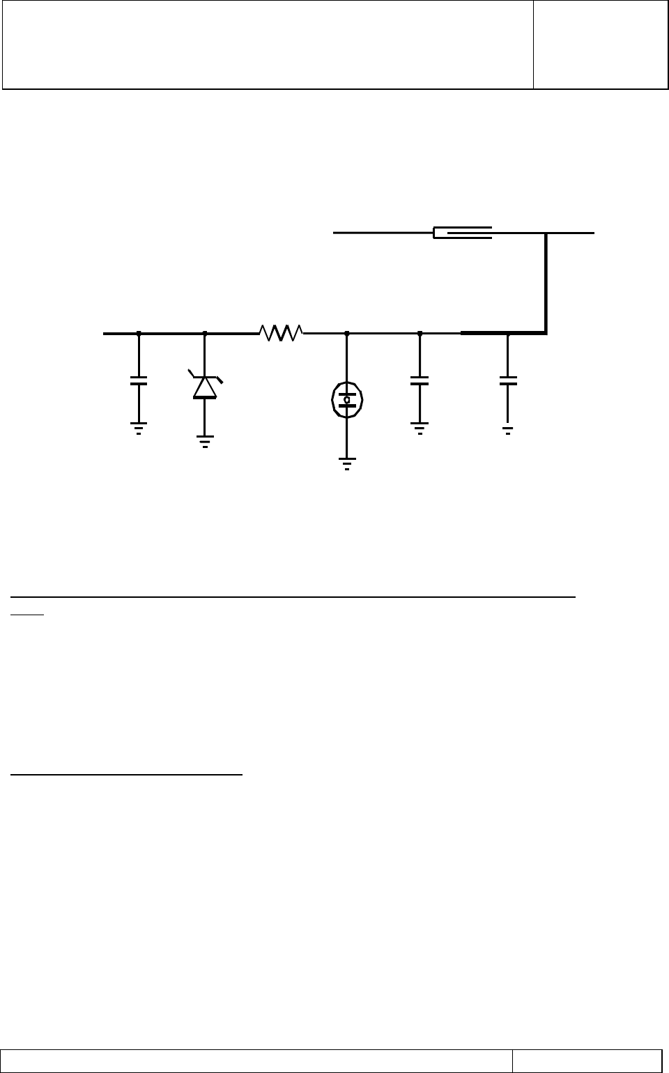
G3 MHA INSTALLATION AND
OPERATING MANUAL
00/OSM/0002
ISSUE 1
May 2000
REMEC-Airtech G3 Masthead Amplifier Installation and Operating Manual Page 56 of 59
Two important devices known as a ‘gas discharge tube’ and a ‘transorb suppresser’ are
used to short the dc line to the low noise amplifier (LNA) to ground. This circuit is designed
to respond quickly to high voltage/current bursts preventing the destructive voltage levels
from reaching the LNA.
What level of lightning specification has the REMEC-Airtech MHA been designed to
meet?
The REMEC-Airtech G3 MHA has been designed to handle test cases based on
international standard IEC 1312-1 (Protection against Lightning Strike into Information
Equipment on Buildings) with no damage to their functionality.
The unit has been subjected to the following limits at an approved lightning test house and
continued to function normally after a single strike simulation hit.
Understanding the wave-form data:
The graph below illustrates how this wave-form data is interpreted. The 10 in 10/350µsec
refers to the rise time of the pulse. This time is for the difference between the 90% and
10% limits as shown on the graph. Similarly, the 350µsec is the time taken for the wave-
form to reach 50% of its maximum limit.
CIRCUIT SCHEMATIC
TO THE DIPLEXER
(DC SHORT)
AIRLINE
DC BLOCKING CAP λ/4
DC
OUTPUT
TO
BTS
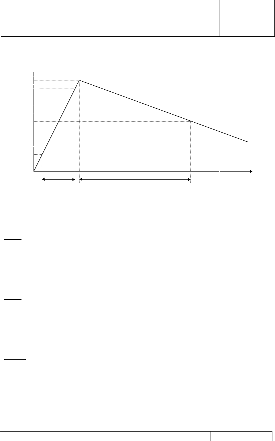
G3 MHA INSTALLATION AND
OPERATING MANUAL
00/OSM/0002
ISSUE 1
May 2000
REMEC-Airtech G3 Masthead Amplifier Installation and Operating Manual Page 57 of 59
Test 1
a) A 50kA current pulse of wave-form 10/350µsec is applied to the outer conductor of the
antenna 'ANT' port.
b) A 50kA current pulse of wave-form 10/350µsec is applied to the outer conductor of the
base transceiver station 'BTS' port.
Test 2
a) A 4kV voltage and 5kA current pulse of wave-form 10/350µsec is applied to the 'ANT'
port.
b) A 4kV voltage and 2.5kA current pulse of wave-form 10/350µsec is applied to the 'BTS'
port.
NOTE: REMEC-Airtech can also provide as an option lightning protection to
meet IEC 801-5, pulse shape 8/20 µSec at 20kAmps.
100%
90%
50%
10%
Peak Value
LIGHTNING WAVEFORM DIAGRAM.
10 µSec.
Rise
350 µSec.
Fall
Time
kA

G3 MHA INSTALLATION AND
OPERATING MANUAL
00/OSM/0002
ISSUE 1
May 2000
REMEC-Airtech G3 Masthead Amplifier Installation and Operating Manual Page 58 of 59
5.2 Mounting and Maintenance
Why do REMEC-Airtech recommend Teracom connector be used on jumpers?
The Teracom connectors have an integral o-ring seal to the outer of the jumper cable
and therefore do not need additional protection in the form of conformal sealing tape over-
wrapped after connections have been made. This makes for a reliable installation. Some
Network Operators and Installation teams do choose to fit additional protection, however,
and in doing so no damage will be done to the MHA.
Why can the MHA be mounted in any orientation?
The REMEC-Airtech G3 MHA is unique in that it is designed and packaged to a full IP68
rating. Both the MHA enclosure and the 7/16 connectors have been specially designed to
be fully water submersible and therefore the unit does not rely on drain holes or other
devices to protect the internal components. As a result the REMEC-Airtech MHA may be
mounted in any orientation. No other competitive product has this form of protection and,
while they have to be mounted in a certain way in order to minimise water and water
vapour penetration, those other units cannot be guaranteed to remain serviceable in
severe weather conditions. The REMEC-Airtech unit is virtually totally protected against
the environment.
Can the MHA be mounted horizontally?
The REMEC-Airtech MHA can be mounted in any orientation to suit the particular logistics
of any site. Ensure that it is not mounted where it can be used as a foothold. See Figure
11 for recommended mounting configurations.
Why is the MHA fitted up the mast?
The Rx signal received from the mobile unit is a very low level signal. There is additional
loss of this signal in the feeder cable from the antenna down to the Base Station. As the
signal level is diminished, the effect of the signal noise becomes a greater and greater
proportion of the Receive signal, thereby limiting the sensitivity of the Base Station. By
amplifying the signal as near to the antenna as practical, the effect of the feeder cable loss
is minimised and the sensitivity of the Base Station is improved.

G3 MHA INSTALLATION AND
OPERATING MANUAL
00/OSM/0002
ISSUE 1
May 2000
REMEC-Airtech G3 Masthead Amplifier Installation and Operating Manual Page 59 of 59
6 Glossary
AC Alternating Current
ALP Antenna Line Protocol
ANT Antenna
BBU Battery Backup Unit
BITE Built In Test Equipment
BTS Base Transceiver Station
DC Direct Current
DCS Digital Communication System
LED Light Emitting Diode
MHA Masthead Amplifier
PDU Power Distribution Unit
RF Radio Frequency
Rx Receiver
BT Bias Tee
TBD To Be Determined
Tx Transmitter