Powerwave Technologies KRB1011108 Multi Carrier Power Amplifier User Manual MCPS Subsystem Manual
Powerwave Technologies, Inc. Multi Carrier Power Amplifier MCPS Subsystem Manual
Contents
- 1. User Manual
- 2. QANKRB1011108 User Information
QANKRB1011108 User Information
ERICSSON AMPLIFIER TECHNOLOGIES INC.
49 Wireless Boulevard
Hauppauge, New York 11788
(631) 357-8200
MCPA SUBSYSTEM
ASSEMBLY
Product Number KRB 101 1108
INSTALLATION OPERATION AND
MAINTENANCE INSTRUCTIONS
Ericsson Amplifier Technologies Inc.
Technical Publication SCA
Revision A
PREPARED
May 29, 2001
NOTICE
PROPRIETARY AND PRIVATE
The information contained in this document is the property of Ericsson
Amplifier Technologies Inc., (Company) and shall be kept in strict confidence.
Except with the written permission of the Company, such information shall not
be published, or disclosed to others, or used for manufacture or sale or for
any other purpose. This document shall not be duplicated in whole or in part.
Any recipient so agrees by acceptance of this document.
© 2001 – Ericsson Amplifier Technologies Inc. i
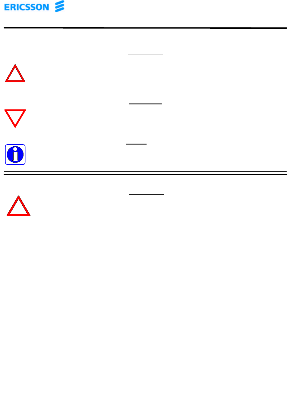
The following symbols are used throughout this technical manual:
WARNING
THIS SYMBOL INDICATES IMPORTANT INFORMATION THAT IS
EMPHASIZED TO ALERT THE READER TO THE POTENTIAL RISK OF
PERSONAL INJURY TO THE OPERATOR OR OTHER PERSONNEL.
CAUTION
This symbol indicates important information that is emphasized to alert
the reader to the potential risk of damage to the amplifier.
NOTE
This symbol indicates information that is highlighted signifying an
operation or procedural step requiring additional emphasis.
Ericsson Amplifier Technologies Incorporated, provides this technical manual “as is”
without warranty of any kind, either expressed or implied. Ericsson Amplifier
Technologies may make improvements or changes to the product and/or manual at any
time without notice.
Every effort has been made to ensure the accuracy and completeness of this technical
manual, however, it may contain technical inaccuracies or typographical errors.
Changes are made periodically to the information contained herein. These changes will
be incorporated into new editions of this technical manual.
Ericsson Amplifier Technologies is interested in receiving comments from the users of this
manual in order to improve its usefulness. All comments should be directed through
regular mail to the address listed on the title page of this manual. Ericsson Amplifier
Technologies may use or distribute any of the information supplied in any way it believes
appropriate, without incurring any obligations.
All specifications are subject to change without notice.
WARNING
THE USE OF AN EARTH GROUND IS REQUIRED TO
ENSURE SAFETY.
IF THE EQUIPMENT APPEARS TO BE DAMAGED IN ANY
WAY, REMOVE ALL POWER TO THE UNIT, AND HAVE IT
SERVICED AS SOON AS POSSIBLE.
© 2001 – Ericsson Amplifier Technologies Inc. ii
WARRANTY
Unless otherwise specified, Ericsson Amplifier Technologies provides a Limited
Warranty of 12 months from the date of original shipment unless otherwise agreed to in
writing.
This warranty is void (1) if the equipment has been subject to unauthorized alteration,
modification or repair or, (2) due to defects or failures resulting from improper handling,
storage, operation, interconnection or installation; failure to continually provide a
suitable installation and operational environment; or any other cause beyond the range
of normal usage for the equipment (except, in all of the foregoing cases, when caused
by Ericsson Amplifier Technologies).
LIMITATION OF LIABILITY
In no event will Ericsson Amplifier Technologies be liable to customer or anyone else
for special collateral, exemplar, indirect, incidental or consequential damages, loss of
goodwill, loss of profits or revenues, loss of savings, loss of life, interruptions of
business, and claims of customers, whether such damages occur prior or subsequent
to or are alleged as a result of tortuous conduct, even if Ericsson Amplifier
Technologies has been advised of the possibility of such damages.
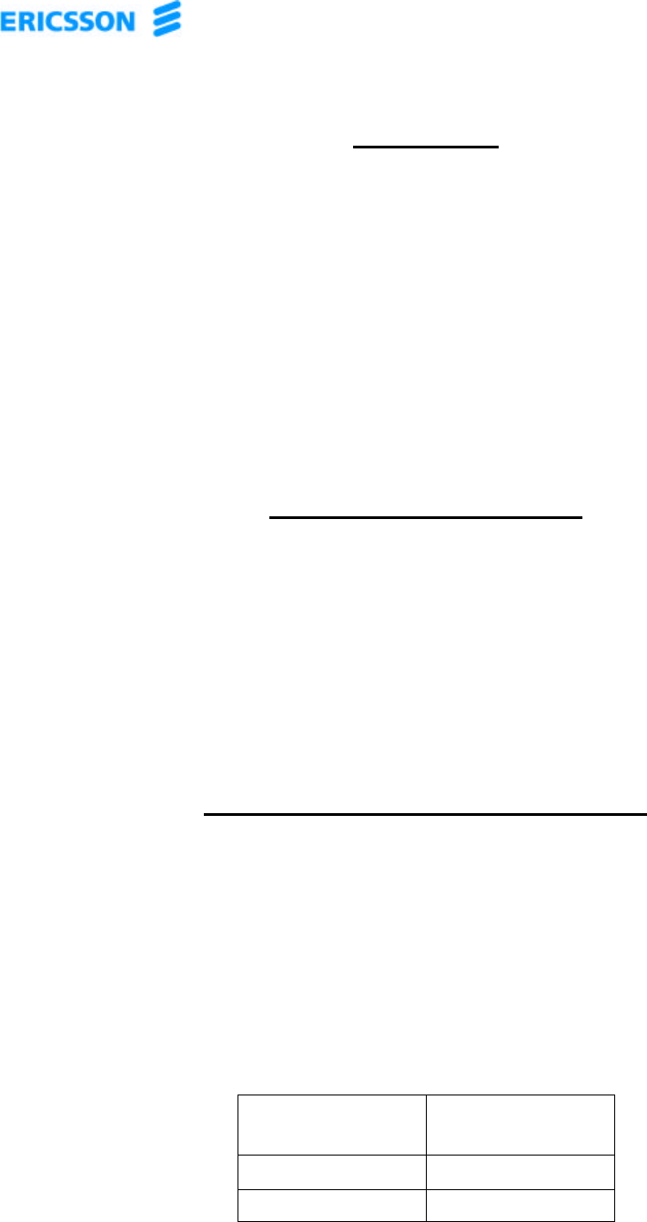
COMMENTS ON FILTER FUNCTIONS
To fulfil the cellular standard (e.g. IS-138-A) it is necessary to use a bandpass filter to
restrict spurious emissions outside the TX-band. This filter is included in the normal
base station structure.
In order to fulfil §2.1051. Spurious emission at the antenna terminal a Low Pass Filter
MUST be inserted between the subsystem output and the antenna
The filter attenuation must be greater or equal to:
Frequency
Range (Mhz) Attenuation
(dB)
910 – 1788 45
1788 - 2700 20

© 2001 – Ericsson Amplifier Technologies Inc. iii
Modifications to the subsystem, MCPA module or subrack shall not be made without
written permission from Ericsson Amplifier Technologies Inc. Unauthorized
modifications may void the authority granted under Federal Communications Rules
permitting the operation of this device.
In order not to violate the FCC certification for this device, a filter must be used
between the subsystem output and the antenna. The filter attenuation characteristics
must be greater or equal to the filter performance shown above. When the subsystem
is properly installed in its normal working environment the filter requirement is
automatically fulfilled.
© 2001 – Ericsson Amplifier Technologies Inc. iv
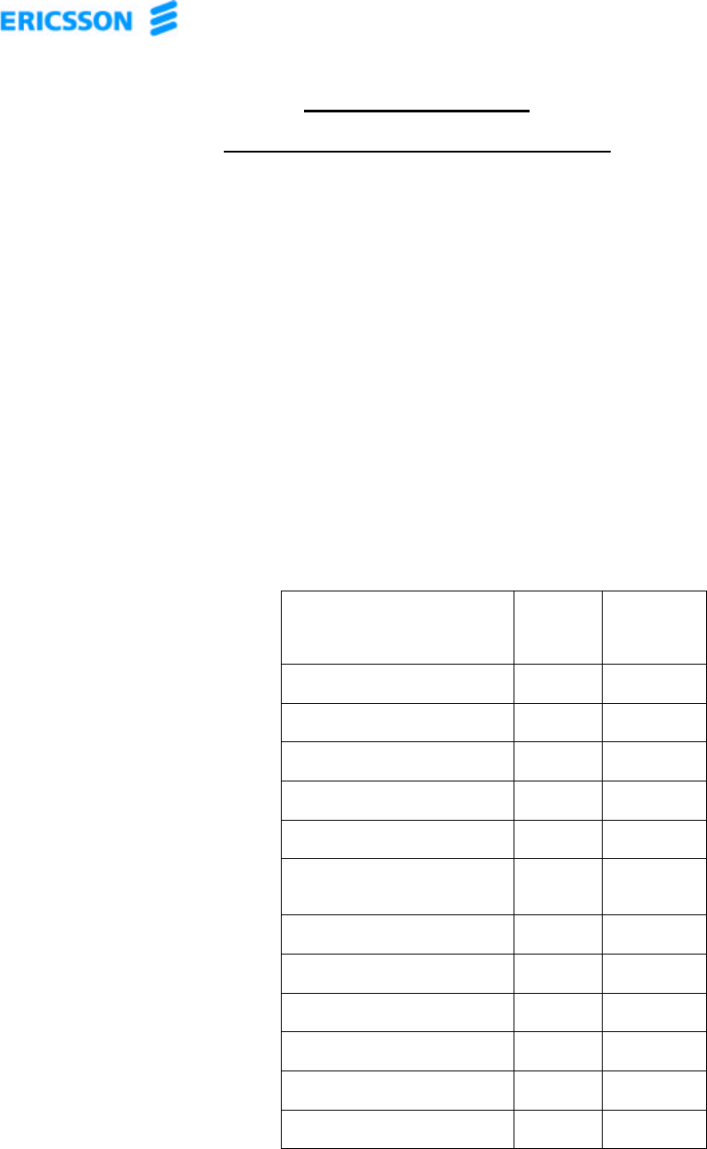
RETURN FOR REPAIR
FIELD OPERATION SUMMARY SHEET
Please make a copy of this sheet, and complete the following questionnaire. If necessary, attach
additional sheets. This information will assist in expediting repairs to the equipment, and is used for fault
trend analyses and ongoing product improvement.
FIELD TECH NAME:_______________________________ DATE: _____________________________
EQUIPMENT LOCATION (CELL SITE NUMBER): ________________________________ ___________
________________________________ ________________________________ ____________________
MODEL NUMBER: ________________________________ ________________________________ ____
SERIAL NUMBER: ________________________________ ________________________________ ____
FREQUENCY OF OPERATION: A:__________________________ B: _________________________
CARRIER POWER:________________________________ ________________________________ ____
MAXIMUM NUMBER OF CARRIERS: ________________________________ _____________________
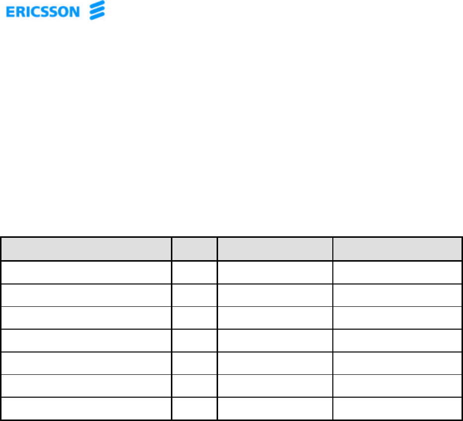
LED INDICATOR STATUS:
LED DESCRIPTION LED ON
Check þ
LED OFF
Check þ
DC ON: o o
ENABLE: o o
FAN ALARM: o o
LOOP ALARM: o o
VSWR ALARM: o o
POWER SUPPLY
ALARM:
o o
TEMPERATURE ALARM: o o
OVER POWER ALARM: o o
MINOR: o o
MAJOR: o o
CRITICAL: o o
ALC: o o

© 2001 – Ericsson Amplifier Technologies Inc. v
UNIT SURFACE TEMPERATURE: ________________________________ _______________________
POWER SUPPLY MODEL OR CAPABILITY: ________________________________ _______________
________________________________ ________________________________ ____________________
OTHER DETAILS OF PROBLEM REPORTED:________________________________ ______________
________________________________ ________________________________ ____________________
________________________________ ________________________________ ____________________
________________________________ ________________________________ ____________________

© 2001 – Ericsson Amplifier Technologies Inc. vi
Table of Contents
1. GENERAL DESCRIPTION..................................................................................... 1
1.1 Introduction ............................................................................................................................. 1
1.2 Related Publications ............................................................................................................... 1
1.3 General Description................................ ................................................................ ................. 1
1.4 Equipment Specifications.......................................................................................................3
2. INSTALLATION.....................................................................................................6
2.1 Introduction ............................................................................................................................. 6
2.2 Electrical Service Recommendations..................................................................................... 6
2.3 Receiving, Unpacking and Inspection.................................................................................... 7
2.4 Repackaging for Shipment .....................................................................................................7
2.5 Environmental Limitations......................................................................................................7
2.6 Installation ............................................................................................................................... 8
2.7 Cable Interconnections .........................................................................................................11
2.7.1 TB1 – DC Power Terminal Block.......................................................................................12
2.7.2 J4 - I/O Connector ............................................................................................................14
2.7.3 J1, J10, J17 – RF Input, RF Output and RF Sample connectors .......................................14
2.8 Verify Connections................................................................................................................ 14
2.9 Verify DC Supply Voltage...................................................................................................... 15
3. OPERATING INSTRUCTIONS.............................................................................16
3.1 Safety Precautions ................................................................................................................ 16
3.2 Controls and Indicators ........................................................................................................ 18
3.2.1 Local Controls and Indicators ............................................................................................18
3.2.2 Remote Control/Status Interface .......................................................................................19
3.3 Initial Turn On Procedure......................................................................................................19
3.4 Normal Operation.................................................................................................................. 20
3.5 Shut Down Procedure ................................................................ ........................................... 20
4. PRINCIPLES OF OPERATION............................................................................21
4.1 Introduction ........................................................................................................................... 21
4.2 RF Input Signal...................................................................................................................... 22
4.3 RF Output Load..................................................................................................................... 22
5. MAINTENANCE ...................................................................................................24
5.1 Introduction ........................................................................................................................... 24
5.2 Periodic Maintenance................................................................ ............................................ 24
5.2.1 Cleaning Air Inlets/Outlets ................................................................................................25
5.2.2 Test Equipment Required .................................................................................................25
5.2.3 Performance Tests ...........................................................................................................25
5.3 Troubleshooting Procedures................................................................................................ 26

© 2001 – Ericsson Amplifier Technologies Inc. vii
List of Appendices
Appendix A - Ericsson MCPA Module Controls and Indicators.......................................29
Appendix B - Ericsson MCPA Module Power On/Off Sequence......................................32
List of Figures
Figure 1. MCPA Subrack Assembly......................................................................................... 2
Figure 2. Recommended Circuit Breaker Configurations..................................................... 7
Figure 3. Outline and Installation Drawing,
Ericsson Amplifier Technologies MCPA Subrack Assembly............................... 10
Figure 4. Detail View, DC Power Terminal Block TB1 .......................................................... 13
Figure 5. Detail View, MCPA Local Controls and Indicators ................................................18
Figure 6. Power Saving Regions, MCPA Subrack Assembly ...............................................22
Figure 7. Block Diagram, MCPA Subrack Assembly............................................................ 24
Figure 8. Subrack Assembly Troubleshooting Flow Chart..................................................28
List of Tables
Table 1. Specifications for Ericsson MCPA Subrack Assembly ............................................3
Table 2. Nominal Gain for Installed Configuration..................................................................5
Table 3. Power Saving Operating Regions .............................................................................5
Table 4. DC Power Consumption versus Operating Status................................................... 6
Table 5. TB1 Power Terminal Block Connector....................................................................13
Table 6. I/O Connector Wiring................................................................................................ 14
Table 7. Subrack Assembly Local Controls and Indicators................................................. 18
Table 8. Nominal Gain for Amplifier Installed Configuration................................................22
Table 9. Periodic Maintenance Tasks................................ .................................................... 25
Table 10. Test Equipment Required ...................................................................................... 26

© 2001 – Ericsson Amplifier Technologies Inc. 1
1. GENERAL DESCRIPTION
1.1 Introduction
This manual provides information for the installation, operation and maintenance of
Ericsson Amplifier Technologies MCPA Subsystem. The subrack is specifically
designed for use with Ericsson Amplifier Technologies Multicarrier Power Amplifiers
(MCPAs). Refer to the separate Ericsson Amplifier Technologies Technical Manual
that accompanied the MCPA power amplifier, for specific installation, operation and
maintenance instructions for the MCPA(s). In addition, refer to the specification limits
contained in Table 1.
This manual is organized in 5 sections as follows:
• Section 1. General Description of the subrack assembly
• Section 2. Installation
• Section 3. Operating Instructions
• Section 4. Principles of Operation
• Section 5. Maintenance
1.2 Related Publications
Multicarrier Power Amplifier MCPA
Installation, Operation and Maintenance Instructions.
1.3 General Description
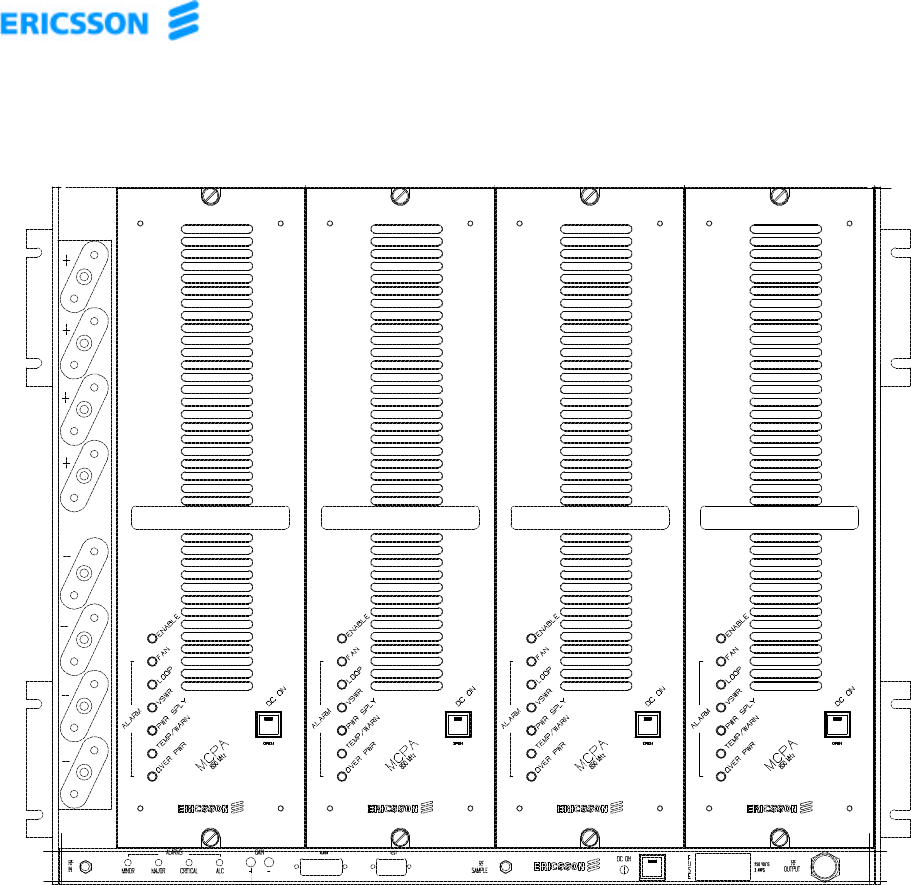
The MCPA subrack (Figure 1) is a microprocessor-controlled RF amplifier subrack
assembly that operates over the frequency range of 869 to 894 MHz. It is specifically
designed for use with up to four companion Ericsson Amplifier Technologies Multi-
Carrier Power Amplifiers (MCPAs). The subrack assembly contains an active combiner,
which automatically reconfigures itself to effectively combine the individual modules.
The active combiner uses blind mate connectors, allowing MCPA installation and
removal as needed with the subrack power on. The vertical subrack mounts in a 24-
inch rack.
User I/O is provided through the subrack assembly. The control and status of each
module is sent to the subrack assembly from the individual modules and converted into
a format suitable for the user. Local operating status is provided via front panel LED
indicators. The subrack assembly is powered by an external (customer supplied) 26-28
VDC power supply. A microprocessor board in the subrack assembly handles all the
necessary control between the individual modules, the subrack and the user. The
firmware resident in all assemblies can be updated through the subrack RS-232 port
using custom software and a laptop.
© 2001 – Ericsson Amplifier Technologies Inc. 2
Figure 1. MCPA Subsystem Assembly
(Shown with four Ericsson Amplifier Technologies MCPA’s installed)

© 2001 – Ericsson Amplifier Technologies Inc. 3
1.4 Equipment Specifications
Table 1 lists the specifications of the MCPA subsystem assembly.
Table 1. Specifications
for Ericsson MCPA Subsystem Assembly
PERFORMANCE CHARACTERISTICS
Parameter Specification
Frequency 869 – 894 MHz
Active Combined RF Output Power,
2-32 Carriers:
Normal VIN= 26-28V:
Exceptional VIN= 21-26V, 28-30V:
(1x MCPA any combination) 100 Watts Minimum
(2x MCPA any combination) 200 Watts Minimum
(3x MCPA any combination) 300 Watts Minimum
(4x MCPA any combination) 400 Watts Minimum
(1x MCPA any combination) 50 Watts Minimum
(2x MCPA any combination) 100 Watts Minimum
(3x MCPA any combination) 150 Watts Minimum
(4x MCPA any combination) 200 Watts Minimum
IMD, 869-894MHz: -63 dBc minimum
when measured with 50 random phase sets.
Spurious: -63 dBc minimum
when measured with 50 random phase sets.
Pilot Tone Level: -20 dBm with 4 MCPAs installed.
Harmonics: 2nd:40 dBc minimum
3RD and higher: 60 dBc minimum
Noise Receive Band: -35 dBm maximum / 30 kHz RBW per MCPA,
-40 dBm typical / 30 kHz RBW at 824-849 MHz
Gain Flatness: ±0.5 dB maximum (all conditions)
Gain Variation: ±0.5 dB over nominal operating range
with respect to 25ºC and 27 volt operation
Gain: 54.5 dB nominal;
Adjustable from 0 – 15 dB through front panel recessed
momentary switches.
Gain is managed in the event of a problem with an
installed MCPA, to reduce gain and permit continued
operation at reduced output. Gain is determined by
operating vs. non-operating MCPAs installed, as shown
in Table 2.

© 2001 – Ericsson Amplifier Technologies Inc. 4
Table 1. (Continued)
Specifications for Ericsson MCPA Subsystem Assembly
PERFORMANCE CHARACTERISTICS
Parameter Specification
Input VSWR: 1.5:1 maximum
Input Power: 3 dBm maximum (over full attenuator range)
Sample Port Coupling: 50 dB ±0.5 dB from main output level
Output VSWR: 2:1 Maximum
Load Stability: VSWR ∞ : 1, all phases
DC Input; Normal Conditions:
Exceptional Conditions:
26 to 28 VDC, full operation without performance
degradation; 27V @ 200.0 A typical @ 400 W (Refer to
Table 4)
21-26VDC, 28-30VDC with degraded performance.
Operating Temperature;
Normal:
Exceptional:
+5° to +40°C
5°C above and below normal limits,
with degraded performance.
Storage Temperature: -40° to +70°C
Humidity: 5% to 95% RH, non-condensing
Operating Altitude: 61 M below sea level to 3,000 M above sea level.
Vibration: 1 G/Hz from 20 to 50 Hz
Dimensions: 23” rack wide x 19” high x 18” deep
58.42 cm rack wide x 48.26 cm high x 45.72 cm deep
Subrack Main RF Input connector: J1, SMA female
Subrack Main RF Output connector: J10, N female
Subrack RF FWD Sample J17, SMA female
Subrack DC PWR Interface 8 Position Terminal Block (see Table 5)
Subrack I/O Interface 15 Pin D subminiature female connector (see Table 6);
8-bit asynchronous serial bus, which complies with the
EIA/TIA-422-A Standard for interfacing digital equipment
using differential balanced voltages.
LED Status Monitoring Low Power MCPA1 through MCPA4, and DC On
© 2001 – Ericsson Amplifier Technologies Inc. 5
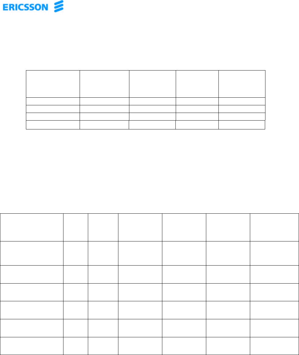
Table 2. Nominal Gain for Installed Configuration
Operational
Modules less
Non-Operational
Modules*
1 module
System 2 module
System 3 module
System 4 module
System
154.5 dB 51.5 dB 49.7 dB 48.5 dB
2-54.5 dB 52.7 dB 51.5 dB
3- - 54.5 dB 53.2 dB
4---54.5 dB
*Non-operational modules refer to modules which have been disabled due to alarms.
Above values valid during normal operation (26-28VDC input). Reduce above values by
1 dB during exceptional operating conditions (21-26VDC, 28-30VDC input).
Table 4. DC Power Consumption versus Operating Status
Ericsson MCPA Subsytem Assembly
Operating Status DC
LED
Status
Enable
LED
Status
DC Power (W)
@ 27V
1 module
DC Power (W)
@ 27V
2module
DC Power (W)
@ 27V
3 module
DC Power (W)
@ 27V
4 module
Prime Power Applied
Internal DC Status
OFF
OFF OFF 15.0 typ
17.3 max.
30.0 typ.
34.5 max.
45.0 typ.
51.8 max.
60.0 typ.
69.0 max
Bias On
(no RF)
ON ON 615.0 typ.
707.0 max.
1230.0 typ.
1415.0 max
1845.0 typ.
2122.0 max.
2460.0 typ.
2829.0 max.
Forward Power 100 W ON ON 1350.0 typ.
1553.0 max.
Forward Power 200 W ON ON 2700.0 typ.
3105.0 max.
Forward Power 300 W ON ON 4050.0 typ.
4660.0 max.
Forward Power 400 W ON ON 5400.0 typ
6210.0 max
© 2001 – Ericsson Amplifier Technologies Inc. 6
2. INSTALLATION
2.1 Introduction
This section contains receiving, unpacking and installation recommendations for the
Ericsson Amplifier Technologies MCPA subrack assembly. Carefully read and review
all of the information contained in this section before attempting to install or operate the
subrack assembly. In addition, read and review the operating instructions contained in
Section 3 before operating the equipment.
CAUTION
The subrack assembly is specifically designed for use with
Ericsson Amplifier Technologies Multicarrier Power
Amplifiers (MCPAs). Refer to the Installation, Operation and
Maintenance instructions included with the companion
MCPA before operating this equipment. Improper operation
of this equipment may cause damage to it, or to the
equipment connected to it.
2.2 Electrical Service Recommendations
It is recommended that each 400-Watt subsystem power source be equipped with one
of the circuit breaker configurations shown in Figure 2, installed in a load center with a
master mains switch or breaker. This arrangement permits service and maintenance of
the subrack assembly without the necessity for removing power to the entire site, and
ensures continuous coverage in the event that one of the two circuit breakers should
trip.
Figure 2. Recommended Circuit Breaker Configurations
75 A 75 A 75 A 75 A
150 A
300 A
150 A

© 2001 – Ericsson Amplifier Technologies Inc. 7
2.3 Receiving, Unpacking and Inspection
The subrack assembly has been tested and calibrated at the factory prior to shipment.
No additional readjustment is required prior to installation.
The subrack assembly is shipped in a single container. Check the exterior of the
shipping container for any visible signs of damage. If possible, open the container in
the presence of the delivery agent. Carefully unpack the subrack assembly and save
all packing material for possible reshipment. After removal from the container, check
the subrack assembly for physical damage such as scratched panels, damaged
connectors, etc. If damage is noted, immediately file claim with the delivery agent or
freight carrier.
2.4 Repackaging for Shipment
Should it ever become necessary to return the subrack assembly for service or repair,
the following procedure should be followed.
a. Use the original container, if possible.
b. Wrap the item in heavy paper or plastic before placing it in the shipping container.
c. Use packing material around all sides of the item.
d. Use a heavy cardboard box or a wooden container to house the item. Seal the
container with heavy-duty tape (Fiberglas) or strap the container with metal bands.
e. Mark the container: "FRAGILE - DELICATE INSTRUMENT".
2.5 Environmental Limitations
The subrack assembly is designed to operate in an environment as noted in Table 1 of
this manual. The subrack assembly must be installed in an area where an adequate
and unrestricted supply of air is available for cooling. Adequate clearance must be
provided to prevent obstruction of airflow. Confirm that proper DC power is available
for the equipment.

© 2001 – Ericsson Amplifier Technologies Inc. 8
2.6 Installation
The subrack is designed for installation into a standard 24-inch rack or enclosure.
Installation procedures vary based on site structure; however, it is recommended that
an open frame rack be used where possible. This will ensure adequate airflow for the
amplifier system. Proceed to install the subrack as follows:
WARNING
INSTALL RACK OR FRAME TO BE USED IN
ACCORDANCE WITH THE MANUFACTURER’S
INSTALLATION RECOMMENDATIONS. ENSURE THAT
THE RACK OR FRAME HAS BEEN PROPERLY AND
SECURELY FASTENED TO PREVENT IT FROM FALLING
AS THE EQUIPMENT IS INSTALLED. PERSONAL
INJURY AND EQUIPMENT DAMAGE CAN RESULT FROM
IMPROPER RACK OR FRAME INSTALLATION.
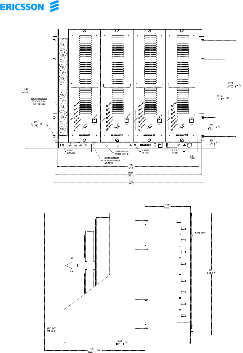
a. Refer to the Outline and Installation drawing of Figure 3, and determine where the
subrack will be positioned in the rack or frame. Four mounting brackets are located
at the sides of the assembly for securing to the rack or frame.
b. With the amplifier modules removed, lift the subrack to the desired location in the
rack or frame, aligning the eight cutouts with the screw holes of the rack.
c. Mount the subrack assembly to the rack through the eight mounting holes (two per
bracket) using eight (8) ½-inch, 10-24 threaded screws with washers. Hand tighten
hardware; do not over tighten.
d. Install the individual MCPA amplifier modules into the subrack, beginning from the
left. Use firm, but not excessive force when installing the MCPA amplifiers to
ensure a good connection is made.
e. Hand tighten the retaining screws on the front panels of the MCPAs. Do not over
tighten.
© 2001 – Ericsson Amplifier Technologies Inc. 9
Front View, Subsystem Assembly
Side View, Subsystem Assembly
Figure 3. Outline and Installation Drawing, Ericsson Amplifier Technologies MCPA
Subrack Assembly
(Shown with four Ericsson Amplifier Technologies MCPA’s Installed)
(Sheet 1 of 2)
© 2001 – Ericsson Amplifier Technologies Inc. 10
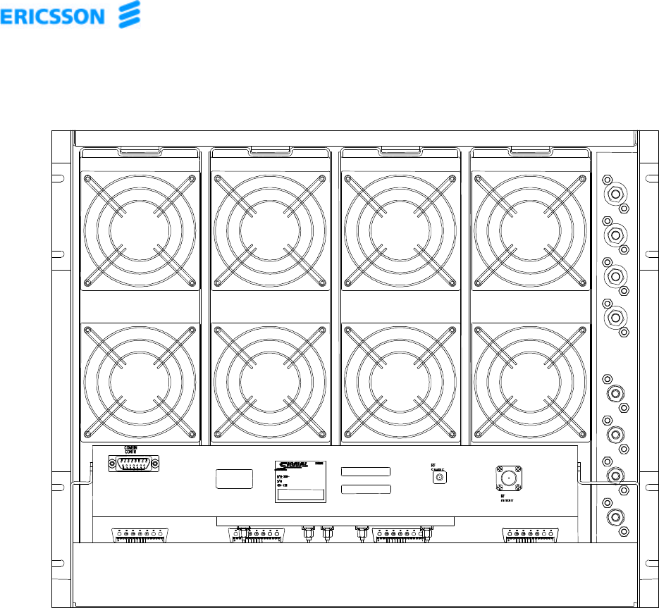
Rear View of Subsystem Assembly
Figure 3. Outline and Installation Drawing, Ericsson Amplifier Technologies MCPA
Subrack Assembly
(Shown with four Ericsson Amplifier Technologies MCPA’s Installed)
(Sheet 2 of 2)
© 2001 – Ericsson Amplifier Technologies Inc. 11
2.7 Cable Interconnections
WARNING
ENSURE THAT ALL DC AND RF POWER TO THE
SYSTEM IS DISABLED BEFORE MAKING ANY
CONNECTIONS. OPERATOR INJURY AND/OR
EQUIPMENT DAMAGE CAN RESULT FROM CARELESS
ERRORS DURING WIRING.
All DC cable interconnections are accomplished at the front of the subrack. Affix the
DC cable lugs onto the terminal block studs. Note that the positive terminal blocks
have 3/8” studs and the negative terminal blocks have ¼” studs.
NOTE
DC cables should be a minimum of 6 AWG.
Using a 9/16” wrench for the positive connections and a 7/16” wrench for the ground
connections, tighten each nut until the DC cables are securely in place. Note that the
maximum torque rating for the positive (3/8” stud) blocks are 150 lb in and 80 lb in for
the negative (1/4” stud) blocks. See Figure 4 and Table 5 for proper cable positioning
on the terminal block.
Connect the RF input to the SMA female connector located on the left of the front
plane. Using a 5/16”, open ended wrench, tighten the connection until it is snug.
Connect the RF output cable to the N female connector located to the right of the RF
input connector. Using a set of connector pliers, tighten the connection until it is snug.
Connect the 15 pin male connector to the I/O interface located on the rear of the
subrack. Using a small flat head screw driver, tighten the two retaining screws on the
sides of the I/O connector.
CAUTION
Do not connect dc power to the subrack assembly until
proper DC supply voltages have been verified. Damage
to the subrack assembly can occur if improper voltages
are applied.

© 2001 – Ericsson Amplifier Technologies Inc. 12
2.7.1 DC Power Terminal Block
The DC interface is a single column of 8 terminal blocks, as shown in the detail view of
Figure 4. TB1 through TB4 are the positive connections and TB5 through TB8 are the
ground connections.
NOTE
It is recommended that each 400-Watt Sub-system power
source be equipped with two, 125 amp circuit breakers,
installed in a load center with a master switch or breaker.
This arrangement permits service and maintenance of the
subsystem without the necessity for removing power to the
entire site, and ensures continuous coverage in the event
that one of the two circuit breakers should trip
Using the appropriate wrench, tighten each of the terminals (TB1-TB8) making sure not
to exceed the respective maximum torque rating of the blocks. Connections are as
shown in Figure 4 and Table 5.
+
+
+
+
TB1
TB2
TB3
TB4
-
-
-
-
TB5
TB6
TB7
TB8

© 2001 – Ericsson Amplifier Technologies Inc. 13
Figure 4. Detail View, DC Power Terminal Blocks TB1-TB8
Table 5. TB1-TB8 Power Terminal Block Connectors
TERMINAL DC SUPPLY CIRCUIT DESCRIPTION
TB1 125A CIRCUIT 1 + DC Power Input for
Amplifier Module 1 and
Subrack.
TB2 125A CIRCUIT 2 + DC Power Input for
Amplifier Module 2.
TB3 125A CIRCUIT 3 + DC Power Input for
Amplifier Module 3.
TB4 125A CIRCUIT 4 + DC Power Input for
Amplifier Module 4.
TB5 CIRCUIT 1 RETURN - DC Power Return for
Amplifier Module 1 and
Subrack.
TB6 CIRCUIT 2 RETURN - DC Power Return for
Amplifier Module 2.
TB7 CIRCUIT 3 RETURN - DC Power Return for
Amplifier Module 3.
TB8 CIRCUIT 4 RETURN - DC Power Return for
Amplifier Module 4.
© 2001 – Ericsson Amplifier Technologies Inc. 14
2.7.2 J4 - I/O Connector
The I/O connector is a 15 Pin D subminiature female type. The I/O Control and Status
interface is detailed in Table 6. Tighten the two retaining screws on the sides of the I/O
connector at J4, using a small flat-head screwdriver.
Table 6. I/O Connector Wiring
Pin Interface Description Subrack
I/O Electrical Protocol
1Minor (Fan Failure) OOpen = Alarm, Closed = OK
2Minor common OOpen = Alarm, Closed = OK
4Major (Single MCPA Module failure) OOpen = Alarm, Closed = OK
5Major common OOpen = Alarm, Closed = OK
6Critical (All MCPA Module Failure) OOpen = Alarm, Closed = OK
7ALC Alarm OOpen = Alarm, Closed = OK
8ALC common OOpen = Alarm, Closed = OK
9Critical common OOpen = Alarm, Closed = OK
10 Control (All modules On/Off) IOpen to Closed Edge = All modules On
Closed to Open Edge = All modules Off
Note low current 5 vdc potential is on this pin
11 Control common IGND Potential
12 Pwr On OOpen = No DC Pwr, Closed = DC Pwr on
13 Pwr On common OOpen = No DC Pwr, Closed = DC Pwr on
2.7.3 J1, J10, J17 – RF Input, RF Output and RF Sample connectors
a. Connect the system RF input cable to the subrack assembly at SMA connector J1.
Tighten the connection using a 5/16”, open ended wrench until secure.
b. Connect the system RF output cable to the subrack assembly at type N connector
J10. Tighten the connection using connector pliers until secure.
c. Connect the system RF sample output to the subrack assembly at SMA connector
J17. Tighten the connection using a 5/16”, open ended wrench until secure. This
sample port is 50 ±1 dB below the main RF output at J10.
2.8 Verify Connections
Recheck all connections. Make certain that all connections are correct and secure.
© 2001 – Ericsson Amplifier Technologies Inc. 15
2.9 Verify DC Supply Voltage
Measure the DC supply voltage that will power the subrack assembly. The voltage
must be 26 to 28 VDC (27VDC optimum). Degraded operation will result with DC input
of 21-26VDC and 28-30VDC. Never operate the system outside of these limits. Refer
to Section 3 for operating instructions.
CAUTION
DO NOT OPERATE SUBRACK ASSEMBLY WITH A DC
SUPPLY VOLTAGE OUTSIDE OF THESE LIMITS.
DAMAGE WILL OCCUR TO THE SUBRACK AND MCPAS
DUE TO APPLICATION OF IMPROPER POWER SUPPLY
VOLTAGES.
CAUTION
REFER TO THE ACCOMPANYTING TECHNICAL
MANUAL FOR THE MCPA USED WITH THE SUBRACK.
THE MCPA REQUIRES A SPECIFIC VOLTAGE. DO NOT
OPERATE MCPA AND SUBRACK ASSEMBLY WITH A DC
SUPPLY VOLTAGE OUTSIDE OF THE RANGES
SPECIFIED FOR THE MCPA. DAMAGE WILL OCCUR TO
THE MCPA DUE TO APPLICATION OF IMPROPER
POWER SUPPLY VOLTAGES.
© 2001 – Ericsson Amplifier Technologies Inc. 16
3. OPERATING INSTRUCTIONS
3.1 Safety Precautions
During normal operation, personnel must be cognizant of the intrinsic hazards related
to electronic equipment in general, and RF power amplifiers in particular. This
subsystem processes high RF power (up to 400 watts) which is dangerous and can
cause serious RF burns if contacted. Caution must be exercised when working with this
subrack assembly and related amplifier(s). While every practicable safety precaution
has been incorporated into this subrack assembly, the following rules must be strictly
observed:
WARNING
KEEP AWAY FROM LIVE CIRCUITS
Operating personnel must observe all safety regulations at
all times. Do not make adjustments inside equipment with
hazardous voltages present. Do not operate the amplifier
without proper RF termination.
DO NOT SERVICE OR ADJUST ALONE
Under no circumstances should any person reach within or
enter any enclosure for purposes of servicing or adjustment
without the immediate presence and assistance of another
person capable of rendering aid. Knowledge of first aid for
electrical shock and burns is necessary.
PERSONNEL
Only trained personnel are to service and adjust the
amplifier. Personnel must be trained in the maintenance of
equipment with hazardous RF power, and must be familiar
with this amplifier. In addition, the following precautions
must be observed during operation.
© 2001 – Ericsson Amplifier Technologies Inc. 17
WARNING
MAINTAIN PROPER TERMINATION AT THE OUTPUT
PORT OF THE SUBSYSTEM. DO NOT REMOVE OR
EXCHANGE RF CABLES OF THE OUTPUT LOAD
CIRCUIT WHILE THE SUBSYSTEM IS IN OPERATION.
DANGEROUS RF VOLTAGE MAY EXIST AT THE
FOREMOST TERMINAL OF THE INTERRUPTED LOAD
CIRCUIT DURING OPERATION.
CAUTION
All interconnecting cables must be connected prior to
application of RF power. Although the subsystem is
designed to withstand all output load conditions including
open and short circuit conditions, it is recommended to
connect an appropriate RF load to the output port of the
subsystem prior to application of RF power.
CAUTION
Maintain proper RF input to the amplifier. Damage to the
amplifier may occur if excessive RF input is applied.
© 2001 – Ericsson Amplifier Technologies Inc. 18
3.2 Controls and Indicators
The subrack assembly is equipped with a local DC ON/OFF control, and status
indicators on the front panel. A rear panel I/O interface is provided for remote status
monitoring and control. The following paragraphs detail these features.
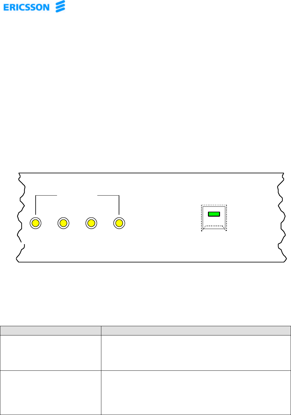
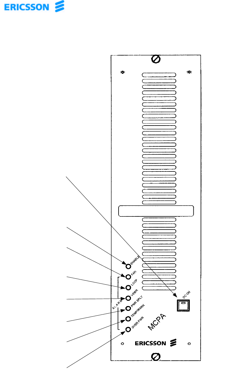
3.2.1 Local Controls and Indicators
Figure 5 is a detail view of the front panel of the subrack assembly, showing the local
controls and indicators area. Table 7 describes the controls and indicators. Refer also
to Appendix A, which contains a description of the controls and indicators provided on
the individual Ericsson MCPA amplifier modules.
Figure 5. Detail View, MCPA Subrack Local Controls and Indicators
Table 7.
Subrack Assembly Local Controls and Indicators
CONTROL/INDICATOR FUNCTION
POWER ON/OFF - Line switch (with switch cover guard) and integral
green DC ON LED indicator, enables the high power
+27V power supply circuitry.
MCPA1 through MCPA4 -Yellow LED indicating a low power output condition
from the monitored MCPA. The associated indicator is
activated when 1 or more MCPA outputs is 10 dB or
more below the others.
LOW POWER
MCPA1 MCPA2 MCPA3 MCPA4
DC ON
ALARMS
MINOR MAJOR CRITICAL ALC

© 2001 – Ericsson Amplifier Technologies Inc. 19
3.2.2 Remote Control/Status Interface
The subrack assembly is equipped with a control input as well as built-in-test (BIT)
status outputs at I/O Control and Status connector J4. The I/O Control and Status
interface is detailed in Table 6.
3.3 Initial Turn On Procedure
The following procedure is intended to verify operation of the subrack assembly
following installation, repair or replacement. Refer to the companion MCPA
Installation, Operation and Maintenance Manual for additional instructions regarding
MCPA turn on.
WARNING
EQUIPMENT OPERATORS MUST BE FAMILIAR WITH
ALL SAFETY PRECAUTIONS OUTLINED AT THE
BEGINNING OF THIS SECTION PRIOR TO OPERATING
THE SUBRACK. OPERATOR INJURY AND/OR
EQUIPMENT DAMAGE WILL RESULT FROM IMPROPER
OPERATION.
a. Verify that all connections to the subrack assembly have been properly made in
accordance with Section 2 of this manual, and the outline and installation drawing,
Figure 3.
b. With no RF applied to the subrack assembly, depress the POWER ON/OFF switch.
Depress ON/OFF switch on each MCPA module. The DC ON LED and ENABLE LED
will be illuminated.
c. Apply reduced RF input (-60 dBm) to the subrack assembly’s RF IN connector, J1
within the 869-894 MHz frequency range.
CAUTION
Maintain proper RF input level within the 869-894 MHz
operating band. Improper RF input may cause severe
subrack assembly damage.
d. Increase input level to between -15 and -11 dBm, and observe that only the DC ON
and ENABLE LEDs are illuminated.

© 2001 – Ericsson Amplifier Technologies Inc. 20
3.4 Normal Operation
The subrack assembly requires minimum attention during normal operation. Monitoring
of the BIT status outputs and RF sample output provides an overall indication of
subrack assembly health.
3.5 Shut Down Procedure
a. Reduce RF input signal level to minimum (-60 dBm).
b. Depress the ON/OFF switch to shut down the subrack assembly. Depress the
ON/OFF switch of each MCPA module to turn each off.
c. If maintenance or service is to be performed on the subrack assembly, or any of the
MCPAs, deactivate prime dc power to the subrack assembly.
WARNING
THE DC ON/OFF SWITCH DOES NOT CONTROL THE
MAIN +27 VDC FEED TO THE SUBRACK ASSEMBLY. IF
MAINTENANCE OR SERVICE IS TO BE PERFORMED ON
THE SUBRACK ASSEMBLY OR MCPAS, DEACTIVATE
PRIME DC POWER AT ITS SOURCE.

© 2001 – Ericsson Amplifier Technologies Inc. 21
4. PRINCIPLES OF OPERATION
4.1 Introduction
The subrack assembly and up to four individual Multicarrier Power Amplifier (MCPA)
modules comprise the Ericsson Amplifier Technologies MCPA subsystem. The
resulting multicarrier amplifier subsystem is capable of linearly amplifying AMPS,
TDMA and CDMA carriers at rated power. Extensive design and testing has been
accomplished to ensure proper operation with all aspects of carrier count, carrier type
and downlink power control in all of the standards. Additional standards such as EDGE
and GSM can be supported at lower power levels.
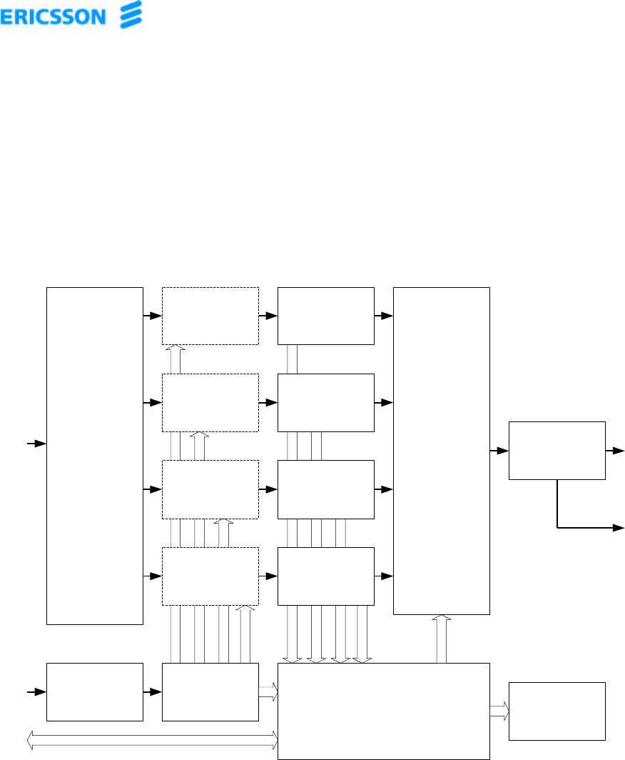
This section contains a functional description of the subrack assembly. Refer to the
block diagram of the subrack, Figure 7, located at the end of this section. The subrack
assembly contains an active combiner, which automatically reconfigures to effectively
combine the individual modules. Coupling the active combiner with blind mate
connectors allows the user to hot swap modules as needed. User I/O is provided
through the subrack assembly. The control and status of each module is sent to the
subrack assembly from the individual modules, and is converted into a format suitable
for the user. A microprocessor board in the subrack assembly handles all of the
necessary control between the individual modules, the subrack and the user. The
firmware resident in all assemblies can be updated through the subrack RS-232 port,
using custom software and a laptop.
Table 8 shows how the gain varies with installed but non-operating modules. When the
installed but non-operating module is replaced with an operational module, the
subsystem gain is restored to 54.5 dB.
Table 8.
Nominal Gain for Amplifier Installed Configuration
Operational
Amplifiers 1 module
Subsystem 2 module
Subsystem 3 module
Subsystem 4 module
Subsystem
147.5 dB 47.5 dB 47.5 dB 47.5 dB
2-50.5 dB 50.5 dB 50.5 dB
3- - 52.2 dB 52.2 dB
4---53.5 dB

© 2001 – Ericsson Amplifier Technologies Inc. 22
User connections to the subsystem include:
DC inputs for the subrack assembly
One Subrack RF input
One Subrack RF output
One Subrack RF forward output sample
One Subrack I/O interface
4.2 RF Input Signal
The maximum input signal for all carrier frequencies should not exceed the limits
specified in the electrical specifications. The input VSWR should be 2:1 maximum (or
better).
4.3 RF Output Load
The load impedance should be as close as possible to 50 ohms (VSWR of 1.5:1 or
less) over the 869-894 MHz operating frequency band to ensure maximum RF power
transfer to the load.
© 2001 – Ericsson Amplifier Technologies Inc. 23
Figure 7. Block Diagram, MCPA Subsystem Assembly
INPUT
RF POWER
DIVIDER
J1
RF INPUT
MCPA 1
MCPA 2
POWER LEVEL
SENSOR
POWER LEVEL
SENSOR
MCPA 3
MCPA 4
POWER LEVEL
SENSOR
POWER LEVEL
SENSOR
RECONFIGURABLE
OUTPUT
RF POWER
COMBINER
J2
RF OUTPUT
POWER LEVEL
SENSOR
TB1
DC INPUT
MICROPROCESSOR
DC ON/OFF SWITCH
AND INDICATOR
FUSE
J3
RF SAMPLE
J4
I/O
CONTROL
& STATUS
INTERFACE
LOW POWER
MCPA1 - MCPA4
LED
INDICATORS
© 2001 – Ericsson Amplifier Technologies Inc. 24
5. MAINTENANCE
5.1 Introduction
This section provides information for periodic maintenance of the subrack assembly, as
well as tests which are recommended in order to evaluate its performance. Refer to
paragraph 5.3 for troubleshooting procedures for the subrack assembly.
CAUTION
Do not attempt to repair the subrack assembly. The
equipment contains no user-serviceable components, with
the exception of the fuse. Further damage will result from
improper repairs.
NOTE
Do not break the seals on the equipment, as this will void
the warranty.
5.2 Periodic Maintenance
Periodic maintenance tasks and recommended intervals are listed in Table 9.
Table 9. Periodic Maintenance Tasks
CATEGORY TASK RECOMMENDED
INTERVAL MAINTENANCE ACTION
Cleaning Air
Inlets/Outlets 30 Days Inspect and clean in accordance
with paragraph 5.2.1.
Inspection Cables and
Connectors 12 Months Inspect all cables for any signs of
damage or wear. Check and
verify that all connections are
secure.
Performance
Tests 12 Months Perform tests as outlined in
paragraph 5.2.3.
© 2001 – Ericsson Amplifier Technologies Inc. 25
5.2.1 Cleaning Air Inlets/Outlets
The air inlets and outlets are located at the front and rear of the unit. Air is drawn in
from the front, and exhausted through the rear of the subrack. These areas should be
cleaned at 30 day intervals, or sooner, if the equipment is operated in a severe dust
environment. Use dry, low-pressure compressed air, or a brush with soft bristles to
loosen, remove and clean off any accumulated dust from the air inlet and outlet areas.
5.2.2 Test Equipment Required
Table 10 lists the test equipment required for evaluating the subrack performance.
Suitable equivalents may be substituted.
Table 10. Test Equipment Required
NOMENCLATURE QTY MANUFACTURER MODEL
Signal Generator 1 H/P ESG
Attenuator, 40 dB, 250 Watt 1 Weinschel S3-40-43
Attenuator, 20 dB, 20 Watt 2 Weinschel AT20
Spectrum Analyzer 1 H/P 8560E
Directional Coupler, 30 dB 1 RF Power DDC-901-931-R5-30
Power Meter/Sensor 1 H/P 437B/8481A
Power Supply 1 H/P 6673A
5.2.3 Performance Tests
Performance tests should be performed at 12-month intervals, or as directed by the
resident maintenance authority, to ensure that the subrack assembly is functioning
properly and within expected specification limits.
© 2001 – Ericsson Amplifier Technologies Inc. 26
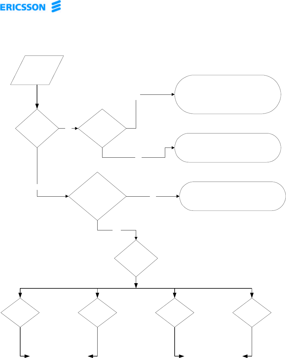
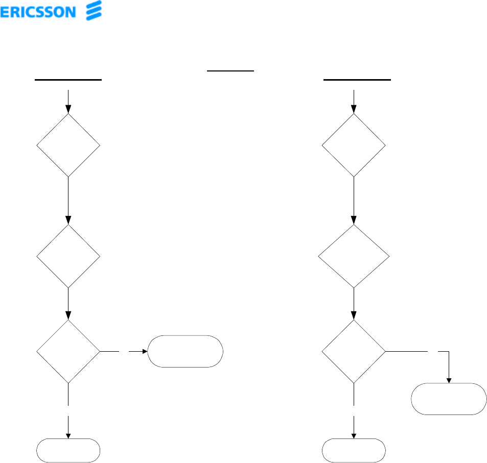
5.3 Troubleshooting Procedures
Figure 8 is the troubleshooting flow chart for the subrack assembly.
CAUTION
Do not attempt to repair the subrack assembly. The
equipment contains no user-serviceable components, with
the exception of the fuse. Further damage will result from
improper repairs.
NOTE
Do not break the seals on the equipment, as this will void
the warranty
© 2001 – Ericsson Amplifier Technologies Inc. 27
Begin Here
Is the DC ON
LED illuminated Is the fuse on the
front panel blown?
Replace fuse with another of exactly the same rating
so as to prevent further damage to equipment and to
ensurew continued protection.
Yes
No
No
Verify connections and DC power to the Surack. If
secure, return Subrack for repair.
Yes
Reset Power to the individual MCPAs. Refer to
Appendix B to reset power to each MCPA.
Are any of the LOW
POWER LEDs active? No
Follow path for
Type of Alarm.
Yes
Minor Alarm Major Alarm Critical Alarm ALC Alarm
See Sheet 2 See Sheet 3
Figure:8 Subrack Troubleshooting Flow Chart.
© 2001 – Ericsson Amplifier Technologies Inc. 28
Minor Alarm Major Alarm
Identify and
Reset Faultly
MCPA
Identify and
Reset Faultly
MCPA(s) Reset
Subrack
Alarm Cleared
Return to Service
No
Yes
Alarm Cleared
Return to Service
Yes
No
SHEET. 2
From Sheet 1 From Sheet 1
Replace MCPA and
return for repair.
Replace MCPA and
return for repair.
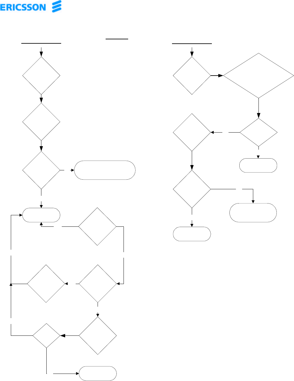
© 2001 – Ericsson Amplifier Technologies Inc. 29
Critical Alarm
Identify and
Reset Faultly
MCPAs Reset
Subrack
Alarm Cleared
Return to Service
ALC Alarm
Identify and
Reset Faultly
MCPAs
Return to Service
Alarm Cleared No
Yes
No
Alarm Cleared
No
Yes
Verify Drive
level to subrack
& VSWR
Alarm Cleared Yes
Yes
Adjust Drive
level or correct
VSWR.
Alarm
Cleared
Yes
Return Subrack for
repair
No
Sheet 3
From Sheet 1 From Sheet 1
Replace MCPA(s) and
return for repair
If MCPAs show
Over Pwr alarm,
check & adjust subrack drive
level
Alarm cleared
Return to service
Yes
No
Yes
No
Replace MCPA(s) and return
for repair.

© 2001 – Ericsson Amplifier Technologies Inc. 30
APPENDIX A
Ericsson MCPA Module
Controls and Indicators
© 2001 – Ericsson Amplifier Technologies Inc. 31
MCPA Local Controls and Indicators
ENABLE LED
FAN LED
LOOP LED
VSWR LED
PWR SPLY LED
OVER PWR LED
DC ON/OFF SWITCH
AND INDICATOR
TEMP/WARN LED
ENABLE
SWITCH
© 2001 – Ericsson Amplifier Technologies Inc. 32
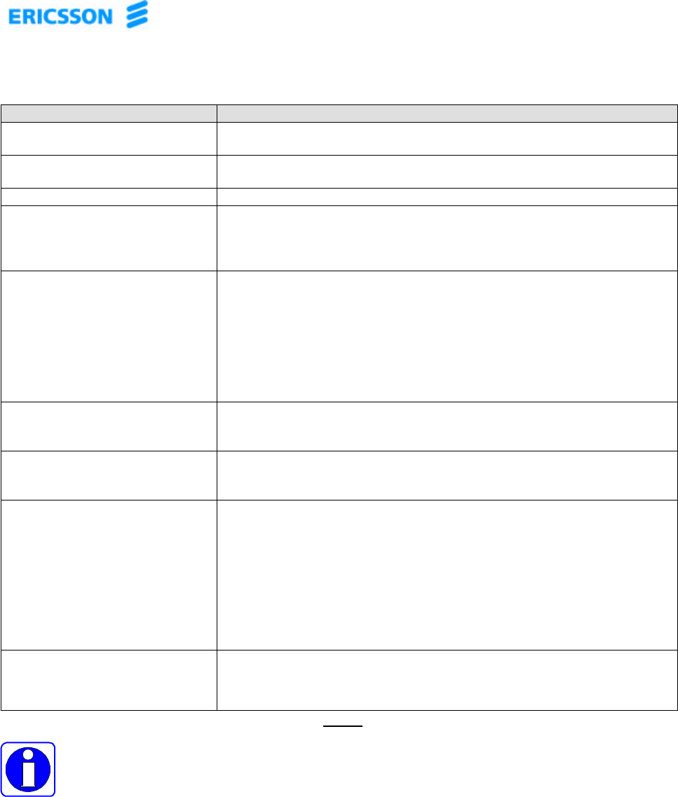
MCPA Local Controls and Indicators
CONTROL/INDICATOR FUNCTION
DC ON - Power Supply switch and integral DC ON green LED indicator, enables
the external high power +27V power supply circuitry.
ENABLE ON - Green LED indicates unit is ENABLED, biased on and the amplifier is
ready to amplify signals.
FAN ALARM - Yellow LED indicating a blocked or non-functioning fan.
LOOP ALARM
(Steady On)- Steady (not blinking) Red LED indicating internal control loops can no
longer minimize IMD performance. The sequence of disable and
enable commands may be used to reset the loops to their normal
conditions.
LOOP ALARM –
(Blinking On/Off, indicates
Locking Mode)
Blinking red LED indicating Locking Mode has been entered. The
locking mode is used to indicate when the module is unable to
minimize IMD performance and is attempting to adjust loop
coefficients. During this mode, IMD performance may not meet
specified values. The module will attempt to improve performance for
1 minute. If unable to improve performance during this period, the
module will indicate a loop alarm and enter the shutdown mode, and
will require power to be reset in order to clear the fault.
VSWR ALARM - Red LED indicating load VSWR is greater than 3.0:1. Amplifier will
enter shutdown mode, and will require power to be reset in order to
clear the fault.
POWER SUPPLY ALARM - Red LED indicating a power supply generated voltage is out of range.
Amplifier will enter shutdown mode, and will require power to be reset
in order to clear the fault.
TEMP WARNING/ALARM -
Dual color (Yellow/Red) LED. TEMP WARNING: Yellow color indicates approach of excessive
operating temperature of approximately +80°C as monitored on the
heatsink. Operation of the MCPA can continue uninterrupted during
this warning condition.
TEMP ALARM: Red color indicates excessive operating temperature
of approximately +90°C as monitored on the heatsink. Operation of
the MCPA is disabled until the heatsink has cooled to a safe operating
temperature, at which point, operation will automatically resume.
OVERPOWER ALARM - Red LED indicating that the RF output power from the MCPA is greater
than 2 dB above nominal output power. Amplifier will enter shutdown
mode, and will require power to be reset in order to clear the fault.
NOTE
Activation of the LOOP ALARM, VSWR ALARM, POWER SUPPLY
ALARM, TEMP ALARM or OVERPOWER ALARM will cause the
Amplifier to enter shutdown mode. The amplifier will attempt to auto
recover up to three times within 24 hours. If the alarm is still present, the
amplifier will continue to shutdown. The amplifier may also be manually
reset using the front panel button. Refer to Figure 4, which details the
ON/OFF sequence of the MCPA.

© 2001 – Ericsson Amplifier Technologies Inc. 33
APPENDIX B
Ericsson MCPA Module
Power On/Off Sequence
© 2001 – Ericsson Amplifier Technologies Inc. 34
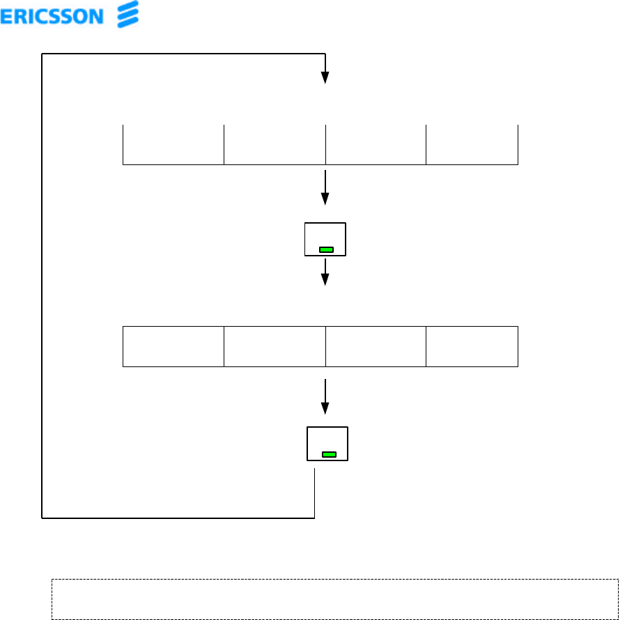
Power Amplifier Module Power ON/OFF Sequence
Initial state.
MCPA is shut down.
Minimal current draw.
Module bias is
applied. MCPA is
enabled as indicated
by front panel
ENABLE LED.
Current draw
approximately 18
amps.
OFF OFF OFF DISABLED
DC ON LED
STATUS ENABLE LED
STATUS
INTERNAL
POWER SUPPLY
STATUS
MCPA
STATUS
DC ON/OFF
DEPRESS
ON ON ON ENABLED
DC ON LED
STATUS ENABLE LED
STATUS
INTERNAL
POWER SUPPLY
STATUS
MCPA
STATUS
DC ON/OFF
DEPRESS
OPERATING
STATUS
OPERATING
STATUS
NOTE:
If resetting power to the MCPA does not clear the fault condition, contact Ericsson Amplifier Technologies,
or return MCPA for service.