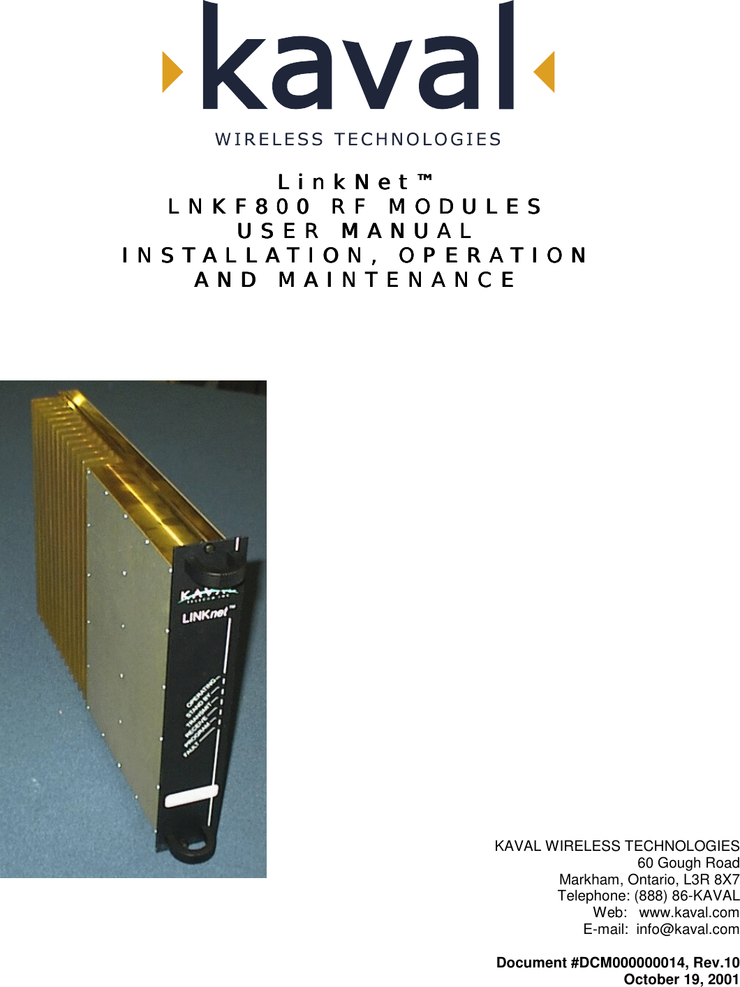
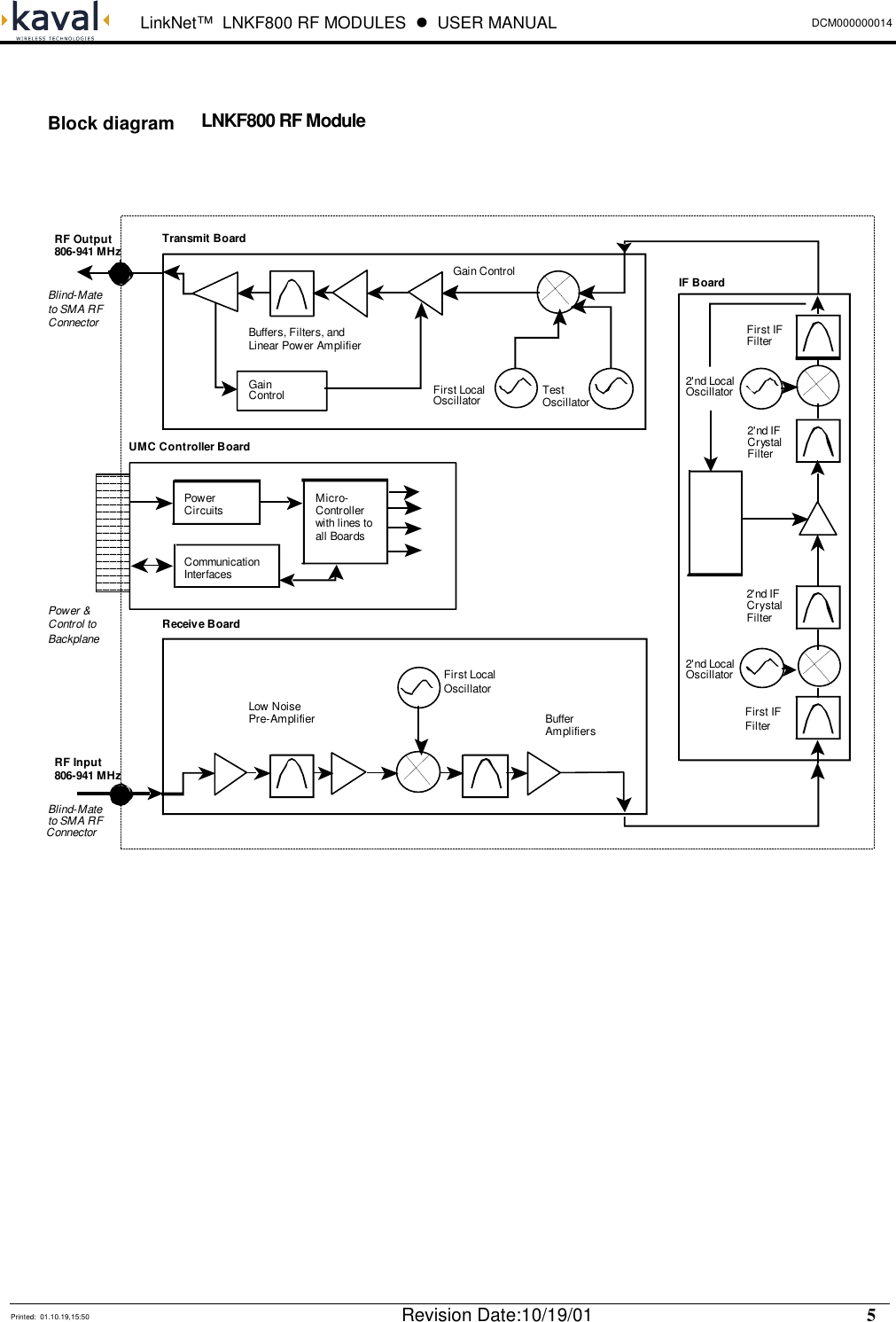
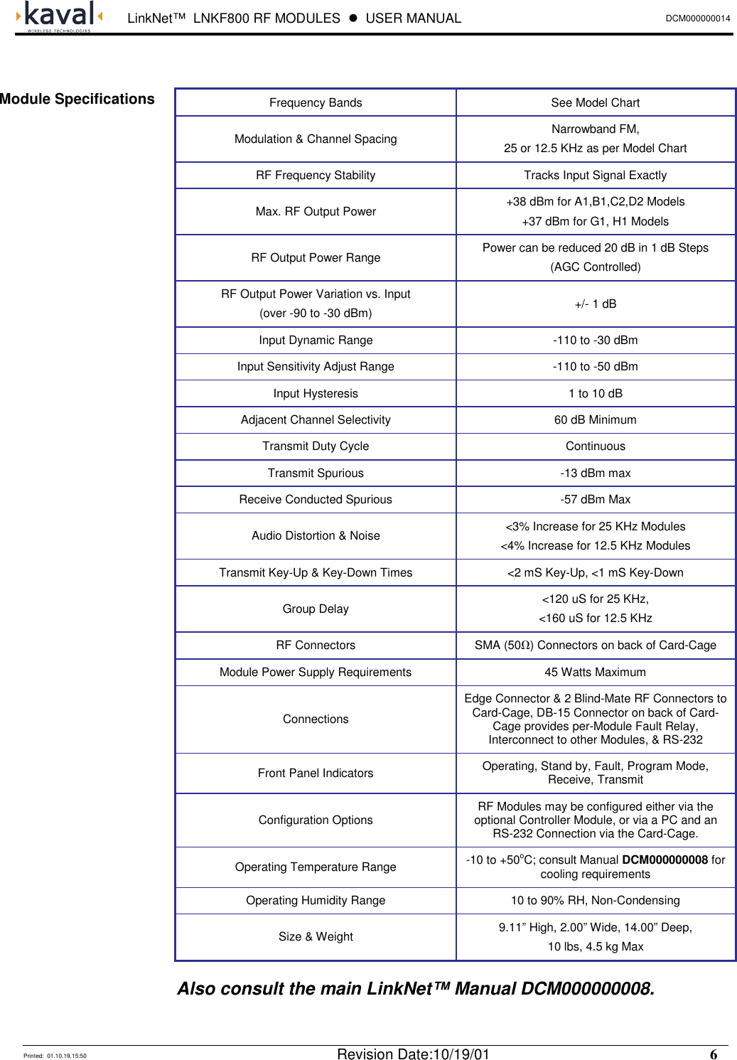
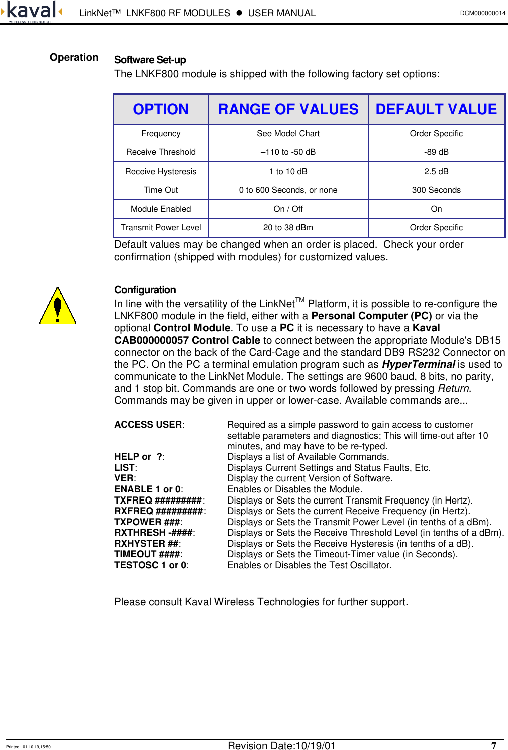
Powerwave Technologies LNKF800 LinkNet LNKF800 Repeater Module User Manual

Powerwave Technologies Inc. LinkNet LNKF800 Repeater Module Users Manual

Users Manual

  LinkNet™LinkNet™LinkNet™LinkNet™ LNKF800 RF MODULESLNKF800 RF MODULESLNKF800 RF MODULESLNKF800 RF MODULES    USER MANUALUSER MANUALUSER MANUALUSER MANUAL    INSTALLATION, OPERATIONINSTALLATION, OPERATIONINSTALLATION, OPERATIONINSTALLATION, OPERATION    AND MAINTENANCEAND MAINTENANCEAND MAINTENANCEAND MAINTENANCE       KAVAL WIRELESS TECHNOLOGIES 60 Gough Road Markham, Ontario, L3R 8X7 Telephone: (888) 86-KAVAL Web:   www.kaval.com E-mail:  info@kaval.com  Document #DCM000000014, Rev.10 October 19, 2001
 LinkNet™  LNKF800 RF MODULES  !  USER MANUAL DCM000000014   Printed:  2001-10-19 15:50:25  Revision Date: 10/19/01:  ii  PPPPPPPPRRRRRRRROOOOOOOOPPPPPPPPRRRRRRRRIIIIIIIIEEEEEEEETTTTTTTTAAAAAAAARRRRRRRRYYYYYYYY        SSSSSSSSTTTTTTTTAAAAAAAATTTTTTTTEEEEEEEEMMMMMMMMEEEEEEEENNNNNNNNTTTTTTTT         © 2000 KAVAL WIRELESS TECHNOLOGIES All rights reserved. No part of this publication, or any software included with it may be reproduced, stored in a retrieval system, or transmitted in any form or by any means, including photocopying, electronic, mechanical, recording or otherwise, without the prior written permission of the copyright holder. This document contains proprietary information of KAVAL WIRELESS TECHNOLOGIES The contents are confidential and any disclosure to persons other than the officers, employees, agents or subcontractors of the owner or licensee of this document, without the prior written consent of KAVAL WIRELESS TECHNOLOGIES, is strictly prohibited.  KAVAL WIRELESS TECHNOLOGIES provides this document as is, without any warranty of any kind either expressed or implied including, but not limited to, the implied warranties of merchantability and fitness of a particular purpose. KAVAL WIRELESS TECHNOLOGIES may make changes or improvements in the equipment, software, or specifications described in this document at any time and without notice. These changes will be incorporated in new releases of this document.  This document may contain technical inaccuracies or typographical errors. KAVAL WIRELESS TECHNOLOGIES waives responsibility for any labour, materials, or costs incurred by any person or party as a result of using this document. KAVAL WIRELESS TECHNOLOGIES, and any of its affiliates shall not be liable for any damages (including, but not limited to, consequential, indirect or incidental, special damages or loss of profits or date) even if they were foreseeable and KAVAL WIRELESS TECHNOLOGIES has been informed of their potential occurrence, arising out of or in connection with this document or its use.   TTTTTTTTRRRRRRRRAAAAAAAADDDDDDDDEEEEEEEE        MMMMMMMMAAAAAAAARRRRRRRRKKKKKKKK        NNNNNNNNOOOOOOOOTTTTTTTTIIIIIIIICCCCCCCCEEEEEEEE        This manual makes reference to trademarks that are the property of other companies.  References are used only to refer to the products or services of the trademark owners.  LinkNet™ is a trademark of KAVAL WIRELESS TECHNOLOGIES
 LinkNet™  LNKF800 RF MODULES  !  USER MANUAL DCM000000014   Printed:  2001-10-19 15:50:25  Revision Date: 10/19/01:  iii  TABLE OF TABLE OF TABLE OF TABLE OF CONTENTSCONTENTSCONTENTSCONTENTS    1. LNKF800 MODULES ................................ 4 OVERVIEW.............................................................. 4 Theory Of Operation ......................................... 4 MODELS................................................................. 4 BLOCK DIAGRAM..................................................... 5 LNKF800 RF Module ........................................ 5 MODULE SPECIFICATIONS....................................... 6 OPERATION............................................................ 7 Software Set-up ................................................ 7 Configuration..................................................... 7 Power On Self Test (POST).............................. 8 Normal Operation.............................................. 9 LINKNET FM MODULE Module .....................10 ANTENNA INSTALLATION........................................11
 LinkNet™  LNKF800 RF MODULES  !  USER MANUAL DCM000000014   Printed:  01.10.19,15:50  Revision Date:10/19/01    4    Theory Of Operation An LINKNET FM MODULE is a radio repeater that simultaneously receives and transmits a single narrow band radio channel on exactly the same frequency.  The LINKNET FM MODULE accomplishes its repeater function without store and forward circuitry, or expensive conventional simulcasting techniques. The fact that the same frequency is retransmitted by an LINKNET FM MODULE means that additional frequency allocations are not required in situations where an existing radio coverage pattern needs to be extended. The most common LINKNET FM MODULE applications are the extension of above ground signals into buildings, tunnels, vehicles or the extension of radio coverage patterns into outdoor shaded areas such as deep valleys. From an applications standpoint, an LINKNET FM MODULE is very similar to a regular two-way radio repeater. LINKNET FM MODULES can be combined using regular two-way radio multicoupling or duplexing equipment and have input and output signal characteristics to those of regular transmitters and receivers. The one special consideration in LINKNET FM MODULE systems is that of input to output antenna isolation. This must be carefully engineered for each installation. LINKNET FM MODULES are designed for indoor use only and are intended for mounting in a standard EIA 19 inch rack. The Modular design of LINKNET FM MODULE circuitry allows for easy servicing, stocking of spares, adaptability and upgrade ability. LNKF800 MODULE FAMILY MODEL  TYPE  FREQUENCY LNKF800-A1  25 KHz FM Channels  806-824 MHz (FM) LNKF800-B1  25 KHz FM Channels  851-869 MHz (FM) LNKF800-C2  12.5 KHz FM Channels  806-824 MHz (FM) LNKF800-D2  12.5 KHz FM Channels  851-869 MHz (FM) LNKF800-G1  12.5 KHz FM Channels  896-902 MHz (FM) LNKF800-H1  12.5 KHz FM Channels  935-941 MHz (FM)  1. LNKF800 MODULESOverview Models
 LinkNet™  LNKF800 RF MODULES  !  USER MANUAL DCM000000014   Printed:  01.10.19,15:50  Revision Date:10/19/01    5    LNKF800 RF Module  Block diagram Transmit BoardUMC Controller BoardReceive BoardIF BoardRF Input806-941 MHzRF Output806-941 MHzMicro-Controllerwith lines toall BoardsBlind-Mateto SMA RFConnectorBlind-Mateto SMA RFConnectorPower &Control toBackplaneGain ControlCommunicationInterfacesGainControl TestOscillatorLow NoisePre-Amplifier BufferAmplifiers2'nd LocalOscillatorFirst LocalOscillatorBuffers, Filters, andLinear Power AmplifierPowerCircuitsFirst LocalOscillator2'nd IFCrystalFilterFirst IFFilterFirst IFFilter2'nd IFCrystalFilter2'nd LocalOscillator
 LinkNet™  LNKF800 RF MODULES  !  USER MANUAL DCM000000014   Printed:  01.10.19,15:50  Revision Date:10/19/01    6    Frequency Bands  See Model Chart Modulation & Channel Spacing  Narrowband FM, 25 or 12.5 KHz as per Model Chart RF Frequency Stability  Tracks Input Signal Exactly Max. RF Output Power  +38 dBm for A1,B1,C2,D2 Models +37 dBm for G1, H1 Models RF Output Power Range  Power can be reduced 20 dB in 1 dB Steps (AGC Controlled) RF Output Power Variation vs. Input (over -90 to -30 dBm)  +/- 1 dB Input Dynamic Range  -110 to -30 dBm Input Sensitivity Adjust Range  -110 to -50 dBm Input Hysteresis  1 to 10 dB Adjacent Channel Selectivity  60 dB Minimum Transmit Duty Cycle  Continuous Transmit Spurious  -13 dBm max Receive Conducted Spurious  -57 dBm Max Audio Distortion & Noise  <3% Increase for 25 KHz Modules <4% Increase for 12.5 KHz Modules Transmit Key-Up & Key-Down Times  <2 mS Key-Up, <1 mS Key-Down Group Delay  <120 uS for 25 KHz, <160 uS for 12.5 KHz RF Connectors  SMA (50Ω) Connectors on back of Card-Cage Module Power Supply Requirements  45 Watts Maximum Connections Edge Connector & 2 Blind-Mate RF Connectors to Card-Cage, DB-15 Connector on back of Card-Cage provides per-Module Fault Relay, Interconnect to other Modules, & RS-232 Front Panel Indicators  Operating, Stand by, Fault, Program Mode, Receive, Transmit Configuration Options  RF Modules may be configured either via the optional Controller Module, or via a PC and an RS-232 Connection via the Card-Cage. Operating Temperature Range  -10 to +50oC; consult Manual DCM000000008 for cooling requirements Operating Humidity Range  10 to 90% RH, Non-Condensing Size & Weight  9.11” High, 2.00” Wide, 14.00” Deep, 10 lbs, 4.5 kg Max  Also consult the main LinkNet™ Manual DCM000000008.Module Specifications
 LinkNet™  LNKF800 RF MODULES  !  USER MANUAL DCM000000014   Printed:  01.10.19,15:50  Revision Date:10/19/01    7    Software Set-up The LNKF800 module is shipped with the following factory set options: OPTION  RANGE OF VALUES  DEFAULT VALUE Frequency  See Model Chart  Order Specific Receive Threshold –110 to -50 dB  -89 dB Receive Hysteresis  1 to 10 dB  2.5 dB Time Out  0 to 600 Seconds, or none  300 Seconds Module Enabled  On / Off  On Transmit Power Level  20 to 38 dBm  Order Specific Default values may be changed when an order is placed.  Check your order confirmation (shipped with modules) for customized values.   Configuration In line with the versatility of the LinkNetTM Platform, it is possible to re-configure the LNKF800 module in the field, either with a Personal Computer (PC) or via the optional Control Module. To use a PC it is necessary to have a Kaval CAB000000057 Control Cable to connect between the appropriate Module's DB15 connector on the back of the Card-Cage and the standard DB9 RS232 Connector on the PC. On the PC a terminal emulation program such as HyperTerminal is used to communicate to the LinkNet Module. The settings are 9600 baud, 8 bits, no parity, and 1 stop bit. Commands are one or two words followed by pressing Return. Commands may be given in upper or lower-case. Available commands are... ACCESS USER:  Required as a simple password to gain access to customer settable parameters and diagnostics; This will time-out after 10 minutes, and may have to be re-typed. HELP or  ?:  Displays a list of Available Commands. LIST:  Displays Current Settings and Status Faults, Etc. VER:  Display the current Version of Software. ENABLE 1 or 0:  Enables or Disables the Module. TXFREQ #########:  Displays or Sets the current Transmit Frequency (in Hertz). RXFREQ #########:  Displays or Sets the current Receive Frequency (in Hertz). TXPOWER ###:  Displays or Sets the Transmit Power Level (in tenths of a dBm). RXTHRESH -####:  Displays or Sets the Receive Threshold Level (in tenths of a dBm). RXHYSTER ##:  Displays or Sets the Receive Hysteresis (in tenths of a dB). TIMEOUT ####:  Displays or Sets the Timeout-Timer value (in Seconds). TESTOSC 1 or 0:  Enables or Disables the Test Oscillator.  Please consult Kaval Wireless Technologies for further support.Operation
 LinkNet™  LNKF800 RF MODULES  !  USER MANUAL DCM000000014   Printed:  01.10.19,15:50  Revision Date:10/19/01    8     Power On Self Test (POST) Each system module automatically performs a self-diagnostics when inserted into the system Card-cage.  These tests determine that the unit is a) correctly installed in the Card-cage and b) not damaged in transit.  • All six of the LED’s on the front panel will flash 3 times •  If the LED’s do NOT flash three times, then remove the module, check the power source, and re-insert the module, (See Installation Instructions). • If the card is “OK” the LED’s will continue normally. (See Normal Operation) • If there is a fault, then the Red Fault LED will remain on.  If this occurs, contact your KAVAL WIRELESS TECHNOLOGIES Service Representative, (See Warranty / RMA Procedures).  The Power On Self Test is Not an RF test, it only verifies that there is power to the unit and that the logical circuitry is functioning.
 LinkNet™  LNKF800 RF MODULES  !  USER MANUAL DCM000000014   Printed:  01.10.19,15:50  Revision Date:10/19/01    9   Normal Operation  The LNKF800 Module has six LED’s on the faceplate: 1.  OPERATING - Under normal operating conditions, this LED will flash GREEN when RF Data is present. 2.  STANDBY – Under the control of the Controller Module, the LNKF800 Module has the ability to act as a duplex transmitter, sitting perpetually in Stand by Mode waiting for the primary transmitter to fail. This LED should be constant Amber. If a Fault should occur with the primary module, the “Stand by” unit will immediately become the primary unit, at which time the Stand by LED will be turned off and the LED’s will show an operating Module. 3.  TRANSMIT – This Green LED will be on when a signal is being transmitted 4.  RECEIVE – This Green LED will be on when a signal is being received 5.  PROGRAM – This LED will be constant Amber when the unit is being re-programmed by the Controller Module. This will signify that the unit is powered on but unavailable for use. 6.  FAULT – Red LED, If the internal diagnostics for the module detect a problem, then this LED will remain on
 LinkNet™  LNKF800 RF MODULES  !  USER MANUAL DCM000000014   Printed:  01.10.19,15:50  Revision Date:10/19/01   10    LINKNET FM MODULE Module
 LinkNet™  LNKF800 RF MODULES  !  USER MANUAL DCM000000014   Printed:  01.10.19,15:50  Revision Date:10/19/01   11    •   All Antenna Installation to be performed by Qualified Technical Personnel only. •   Antenna Installation Instructions and locations below are for the purpose of satisfying FCC RF Exposure Compliance requirements. •  Note that if multiple LinkNet™ Modules are used, the Instructions below apply to the composite power output of all Modules when transmitting simultaneously. •  The Roof Top Antenna or Antennae for linking to the Donor Site(s) is/are directional (high gain) Antennae, fixed-mounted physically on the side or top of a building, or on a tower. The Antenna Gain must be no more than 10 dB. If multiple LinkNet™ Modules are used with output combiners into any one Antenna, and/or multiple Antennae are used on one Roof Top, then the sum of composite powers into all Roof Top Antennae must not exceed 100 Watts maximum. Please consult Kaval Wireless for assistance as required. The Roof Top Antennae location should be such that only Qualified Technical Personnel can access it, and that under normal operating conditions no other person can touch the Antenna, or approach within 10 meters of the Antenna. •  The In-Building Antenna connection is via a coaxial cable distribution system with Signal Taps at various points connected to the fixed-mounted Indoor Antennae. This is shown in the figure in the Introduction. The Indoor Antennae are simple 1/4 Wavelength (0 dB Gain) types. They are used with KAVAL WIRELESS TECHNOLOGIES 12, 16, or 20 dB Cable Taps. As such the maximum EIRP will be at the first Tapped Antenna, which will be 12 dB below the maximum signal level of the LinkNet™ (+40 dBm); +28 dBm, or 0.63 Watts EIRP. If multiple LinkNet™ Modules are used with output combiners, then the composite power output of all Modules transmitting simultaneously must meet this maximum EIRP requirement. Please consult Kaval Wireless for assistance as required. These Antennae are to be installed such that no person can touch the Antenna, or approach within 0.2 Meters.   ANTENNA INSTALLATION WARNING  ALL ANTENNA INSTALLATION IS TO BE PERFORMED BY QUALIFIED TECHNICAL PERSONNEL ONLY.  ANTENNA INSTALLATION INSTRUCTIONS AND LOCATIONS ARE FOR THE PURPOSE OF SATISFYING FCC RF EXPOSURE COMPLIANCE REQUIREMENTS, AND ARE NOT OPTIONAL.  ALL ROOF TOP ANTENNA INSTALLATION MUST BE SUCH THAT NO PERSON CAN TOUCH THE ANTENNA, OR APPROACH CLOSER THAN 10 METERS.   ALL IN-BUILDING ANTENNAE INSTALLATIONS MUST BE SUCH THAT NO PERSON CAN TOUCH THE ANTENNAE, OR APPROACH CLOSER THAN 0.2 METERS.   Antenna Installation

Navigation menu