Powerwave Technologies S21008 Masthead amplifier enhances performance of PCS, PC User Manual Installation and Operating Manual
Powerwave Technologies, Inc. Masthead amplifier enhances performance of PCS, PC Installation and Operating Manual
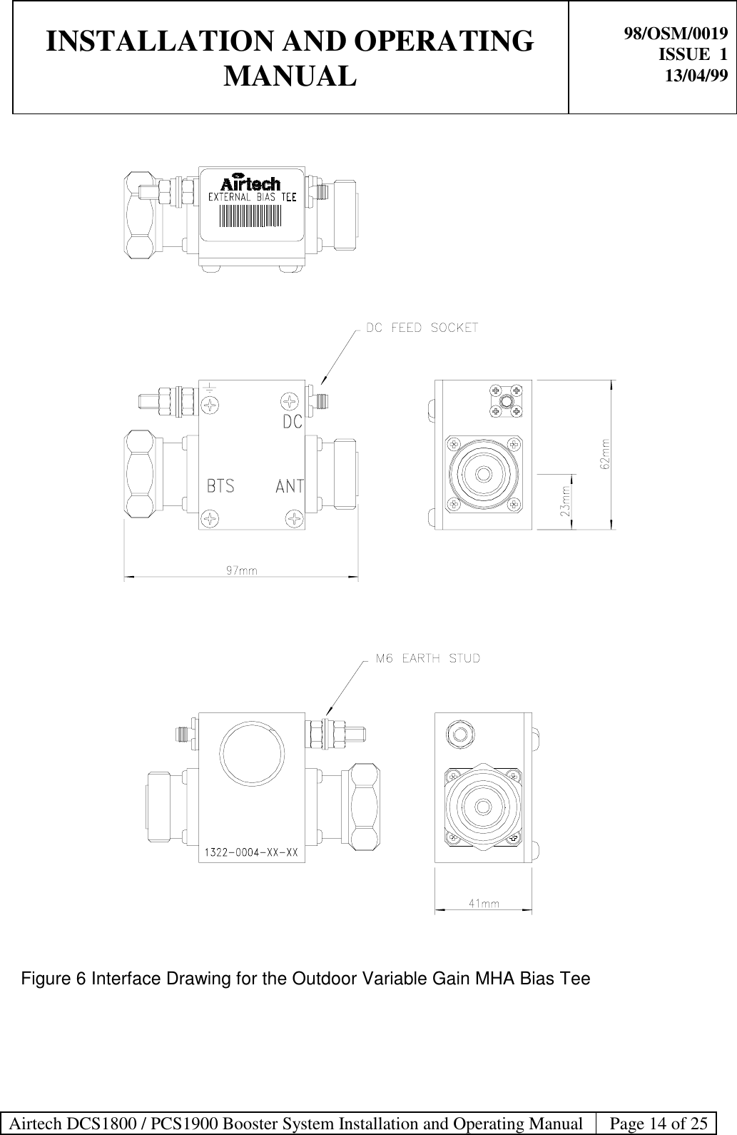
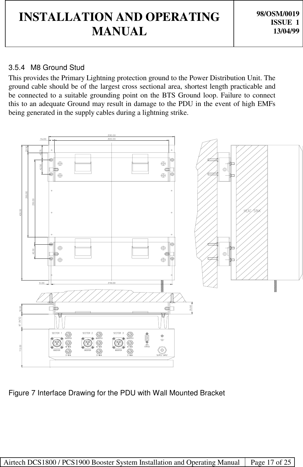
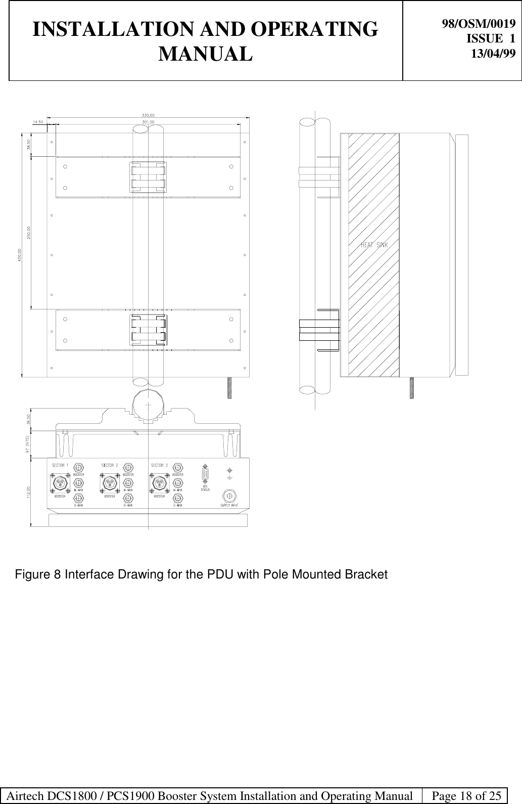
Installation and Operating Manual